Pego ECP 200 EXPERT Use And Maintenance Manual
Hide thumbs
Also See for ECP 200 EXPERT:
- Use and maintenance manual (32 pages) ,
- User and maintenance manual (28 pages) ,
- Use manual (17 pages)
Advertisement
Quick Links
Advertisement

Related Manuals for Pego ECP 200 EXPERT


Summary of Contents for Pego ECP 200 EXPERT
- Page 1 ECP 200 EXPERT USE AND MAINTENANCE MANUAL REV. 04-06...
- Page 2 ECP200 EXPERT...
-
Page 3: Table Of Contents
ECP200 EXPERT CONTENTS INTRODUCTION CHAP. 1 Page 4 General Page 4 Product ID codes Page 5 Overall dimensions Page 5 Identification data INSTALLATION CHAP. 2 Page 6 Important information for the installer Page 6 Standard assembly kit Page 7 Installing the unit FUNCTIONS CHAP. -
Page 4: General
CHAP. 1 - Introduction ECP200 EXPERT CHAPTER 1: INTRODUCTION GENERAL DESCRIPTION: The ECP200 EXPERT is a new control panel for cold rooms with a single-phase compressor up to 2 HP, specially designed to provide the user with safety, protection, control and ease of installation. It allows the user to control all the components on a refrigerating system: compressor, evaporator fans, defrosting elements, room light and thermostat-holder demisting element. - Page 5 CHAP. 1 - Introduction ECP200 EXPERT OVERALL DIMENSIONS Dimensions (mm.) IDENTIFICATION DATA The unit described in this manual has an ID plate on the side showing all the relevant identification data: • Name of Manufacturer • Code and model of unit electrical board •...
-
Page 6: Important Information For The Installer
CHAP. 2 - Installation ECP200 EXPERT CHAPTER 2: INSTALLATION IMPORTANT INFORMATION FOR THE INSTALLER 1. Install the device in places where the protection rating is observed and try not to damage the box when drilling holes for wire/pipe seats. 2. Do not use multi-polar cables in which there are wires connected to inductive/power loads or signalling wires (e.g. - Page 7 CHAP. 2 - Installation ECP200 EXPERT INSTALLING THE UNIT Fig. 1: Raise the transparent cover that shields the magneto-thermal cut-out switch and remove the screw cover on the right-hand side. Fig. 2: Undo the 4 fixing screws at the front of the box. Fig.
- Page 8 CHAP. 2 - Installation ECP200 EXPERT Fig. 6: Use the three existing holes to fix the box back panel to the wall: use three screws of a length suitable for the thickness of the wall to which the panel will be attached. Fit a rubber washer (supplied) between...
-
Page 9: Ecp200 Expert Panel Functions
CHAP. 3 - Functions ECP200 EXPERT CHAPTER 3: FUNCTIONS ECP200 EXPERT PANEL FUNCTIONS Display and adjustment of cold room temperature accurate to 0.1 °C. Display of evaporator temperature from parameter System control activation/deactivation System warnings (probe/sensor errors, minimum and maximum temperature warnings, compressor shutdown) Evaporator fans control Automatic and manual defrost (static, heating element, cycle inversion) -
Page 10: Technical Characteristics
CHAP. 4 - Technical characteristics ECP200 EXPERT CHAPTER 4: TECHNICAL CHARACTERISTICS TECHNICAL CHARACTERISTICS Power supply 230 V~ ± 10% 50Hz / 60Hz Voltage Max power (only electronics) ~ 7 VA Cold room conditions Working temperature -5 ÷ 50°C Storage temperature -10 ÷... - Page 11 Modifications/improper work may cause malfunctions, irreparable damage, serious injury or put persons/objects in danger. PEGO S.r.l. cannot be held liable for possible errors or inaccuracies written in this manual as a result of printing or transcription errors. PEGO S.r.l. reserves the right to modify its products as it deems necessary without altering its main characteristics.
-
Page 12: Control Panel
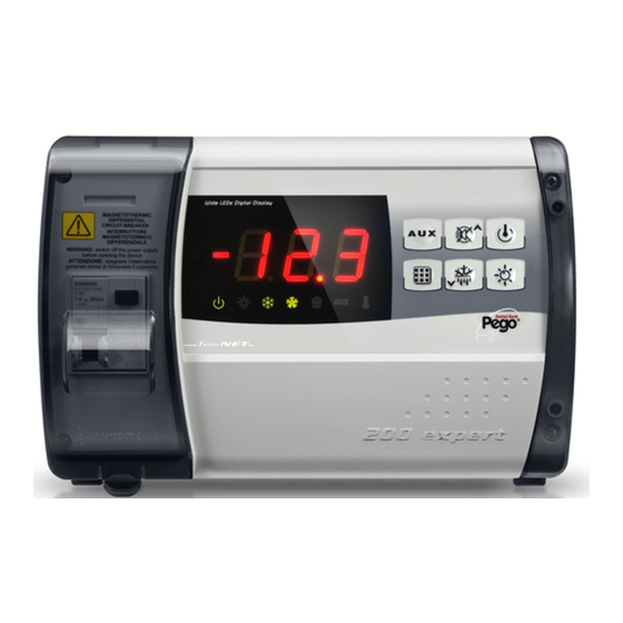
CHAP. 5 – Parameter programming ECP200 EXPERT CHAPTER 5: PARAMETER PROGRAMMING CONTROL PANEL FRONT KEYPAD key: AUXILIARY RELAY CONTROL (on the version with alarm relay controls the relay manual if parameter AU=1) key: UP / MUTE WARNING BUZZER key: STAND BY (if the system shuts down the LED flashes) key: room temperature SETTING key: DOWN / MANUAL DEFROST key: ROOM LIGHT... - Page 13 CHAP. 5 – Parameter programming ECP200 EXPERT LED DISPLAY 1. Cold room temperature / parameters 2. Stand-by (flashes on stand-by. Outputs are deactivated) 3. Room light (flashes if door switch activated) 4. Cold (indicates activation of compressor) 5. Fans 6. Defrosting 7.
- Page 14 CHAP. 5 – Parameter programming ECP200 EXPERT GENERAL To enhance safety and simplify the operator’s work, the ECP200 EXPERT has two programming levels; the first level (Level 1) is used to configure the frequently-modified SETPOINT parameters. The second programming level (Level 2) is for general parameter programming of the various controller work modes.
- Page 15 CHAP. 5 – Parameter programming ECP200 EXPERT LEVEL 1 PROGRAMMING (User level) To gain access to the Level 1 configuration menu proceed as follows: 1. Press the (t) and (u) keys simultaneously and keep them pressed for a few seconds until the first programming variable appears on the display.
- Page 16 CHAP. 5 – Parameter programming ECP200 EXPERT LIST OF LEVEL 1 VARIABLES (User level) VARIABLES MEANING VALUE DEFAULT Temperature difference compared to main SETPOINT 0.2 - 10 °C 2°C Defrost interval (hours) 0 - 24 hours 4 hours End-of-defrost setpoint. Defrost is not executed if the temperature read by the defrost sensor is greater than d2 -35 - 45 °C...
- Page 17 CHAP. 5 – Parameter programming ECP200 EXPERT LEVEL 2 PROGRAMMING (Installer level) To access the second programming level press the UP (t) and DOWN (u) keys and the LIGHT key simultaneously for a few seconds. When the first programming variable appears the system automatically goes to stand-by. 1.
- Page 18 CHAP. 5 – Parameter programming ECP200 EXPERT Cold room sensor value correction -10…+10 0 = NO 0 = NO Compressor protection contact status 1 = NC Compressor safety time for door switch: when the door is opened the evaporator fans shut down and the 0…5 minutes compressor will continue working for time doC, after which it will shut down.
- Page 19 CHAP. 5 – Parameter programming ECP200 EXPERT SWITCHING ON THE ECP200 EXPERT ELECTRONIC CONTROLLER 5.11 After wiring the electronic controller correctly, power up at 230 V AC; the display panel will immediately emit a beep and all the LEDs will come on simultaneously for a few seconds. COMPRESSOR ACTIVATION/DEACTIVATION CONDITIONS 5.12 The ECP200 EXPERT controller activates the compressor when cold room temperature...
- Page 20 CHAP. 5 – Parameter programming ECP200 EXPERT MANUAL DEFROSTING 5.13 To defrost just press the dedicated key (see section 5.2) to activate the elements relay. Defrosting will not take place if the end-of-defrost temperature setting (d2) is lower than the temperature detected by the evaporator sensor. Defrosting ends when the end-of- defrost temperature (d2) or maximum defrost time (d3) is reached.
-
Page 21: Page
CHAP. 6 - Optional kits ECP200 EXPERT CHAPTER 6: OPTIONAL KITS TeleWIN / TeleNET MONITORING/SUPERVISION SYSTEM For connections regarding the TeleWIN-TeleNET / monitoring/supervision system see APPENDIX A.3 a page 26 of this manual and, for the ECP200 EXPERT jumper JP2 as described in 6.2 ON page 22. -
Page 22: Page
CHAP. 6 - Optional kits ECP200 EXPERT ALARM RELAY / TeleWIN-TeleNET SWITCHING Fig. 1: Open the front of the box as described in Chap. 2.3 (page 7): rotate it downwards 180° to gain access to the electronic board. Fig.2: Undo the 6 CPU board fixing screws: remove the board from the frontal part of the box in ABS. -
Page 23: Troubleshooting
CHAP. 7 - Troubleshooting ECP200 EXPERT CHAPTER 7: TROUBLESHOOTING TROUBLESHOOTING In the event of any anomalies the ECP200 EXPERT warns the operator by displaying alarm codes and sounding the warning buzzer inside the control panel. If an alarm is tripped the display will show one of the following messages. - Page 24 Appendices ECP200 EXPERT APPENDICES EC declaration of conformity COSTRUTTORE / MANUFACTURER PEGO SRL Via Piacentina,6b 45030 Occhiobello (RO) - ITALY DENOMINAZIONE DEL PRODOTTO / NAME OF THE PRODUCT MOD.: ECP200 EXPERT IL PRODOTTO E’ CONFORME ALLE SEGUENTI DIRETTIVE CE/THE PRODUCT IS...
- Page 25 Allegati / Appendices ECP200 EXPERT ECP200 EXPERT WIRING DIAGRAM USE AND MAINTENANCE MANUAL Pag. 25 Rev. 04-06...
- Page 26 Allegati / Appendices ECP200 EXPERT TeleWIN / TeleNET NETWORK CONNECTION WIRING DIAGRAM BEFORE CONNECTING UP COMMUTATE THE ALARM RELAY / TELEWIN SWITCHING FUNCTION VIA DIP-SWITCH AS INDICATED CAP. 6.2 Morsettiera di collegamento TeleWIN-TeleNET Terminal block TeleWIN-TeleNET connection USE AND MAINTENANCE MANUAL Pag.
- Page 27 Appendices ECP200 EXPERT Part list REF. DESCRIPTION BOX REAR IN ABS BOX FRONT IN ABS FRONT COVER IN TRANSPARENT POLYCARBONATE BOX FRONT OPENING HINGE BOX CLOSURE SCREWS BOARD FIXING SCREWS MAGNETO-THERMAL CUT-OUT / POWER BREAKER CPU BOARD POLYCARBONATE SCREW COVER TERMINAL FOR EARTH CONNECTIONS USE AND MAINTENANCE MANUAL Pag.
- Page 28 ECP200 EXPERT NOTE USE AND MAINTENANCE MANUAL Pag. 28 Rev. 04-06...
- Page 29 ECP200 EXPERT NOTES USE AND MAINTENANCE MANUAL Pag. 29 Rev. 04-06...
- Page 30 ECP200 EXPERT NOTES USE AND MAINTENANCE MANUAL Pag. 30 Rev. 04-06...
- Page 31 ECP200 EXPERT NOTES USE AND MAINTENANCE MANUAL Pag. 31 Rev. 04-06...
- Page 32 ECP200 EXPERT PEGO S.r.l. Distributore: Via Piacentina, 6/b 45030 OCCHIOBELLO –ROVIGO- Tel : 0425 762906 Fax: 0425 762905 www.pego.it USE AND MAINTENANCE MANUAL Pag. 32 Rev. 04-06 e-mail: info@pego.it...
Need help?
Do you have a question about the ECP 200 EXPERT and is the answer not in the manual?
Questions and answers