
Subscribe to Our Youtube Channel
Related Manuals for Pego PLUS100 AB


Summary of Contents for Pego PLUS100 AB
- Page 1 PLUS100 Use and maintenance manual READ AND KEEP REV. 02-18 ELECTRICAL BOARDS FOR REFRIGERATING INSTALLATIONS...
-
Page 2: Table Of Contents
Page 19 5.10 Level 2 programming Page 20 5.11 List of Level 2 variables Page 22 5.12 Switching on the PLUS100 AB electronic controller Page 22 5.13 Compressor activation/deactivation conditions Page 22 5.14 Cooling cycle activation/deactivation conditions Page 23 5.15... -
Page 3: General
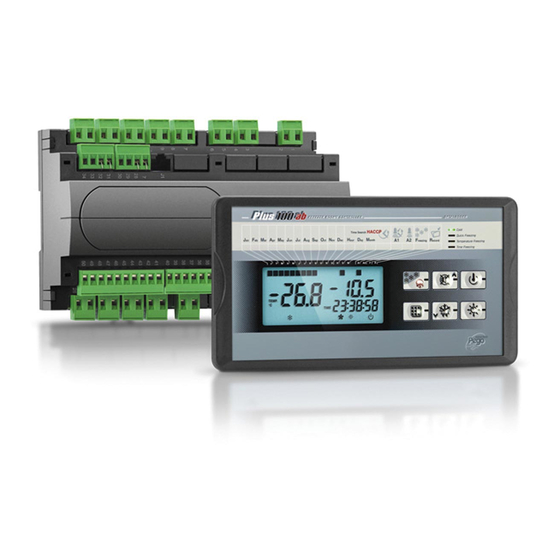
The electronic controllers of the PLUS100 series have been designed to control static or ventilated cold rooms. The PLUS100 AB electronic board allows the user to control all the components on a refrigeration unit. The board allows the user to control and power the main refrigeration system components such as the compressor, evaporator fans, defrosting elements and room light. - Page 4 CHAP. 1 - Introduction PLUS100 AB OVERALL DIMENSIONS IDENTIFICATION DATA The unit described in this manual has, on its side, an ID plate showing all the relevant identification data: • Name of Manufacturer • Code of the electrical board • Serial number •...
-
Page 5: Standard Assembly And Use Kit
1mm STANDARD ASSEMBLY AND USE KIT The PLUS100 AB system is supplied with the following assembly and utilisation items: n°1 console fixing bracket; n°2 temperature sensors (piercing temperature probe not included);... - Page 6 CHAP. 3 - Functions PLUS100 AB CHAPTER 3: FUNCTIONS FUNCTIONS CONTROLLED BY THE PLUS100 AB Display and adjustment of room temperature. Display of skewering sensor temperature. Display of evaporator temperature. System control activation/deactivation. System warnings (sensor error, min-max temperature alarms, compressor safety device).
-
Page 7: Technical Characteristics
CHAP. 4 – Technical characteristics PLUS100 AB CHAPTER 4: TECHNICAL CHARACTERISTICS TECHNICAL CHARACTERISTICS Power supply 230 V~ 10% 50-60Hz Voltage MAX power absorption ~ 7 VA Climatic conditions Working temperature -10 ÷ 60 °C Storage temperature -30 ÷ 70 °C... -
Page 8: Warranty Terms
The intervention service in warranty can be refused when the equipment is modified or transformed. Under no circumstances Pego S.r.l. will be liable for any loss of data and information, costs of goods or substitute services, damage to property, people or animals, loss of sales... -
Page 9: Lcd Areas
CHAP. 5 – Parameter programming PLUS100 AB CHAPTER 5: PARAMETER PROGRAMMING LCD AREAS 1. Display of current month (previous months also remain lit). 2. Indicator/warning LEDs: a. Cold: cooling in progress. b. Quick freezing: rapid freezing in progress. -
Page 10: Control Panel
CHAP. 5 – Parameter programming PLUS100 AB CONTROL PANEL COOLING CYCLE START key (if pressed for a few seconds the cooling cycle starts) UP / MUTE BUZZER ALARM key (if pressed for 5 seconds, together with... -
Page 11: Lcd Display
CHAP. 5 – Parameter programming PLUS100 AB LCD DISPLAY 1. Ambient temperature / parameters (for values greater than +45°C the word HOT is displayed). 2. Evaporator temperature / product sensor temperature / day of current month (see... -
Page 12: Key To Symbols
PLUS100 AB GENERAL To enhance safety and simplify the operator’s work, the PLUS100 AB system has two programming levels; the first level (Level 1) is used to configure the frequently-modified SET-POINT parameters. The second programming level (Level 2) is for general parameter programming of the various controller work modes. -
Page 13: Programming The Type Of Work
CHAP. 5 – Parameter programming PLUS100 AB PROGRAMMING THE TYPE OF WORK (User level) To gain access to the programs menu it is necessary to: 1. Press the key 1 2. Use the arrow keys to select the program (PR1..PR6). - Page 14 CHAP. 5 – Parameter programming PLUS100 AB Program PR2: temperature-based freezing Product freezing program. Freezing ends when the product core temperature reaches At2. A maximum safety time is set on parameter Ab2. When freezing is over the controller automatically goes to storage mode with the ST1 setting. The compressor works continuously.
- Page 15 CHAP. 5 – Parameter programming PLUS100 AB Program PR4: time-based cooling Program for product cooling by time. Cooling ends when the maximum time Ab4 has expired. When cooling is over the controller automatically goes to storage mode with the ST4 setting. ST4 also has the function of regulating the compressor, which stops if room temperature reaches temperature ST4-r1.
- Page 16 PLUS100 AB Program PR6: time-based cooling and freezing Program for product cooling and freezing by time. When room temperature drops below the STS setting the switch from cooling to freezing takes place. Freezing continues until the end of the cycle even in the event of a power cut or a rise in temperature. Freezing ends when the maximum time Ab6 expires.
-
Page 17: Level 1 Programming
CHAP. 5 – Parameter programming PLUS100 AB LEVEL 1 PROGRAMMING (User level) To gain access to the Level 1 configuration menu proceed as follows: 1. Press the () and () keys simultaneously and keep them pressed for a few seconds until the first programming variable appears on the display. -
Page 18: List Of Level 1 Variables
CHAP. 5 – Parameter programming PLUS100 AB LIST OF LEVEL 1 VARIABLES (User level) MEANING VALUES VARIABLE DEFAULT Temperature differential referred to main SETPOINT 1 - 10 °C 2°C Ambient temperature limit during cooling The compressor stops and the fans are activated during the cooling phase if the ambient temperature drops below this differential with respect to 1 - 50 °C... -
Page 19: Level 2 Programming
CHAP. 5 – Parameter programming PLUS100 AB Real-time defrost enable 0 disabled With d0=0 and dFr=1 it is possible to set up to 6 defrosts in real 1 enabled time in a day by using the parameters dF1…dF6 Programming defrost times 00:00:00 - dF1…dF6... -
Page 20: List Of Level 2 Variables
CHAP. 5 – Parameter programming PLUS100 AB LIST OF LEVEL 2 VARIABLES (Installer level) 5.11 VARIABLE MEANING VALUES DEFAULT 0 = normally open Door switch input status 1 = normally closed 0 = Fans working continuously Fan status with compressor off... - Page 21 CHAP. 5 – Parameter programming PLUS100 AB Piercing temperature probe value -10…+10 correction 0 = NO Compressor protection contact status 0 = NO 1 = NC Compressor safety time for door switch: when the door is opened the evaporator 0…5 minutes...
-
Page 22: Switching On The Plus100 Ab Electronic Controller
LEDs will come on simultaneously for a few seconds. COMPRESSOR ACTIVATION/DEACTIVATION CONDITIONS 5.13 The PLUS100 AB controller activates the compressor when cold room temperature exceeds setting+differential (r0); it deactivates the compressor when cold room temperature is lower than the setting. COOLING AND/OR FREEZING CYCLE 5.14... -
Page 23: Manual Defrost
CHAP. 5 - Parameter programming PLUS100 AB MANUAL DEFROSTING 5.15 To defrost just press the dedicated key (see section 5.2) to activate the elements relay. Defrosting will not take place if the end-of-defrost temperature setting (d2) is lower than the temperature detected by the evaporator sensor. Defrosting ends when the end-of- defrost temperature (d2) or maximum defrost time (d3) is reached. -
Page 24: Troubleshooting Guide
CHAPTER 6: TROUBLESHOOTING TROUBLESHOOTING GUIDE In the event of any anomalies the PLUS100 AB system warns the operator by displaying alarm codes and sounding the warning buzzer inside the control panel. If an alarm is tripped the display will show one of the following messages. - Page 25 PLUS100 AB Check fans are working properly. If problem persists contact Fan safety device technical assistance service. Check pressure switches are working properly. Pressure lock-out If problem persists contact technical assistance service. Check the connection between No connection between Console and MASTER the two units.
-
Page 26: Eu Declaration Of Conformity
DEL FABBRICANTE: THIS DECLARATION OF CONFORMITY IS ISSUED UNDER THE EXCLUSIVE RESPONSIBILITY OF THE MANUFACTURER: PEGO S.r.l. Via Piacentina 6/b, 45030 Occhiobello (RO) – Italy – DENOMINAZIONE DEL PRODOTTO IN OGGETTO / DENOMINATION OF THE PRODUCT IN OBJECT MOD.: PLUS100 AB IL PRODOTTO DI CUI SOPRA E’... -
Page 27: Plus100 Ab Connections Diagram
Appendices PLUS100 AB PLUS100 AB CONNECTIONS DIAGRAM Power section Outputs (free-voltage contacts) 1-2 Power supply 230VAC 50/60 Hz 15-16 Freezing solenoid 13-14 Cooling solenoid Analog inputs 11-12 Alarm 27-28 NTC 10K cold room 9-10 Cold room light 29-30 NTC 10K food... - Page 28 Tel. +39 0425 762906 Fax +39 0425 762905 e.mail: info@pego.it – www.pego.it AFTER-SALES ASSISTANCE CENTRE Tel. +39 0425 762906 e.mail: tecnico@pego.it Distributor: USE AND MAINTENANCE MANUAL Page 28 Rev. 02-18 PEGO s.r.l. reserves the right to make amendments to this user manual at any moment.
Need help?
Do you have a question about the PLUS100 AB and is the answer not in the manual?
Questions and answers