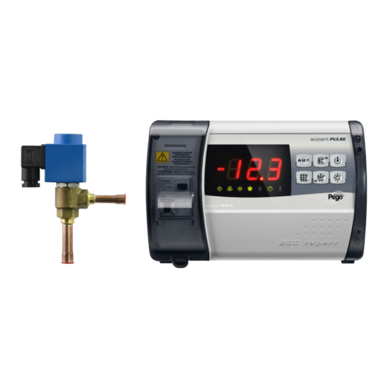
Pego ECP200 EXPERT PULSE Use And Maintenance Manual
Per eev pulse 230v
Hide thumbs
Also See for ECP200 EXPERT PULSE:
- Use and maintenance manual (32 pages) ,
- User and maintenance manual (28 pages) ,
- Use manual (17 pages)

Related Manuals for Pego ECP200 EXPERT PULSE


Summary of Contents for Pego ECP200 EXPERT PULSE
- Page 1 ECP200 EXPERT PULSE ECP200 EXPERT PULSE ECP 200 EXPERT PULSE PER EEV PULSE 230V Use and maintenance manual ENGLISH READ AND KEEP Use and maintenance manual REV. 02-16 ELECTRICAL BOARDS FOR REFRIGERATING INSTALLATIONS Rev. 02-16 Pag. 1...
-
Page 2: Technical Characteristics
Contents ECP200 EXPERT PULSE CONTENTS INTRODUCTION CHAP. 1 Page 3 General Page 4 Product ID codes Page 4 Overall dimensions Page 4 Identification data INSTALLATION CHAP. 2 Page 5 Important information for the installer Page 5 Standard assembly kit Page 6... - Page 3 GENERAL DESCRIZIONE: The ECP200 EXPERT PULSE is a new control panel for cold rooms whith magneto- thermal cut-out switch for the management of the refrigeration system with integrated control of electronic expansion valve ON / OFF with coil to 230 VAC and single-phase compressor up to 2 HP.
- Page 4 Chap. 1 - Introduction ECP200 EXPERT PULSE PRODUCT ID CODES ECP200 EEV controls and manages compressor, defrosting elements, evaporator fans and room light. Aux/Alarms relay Differential magnetothermic circuit breaker 16A Chap. 1 - Introduction Id=300 mA (Id=30 mA on request)
- Page 5 STANDARD EQUIPMENT INCLUDED FOR INSTALLATION AND OPERATION The electronic controller ECP200 EXPERT PULSE, is equipped with the following for installation and operation: • 3 sealing gaskets, to place between the fastening screws and the base of the box;...
- Page 6 Chap. 2 - Installation ECP200 EXPERT PULSE INSTALLING THE ELECTRICAL PANEL Fig. 1: Lift the transparent door that protects the differential magnetothermic circuit breaker and remove the cover for the screws on the right side. Fig. 2: Remove the 4 fastening screws from the front panel of the box.
- Page 7 Chap. 2 - Installation ECP200 EXPERT PULSE Fig. 6: Use the three pre-existing holes to fasten the base of the box with three adequately long screws based on the thickness of the wall that the panel will be installed on. Place a rubber washer (included) between each fastening screw and the base of the box.
-
Page 8: Power Supply
Chap. 3 – Technical features ECP200 EXPERT PULSE CHAPTER 3: TECHNICAL FEATURES TECHNICAL FEATURES Power supply Voltage 230 V~ 10% 50Hz / 60Hz Max. absorbed power (only electronic control) ~ 7 VA Maximum absorption allowed (With all loads connected) - Page 9 PEGO S.r.l. reserves the right to modify its products as it deems necessary without altering its main characteristics. Each new release of a PEGO user manual replaces all the previous ones.
- Page 10 Chap. 5 – Parameter programming ECP200 EXPERT PULSE CHAPTER 5: PARAMETER PROGRAMMING FRONT KEYBOARD KEYBOARD AUXILIARY RELAY COMMAND/VIEWING CURRENT DATE AND TIME Command the relay manually if parameter DO5=3 If pressed for 3 seconds it displays the current date/time (when DO5≠3).
- Page 11 Chap. 5 – Parameter programming ECP200 EXPERT PULSE DOWN / DEFROST When pressed for more than 3 sec. manual defrost is turned on (if the conditions to turn it on subsist). When pressed for more than 3 sec. during a defrost function, this operation will be terminated.
- Page 12 Chap. 5 – Parameter programming ECP200 EXPERT PULSE COMBINATION OF KEYS 1ST LEVEL PROGRAMMING If pressed simultaneously for more than 3 sec. they enable access first level programming menu. A BEEP confirms access to the menu. EXIT FROM PROGRAMMING If pressed simultaneously for more than 3 sec. within any programming menu, they save the settings made exiting the same menu.
- Page 13 Chap. 5 – Parameter programming ECP200 EXPERT PULSE FIRST LEVEL PROGRAMMING (User level) To access the first level configuration menu you must: 1. Simultaneously keep keys ( ) and ( ) pressed down for more than 3 seconds until the first programming variable appears on the display.
- Page 14 Chap. 5 – Parameter programming ECP200 EXPERT PULSE Enabling evaporator defrosting in real time 0 disabled With d0=0 and dFr=1 it is possible to set up to 6 real time defrostings in a single 1 enabled day using parameters d41…d46 Programming evaporator defrosting times.
- Page 15 Chap. 5 – Parameter programming ECP200 EXPERT PULSE Operating time ON for the compressor in case of broken ambient probe (Emergency function) 0…240 min With CE1=0 the emergency function with an E0 error 0 = disabled remains disabled, the compressor stays off and defrosting is inhibited in order to preserve the residual cold.
- Page 16 Chap. 5 – Parameter programming ECP200 EXPERT PULSE -6= Stop defrosting from remote (N.C.) (The down impulse front is taken) -7= Pump-down pressure switch (N.C.) 5= automatic auxiliary relay managed by the StA temperature set referred to the st0 probe with a 2°C differential (this...
- Page 17 Chap. 5 – Parameter programming ECP200 EXPERT PULSE 0 = displays only the set point and allows you to silence the alarms 1 = displays the set point, allows you to silence the alarms, + defrost + light + aux key + menu with read-...
- Page 18 Chap. 5 – Parameter programming ECP200 EXPERT PULSE 3rd LEVEL PROGRAMMING (EEV PARAMETERS) 5.10 To access third level programming, keep the UP ( ) and STAND-BY keys pressed for more than 3 seconds. When the first programming variable appears, the system automatically switches to stand-by.
- Page 19 Chap. 5 – Parameter programming ECP200 EXPERT PULSE Proportional band (gain) PID overheating adjustment. 1...100% 0-500 sec Integral time PID overheating adjustment algorithm 100 sec 2-second steps 0.0-10.0 sec Derivative time PID overheating adjustment algorithm 2.0 sec 0.1-second steps Percentage of the EEV valve opening in case of error with probes S3 or S4.
- Page 20 Chap. 5 – Parameter programming ECP200 EXPERT PULSE Delay in activating the LSH alarm: the LSH overheating alarm is signalled only after it has been active for the amount of the SHd time. In case of an LSH alarm, the valve closing is nevertheless instantaneous;...
- Page 21 Chap. 5 – Parameter programming ECP200 EXPERT PULSE Delay in activating the LOP alarm: the LOP alarm is signalled only once the LOP protection has been active for the amount of the LOd time. The alarm is self-restoring when "Temp.S5" ≥ LOP (0 ÷...
- Page 22 Chap. 5 – Parameter programming ECP200 EXPERT PULSE QUICK VARIABLES VIEWING MENU (READ ONLY) 5.13 During system start-up it can be useful to check the reading of the various probes or a number of values in a simple fashion, or optimise the process.
- Page 23 Chap. 5 – Parameter programming ECP200 EXPERT PULSE THERMOSTAT OPERATING MODE 5.15 The mOd variable allows you to choose the operating mode for the thermostat, in particular: CHILL CALL MODE The DO1 output is activated when the temperature measured by the Ambient probe reaches or exceeds the SET POINT+r0 value and stays active until the temperature falls below the SET POINT.
- Page 24 Chap. 5 – Parameter programming ECP200 EXPERT PULSE MANUALLY FORCE TERMINATE DEFROST IN PROGRESS 5.19 When defrost is in progress press the DOWN button for 4 seconds to force defrost in progress to terminate. When terminating defrost manually the drip phase is also skipped.
- Page 25 NET CONFIGURATION WITH MODBUS-RTU PROTOCOL For RS485 connections with Modbus-RTU protocol, to enable RS485 output follow the scheme below. Refer to MODBUS-RTU_ECP200T1 user manual (available on Pego Internet web site) for MODBUS-RTU communication protocol specification. Use and maintenance manual Rev. 01-16...
- Page 26 Chap. 7 – Diagnostics ECP200 EXPERT PULSE CHAPTER 7: DIAGNOSTICS DIAGNOSTICS In case of anomaly, the ECP200 EXPERT controller will alert the operator through the alarm codes displayed on the screen and with an acoustic signal emitted by a buzzer (if included).
- Page 27 Chap. 7 – Diagnostics ECP200 EXPERT PULSE Maximum temperature alarm. The words EH flash alternately with the temperature (See parameter A2) Low overheating temperature alarm Maximum saturated evaporation temperature alarm referred to sensor S4 Minimum saturated evaporation temperature alarm referred to...
- Page 28 ECP200 EXPERT PULSE APPENDICES EC declaration of conformity COSTRUTTORE / MANUFACTURER: PEGO S.r.l. Via Piacentina, 6/b 45030 Occhiobello (RO) – Italy – Tel. (+39) 0425 762906 Fax. (+39) 0425 762905 DENOMINAZIONE DEL PRODOTTO / NAME OF THE PRODUCT: MOD.: ECP200 EXPERT EEV IL PRODOTTO E’...
- Page 29 Appendices ECP200 EXPERT PULSE CONNECTIONS DIAGRAM Use and maintenance manual Rev. 01-16 Pag. 29...
- Page 30 Appendices ECP200 EXPERT PULSE Part list LEGEND REF. DESCRIPTION BOX REAR IN ABS BOX FRONT IN ABS FRONT COVER IN TRANSPARENT POLYCARBONATE BOX FRONT OPENING HINGE BOX CLOSURE SCREWS BOARD FIXING SCREWS MAGNETO-THERMAL CUT-OUT / POWER BREAKER CPU BOARD POLYCARBONATE SCREW COVER...
- Page 31 Appendices ECP200 EXPERT PULSE NOTE Use and maintenance manual Rev. 01-16 Pag. 31...
- Page 32 ECP200 EXPERT PULSE PEGO S.r.l. Distributor: Via Piacentina, 6/b 45030 OCCHIOBELLO –ROVIGO- Tel : 0425 762906 Fax: 0425 762905 www.pego.it Use and maintenance manual Pag. 32 Rev. 01-16 e-mail: info@pego.it...
Need help?
Do you have a question about the ECP200 EXPERT PULSE and is the answer not in the manual?
Questions and answers