Pego ECP200 EXPERT PULSE Use And Maintenance Manual
Per eev pulse 230v
Hide thumbs
Also See for ECP200 EXPERT PULSE:
- Use and maintenance manual (32 pages) ,
- User and maintenance manual (28 pages) ,
- Use manual (17 pages)
Table of Contents

Related Manuals for Pego ECP200 EXPERT PULSE


Summary of Contents for Pego ECP200 EXPERT PULSE
- Page 1 ECP200 EXPERT PULSE ECP200 EXPERT PULSE ECP 200 EXPERT PULSE PER EEV PULSE 230V Use and maintenance manual ENGLISH READ AND KEEP Rel. Software: 4 ELECTRICAL BOARDS FOR REFRIGERATING INSTALLATIONS REV. 03-18 Use and maintenance manual...
-
Page 2: Table Of Contents
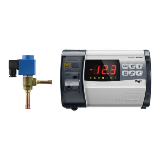
Contents ECP200 EXPERT PULSE CONTENTS INTRODUCTION CHAP. 1 Page 3 General Page 4 Product ID codes Page 4 Overall dimensions Page 4 Identification data INSTALLATION CHAP. 2 Page 5 Important information for the installer Page 5 Standard assembly kit Page 6... - Page 3 GENERAL DESCRIPTION: The ECP200 EXPERT PULSE is a new control panel for cold rooms with magneto-thermal cut-out switch for the management of the refrigeration system with integrated control of electronic expansion valve ON / OFF with coil to 230VAC and single-phase compressor up to 2 HP.
-
Page 4: Overall Dimensions
Chap. 1 - Introduction ECP200 EXPERT PULSE PRODUCT ID CODES ECP200 EEV Controls and manages compressor, defrosting elements, evaporator fans and room light. Aux/Alarms relay. It is compatible with the most common 230VAC ON/OFF electronic expansion valves. Evaporator superheat control. - Page 5 STANDARD EQUIPMENT INCLUDED FOR INSTALLATION AND OPERATION The electronic controller ECP200 EXPERT PULSE, is equipped with the following for installation and operation: • 3 sealing gaskets, to place between the fastening screws and the base of the box;...
- Page 6 Chap. 2 - Installation ECP200 EXPERT PULSE INSTALLING THE ELECTRICAL PANEL Fig. 1: Lift the transparent door that protects the differential magneto thermic circuit breaker and remove the cover for the screws on the right side. Fig. 2: Remove the 4 fastening screws from the front panel of the box.
- Page 7 ECP200 EXPERT PULSE. Every time repair and/or maintenance is performed the panel must be disconnected from the power supply and from all possible inductive and power loads that it may be connected to;...
- Page 8 Chap. 3 – Technical features ECP200 EXPERT PULSE CHAPTER 3: TECHNICAL FEATURES TECHNICAL FEATURES Power supply Voltage 230V~ 10% 50/60Hz Max. absorbed power (only electronic control) ~ 7 VA Maximum absorption allowed (With all loads connected) Climatic Conditions Working temperature -5 ÷...
-
Page 9: Warranty
The intervention service in warranty can be refused when the equipment is modified or transformed. Under no circumstances Pego S.r.l. will be liable for any loss of data and information, costs of goods or substitute services, damage to property, people or animals, loss of sales... - Page 10 Chap. 5 – Parameter programming ECP200 EXPERT PULSE CHAPTER 5: PARAMETER PROGRAMMING FRONT KEYBOARD KEYBOARD AUXILIARY RELAY COMMAND/VIEWING CURRENT DATE AND TIME Command the relay manually if parameter AU1=2 ...
- Page 11 Chap. 5 – Parameter programming ECP200 EXPERT PULSE DOWN / DEFROST When pressed for more than 3 seconds manual defrost is turned on (if the conditions to turn it on subsist). When pressed for more than 3 seconds during a defrost function, this operation will be terminated.
- Page 12 Chap. 5 – Parameter programming ECP200 EXPERT PULSE COMBINATION OF KEYS 1ST LEVEL PROGRAMMING If pressed simultaneously for more than 3 seconds they enable access to first level programming menu. EXIT FROM PROGRAMMING If pressed simultaneously for more than 3 seconds within any programming menu, they save the settings made exiting the same menu.
- Page 13 Chap. 5 – Parameter programming ECP200 EXPERT PULSE FIRST LEVEL PROGRAMMING (User level) To access the first level configuration menu you must: 1. Simultaneously keep keys ( ) and ( ) pressed down for more than 3 seconds until the first programming variable appears on the display.
- Page 14 Chap. 5 – Parameter programming ECP200 EXPERT PULSE Programming evaporator defrosting times. It is possible to set up to 6 times for defrosting episodes. … The time is in the HH.M format where HH represents the hour and M 00.0 ÷ 23.5 tens of minutes (Ex.
- Page 15 Chap. 5 – Parameter programming ECP200 EXPERT PULSE 0 = current temperature 1 = temperature at the start of the Display viewing during Defrost defrost 2 = “DEF” Net address for connection to TeleNET 0 ÷ 31 (with SEr=0) supervision system or Modbus 1 ÷...
- Page 16 Chap. 5 – Parameter programming ECP200 EXPERT PULSE -6 (NC) = relay de-energized during stand-by. -5 (NC) = Contact for casing element control (AUX relay closed with compressor output inactive). This output also remains active when the QE is in STAND-BY.
- Page 17 Chap. 5 – Parameter programming ECP200 EXPERT PULSE 8 = Night mode digital input (energy saving, N.O.) 7 = Stop defrosting remotely (N.O.) (reads rising edge of impulse) 6 = Start defrosting remotely (N.O.) (reads rising edge of impulse) 5 = Stand-by remotely (N.O.) (In order to indicate Stand-By mode, the display shows ‘In5’...
- Page 18 Chap. 5 – Parameter programming ECP200 EXPERT PULSE 3rd LEVEL PROGRAMMING (EEV PARAMETERS) 5.10 To access third level programming, keep the UP () and STAND-BY keys pressed for more than 3 seconds. When the first programming variable appears, the system automatically switches to stand-by.
- Page 19 Chap. 5 – Parameter programming ECP200 EXPERT PULSE During the Start phase the EEV valve opens as far as the ÷ 100% ESO percentage and for the ESt time During the Start phase. ÷ Edt tens of seconds tens of In this phase the MOP, LOP, LSH alarms are disabled.
- Page 20 Chap. 5 – Parameter programming ECP200 EXPERT PULSE MOP threshold (Maximum saturated evaporation Temperature referred to the sensor S5) This represents the maximum evaporation pressure, expressed in saturated degrees, and activates the MOP (LOP+1) ÷ +45°C +45℃ protection when it is exceeded (EMO parameter). If the...
-
Page 21: Temperature Table For Refrigerant Fluids
Chap. 5 – Parameter programming ECP200 EXPERT PULSE Loading default settings based on the EEV variable: 5.12 EEV = 2 EEV = 3 EEV = 4 EEV = 5 (TN COLD ROOM (BT COLD ROOM (control of COLD (control of COLD... - Page 22 Chap. 5 – Parameter programming ECP200 EXPERT PULSE QUICK VARIABLES VIEWING MENU (READ ONLY) 5.14 During system start-up it can be useful to check the reading of the various probes or a number of values in a simple fashion, or optimise the process.
-
Page 23: Manual Activation Of Defrost
Chap. 5 – Parameter programming ECP200 EXPERT PULSE THERMOSTAT OPERATING MODE 5.16 CHILL CALL MODE The DO1 output is activated when the temperature measured by the Ambient probe reaches or exceeds the SET POINT+r0 value and stays active until the temperature falls below the SET POINT. -
Page 24: Defrost With Heater And Temperature Control
Chap. 5 – Parameter programming ECP200 EXPERT PULSE MANUALLY FORCE TERMINATE DEFROST IN PROGRESS 5.20 When defrost is in progress press the DOWN button for 3 seconds to force defrost in progress to terminate. When terminating defrost manually the drip phase is also skipped. -
Page 25: Telenet Monitoring / Supervision System
WARNING: During configuration, at entry “Module” select "Instrument ECP200EEV ". NET CONFIGURATION WITH MODBUS-RTU PROTOCOL For RS485 connections with Modbus-RTU protocol, to enable RS485 output follow the scheme below. Refer to MODBUS-RTU_ECP200EEV user manual (available on Pego web site) for MODBUS-RTU communication protocol specification. Use and maintenance manual... - Page 26 Chap. 7 – Diagnostics ECP200 EXPERT PULSE CHAPTER 7: DIAGNOSTICS DIAGNOSTICS In case of anomaly, the ECP200 EXPERT EEV controller will alert the operator through the alarm codes displayed on the screen and with an acoustic signal emitted by a buzzer (if included).
- Page 27 Chap. 7 – Diagnostics ECP200 EXPERT PULSE Check that the compressor is working properly. Minimum temperature alarm Sensor not reading The words EL flash alternately with the temperature temperature properly or (See parameter A1) compressor start/stop control not working.
-
Page 28: Eu Declaration Of Conformity
DEL FABBRICANTE: THIS DECLARATION OF CONFORMITY IS ISSUED UNDER THE EXCLUSIVE RESPONSIBILITY OF THE MANUFACTURER: PEGO S.r.l. Via Piacentina 6/b, 45030 Occhiobello (RO) – Italy – DENOMINAZIONE DEL PRODOTTO IN OGGETTO / DENOMINATION OF THE PRODUCT IN OBJECT MOD.: ECP200 EXPERT EEV IL PRODOTTO DI CUI SOPRA E’... -
Page 29: Connection Diagram
Appendices ECP200 EXPERT PULSE CONNECTIONS DIAGRAM Use and maintenance manual... -
Page 30: Part List
Appendices ECP200 EXPERT PULSE PART LIST LEGEND REF. DESCRIPTION BOX REAR IN ABS BOX FRONT IN ABS FRONT COVER IN TRANSPARENT POLYCARBONATE BOX FRONT OPENING HINGE BOX CLOSURE SCREWS BOARD FIXING SCREWS MAGNETO-THERMAL CUT-OUT / POWER BREAKER CPU BOARD POLYCARBONATE SCREW COVER... - Page 31 ECP200 EXPERT PULSE NOTES Use and maintenance manual...
- Page 32 Tel. +39 0425 762906 Fax +39 0425 762905 e.mail: info@pego.it – www.pego.it AFTER-SALES ASSISTANCE CENTRE Tel. +39 0425 762906 e.mail: tecnico@pego.it Distributor: Use and maintenance manual PEGO s.r.l. reserves the right to make amendments to this user manual at any moment.
Need help?
Do you have a question about the ECP200 EXPERT PULSE and is the answer not in the manual?
Questions and answers