
Related Manuals for Pego VISION TOUCH PAN


Summary of Contents for Pego VISION TOUCH PAN
- Page 1 VISION TOUCH PAN User and maintenance manual ENGLISH READ AND KEEP Rel. Software: VT_PAN_2_0_0_3 REV. 01-19 ELECTRICAL BOARDS FOR REFRIGERATING INSTALLATIONS...
- Page 2 VISION TOUCH PAN Thank you for choosing PEGO'S VISION TOUCH PAN controller. Reading this manual thoroughly will guide you through proper installation and better use of the various features. We therefore recommend keeping this manual near the controller to make use of it during the device installation, configuration and use.
-
Page 3: Table Of Contents
VISION TOUCH PAN CONTENTS INTRODUCTION CHAPTER 1 Page 5 General information Page 6 Product identification codes Page 7 Overall dimensions Page 7 Identification data Page 8 Technical features INSTALLATION CHAPTER 2 Page 9 General rules for the installer Page 9... - Page 4 VISION TOUCH PAN PARAMETERS CHAPTER 8 Access to the “Parameters” menu Page 48 Page 49 Description of parameters setting page Page 50 Parameters menu items list Page 52 8.3.1 Process adjustment Page 53 8.3.2 Defrost cycles Page 55 8.3.3 Ventilation Page 56 8.3.4...
-
Page 5: General Information
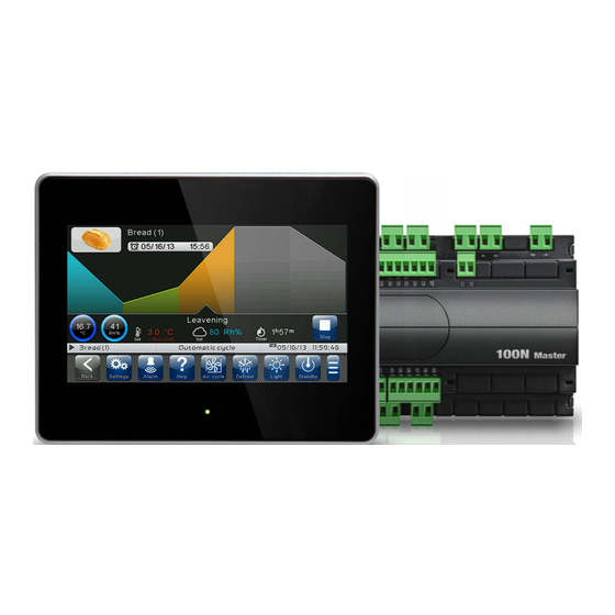
The system consists of the 100N MASTER3 unit, on which all the electrical connections are made, and the VISION TOUCH PAN control console, equipped with 7'' TFT display with capacitive touch screen combined with a highly advanced software and a highly user friendly interface that allows easy use. -
Page 6: Product Identification Codes
VISION TOUCH PAN GENERAL CHARACTERISTICS OF THE CONTROLLER: 7'' TFT display with high resolution (800x480 WVGA), LED backlighting and capacitive touch screen. Front with 1,1 mm chemically treated glass. Ability to reverse the viewing angle of the display to ensure the possibility of mounting at any height. -
Page 7: Overall Dimensions
IDENTIFICATION DATA The device described in this manual has, on the side of 100N MASTER3 and on the back of the VISION TOUCH PAN console, a plate bearing its identification data: • Name of Manufacturer • Code of the device •... -
Page 8: Technical Features
3A 240V (AC3) Dimensional features Dimensions 100N MASTER3 121.50 mm x 71 mm x 175 mm (HxDxL) Dimensions VISION TOUCH PAN 151 mm x 44 mm x 191 mm (HxDxL) Insulation and mechanical properties Degree of protection of display IP65... -
Page 9: General Rules For The Installer
11. When using the console at low temperatures there could be a visible slow down in the response from the display; this can be considered normal. STANDARD EQUIPMENT FOR ASSEMBLY AND USE The VISION TOUCH PAN electronic controller is provided with the following for assembly and use: • 2 temperature probes;... -
Page 10: Installation And Assembly
VISION TOUCH PAN INSTALLATION AND ASSEMBLY Fig. 1: Install the 100N MASTER3 module on the DIN guide and close the bottom clamps to hold it in place. 177mm Fig. 2: VISION TOUCH console drilling template. Fig. 3: Configure properly the side switch (if present) to reverse the viewing angle of the display. - Page 11 VISION TOUCH PAN Fig. 4: Fasten the VISION TOUCH console by means of the four media to be inserted in their specific seats. Tighten each screw until the entire border front of the console rests on the panel. USER AND MAINTENANCE MANUAL Pag.
-
Page 12: Electrical Connections
VISION TOUCH PAN CHAPTER 3: ELECTRICAL CONNECTIONS Following are the electrical connections of the controller divided by type. The configurations of the inputs and outputs shown below are set by default but can be changed to suit your needs. The connection between the console and 100N MASTER3 has two possible variants based on the distance between the two components. - Page 13 VISION TOUCH PAN 2) Connection between the console and 100N MASTER3 with distance within 500m: Connect the ground to the GND terminal of M2 in the console (functional ground). This connection helps to limit the effects of the electromagnetic noise on the control system. The...
- Page 14 VISION TOUCH PAN DIGITAL OUTPUT CONNECTION ON 100N MASTER3 POSSIBLE CONFIGURATIONS ÷ DIGITAL OUTPUTS DO1 DO12 Access menu: Parameters > Configure I/O > Digital outputs 0 = Disabled 1 = Hot 2 = Cold 3 = Fan high speed 4 = Fan low speed...
- Page 15 VISION TOUCH PAN DIGITAL INPUT CONNECTION ON 100N MASTER3 POSSIBLE CONFIGURATIONS ÷ DIGITAL INPUTS DI1 DI12 Access menu: Parameters > Configure I/O > Digital inputs 0 = Disabled 1 = Door switch 2 = Alarm 3 = Stand-by 4 = Disable hot...
- Page 16 VISION TOUCH PAN ANALOGUE INPUT CONNECTION ON 100N MASTER3 POSSIBLE CONFIGURATIONS ÷ ANALOGUE INPUTS AI1 Access menu: Parameters >Configure I/O >Analogue inputs 0 = Disabled 1 = Ambient temperature (NTC) 2 = Evaporator temperature (NTC) 3 = Ambient humidity probe (4-20mA)
-
Page 17: Ethernet Connection On Vision Touch
VISION TOUCH PAN ANALOGUE OUTPUT CONNECTION ON 100N MASTER3 POSSIBLE CONFIGURATIONS ÷ ANALOGUE OUTPUTS AO1 Access menu: Parameters >Configure I/O >analogue outputs 0 = Disabled 1 = Speed of the evaporator fans 2 = Humidifier regulation DESCRIPT. TYPE OF ANALOGUE... -
Page 18: Connection To Rs-485 For Telenet Or Modbus- Rtu
VISION TOUCH PAN CONNECTION TO RS-485 FOR TELENET OR MODBUS-RTU Connect the earth to the GND terminal of M3 in the console (functional earth). This connection helps to limit the effects of the electromagnetic noise control system. The ground connection must be made in a manner consistent with applicable regulations. -
Page 19: Switching On
VISION TOUCH PAN CHAPTER 4: SWITCHING ON COMMISSIONING When the controller is switched on for the first time, the "Language Selection" and "time and date setting" pages of the system are displayed to facilitate the user in starting up the controller. -
Page 20: Switch-On Controller
VISION TOUCH PAN SWITCH-ON CONTROLLER Every time the controller is switched on, an information pop-up is displayed with the starting date and time, requesting the user to acquire the information by pressing "OK". This allows to verify the return from an electrical blackout. -
Page 21: User Interface
CHAPTER 5: USER INTERFACE This section illustrates the features and instructions for using the display, the light indicators and the buttons making up the user interface of the VISION TOUCH PAN, and therefore represent an essential requirement to correctly program and configure the controller. -
Page 22: Main Display
VISION TOUCH PAN MAIN DISPLAY The section of the main display views the work and setting pages based on the position (for example Home, Configuration, phase). A detailed description of the various pages will be made further on in this manual. -
Page 23: Button Bar
VISION TOUCH PAN BUTTON BAR The Button Bar is at the bottom of the display and views the main operating buttons and their status. It is always present except when, in some rare cases, it is temporarily hidden to fully exploit the display. - Page 24 VISION TOUCH PAN Description of buttons in Button Bar: BACK: Inside a menu or level: Go back to previous level or menu. In a HOME page: Go back to the previous Home page. Indietro If held for longer than 3 seconds: Go back to HOME1 page...
-
Page 25: Gesture
VISION TOUCH PAN GESTURE The Vision Touch, aside from normal pressing of keys, on some pages supports gestures which allow the user a more natural and therefore simpler interaction. Change Home Page: On one Home page, move your finger to the left or to the right to pass from one Home page to the next one or to the previous one. - Page 26 VISION TOUCH PAN Change parameters with roll selection: Move your finger up or down by one roll to change its value. (Suggestion: move your finger starting from the outside of the roll and pass through it completely). If the value you are trying to set is not allowed and is not included in the range of the variables, the background of the roll will turn red for an instant indicating that the action is not allowed.
- Page 27 VISION TOUCH PAN "Edit" mode in Home 1 and 2 pages: When you are on one of the Home pages, touch the screen at a point which is not a button for more than three straight seconds to enter edit mode of the page itself. To exit this mode, press the "Back" button or wait for the automatic exit after one minute of inactivity.
-
Page 28: Home Pages
VISION TOUCH PAN CHAPTER 6: HOME PAGES The "Home" pages are the main interface of the controller from whence it is possible to access the mostly used features. They are divided as follows: MANUAL MODE (HOT OR COLD) AUTOMATIC PROGRAMS... - Page 29 VISION TOUCH PAN MANUAL MODE - Select the manual mode, Temperature/Humidity Management The "MANUAL MODE" page allows the manual mode that is to be used (hot/cold) to be selected, the Temperature and Humidity settings to be displayed and modified and access to the recipes page by pressing the Select Program button.
- Page 30 VISION TOUCH PAN Temperature adjustment dial: Displays all that regards temperature adjustment, in particular: • The temperature set point (can be modified by pressing the dial for 3 seconds). • Adjustment probe temperature measurement. • The status of the call (Cold / Hot / No call).
- Page 31 VISION TOUCH PAN Multifunction data visualization dial: it consists of two parts which, when touched, cyclically alternate the data displayed. The following are the various screens and their related meanings. Note: Some data is only viewed if the relative function is enabled in the configuration parameters.
-
Page 32: Manual Mode: Modify The Temperature/Humidity Setpoint And Fan Speed
VISION TOUCH PAN MANUAL MODE – Modify the Temperature/Humidity setpoint, the fan speed “Modify setpoint” mode on the MANUAL MODE page: Touch one of the adjustment dials on the screen (Temperature or humidity) for more than three consecutive seconds. Once you have entered the edit mode, it is possible to change the humidity and temperature Set Points currently in use by rotating the Wheel clockwise to increase or anti- clockwise to decrease the value of the Set Point to be modified. - Page 33 VISION TOUCH PAN Evaporator fan speed selection buttons Evaporator fan speed selection buttons: Evaporator fans high speed. Evaporator fans low speed. Evaporator fans with 0-10V output. 100 % This button is only displayed if the EFa parameter = 1. Press + or - to increase or decrease the evaporator fan speed.
-
Page 34: Automatic Programs Display, Create, Start And Edit
VISION TOUCH PAN AUTOMATIC PROGRAMS – Display, create, start and edit. Button to access the automatic programs display page: Program selection: Press this button to enter the automatic program management and display page. Program The "Program list" allows complete management of the programs (Recipes): view the list, create, edit, delete and start the program. - Page 35 VISION TOUCH PAN Bar to create a new program: Allows a new program to be created; once pressed, it prompts to enter the name using the keyboard and then the configuration of the phases and the general settings. The phase setting pages of a new program are the same as those used to Modify a program.
- Page 36 VISION TOUCH PAN AUTOMATIC PROGRAMS - description of the Program Phases There can be up to 9 phases in a program, split as follows: Accumulation 1 (Pre-cooling/chilling) [-18°C/-10°C]: In this phase, the temperature is brought to a very low value to prepare the cell for the product to be inserted.
- Page 37 VISION TOUCH PAN AUTOMATIC PROGRAMS - Add/Edit Program Phases The button appears when the program is stopped and the PROGRAM LIST is accessed. Edit program: Enters the program edit page. Edit Change the generic settings of Enabling the single phases.
- Page 38 VISION TOUCH PAN The buttons appear when the edit page of a recipe is accessed. These are overlapped with the CONFIRM and CANCEL buttons if at least one configuration of the program is edited. Delete program. Deletes the program from the memory of the device.
- Page 39 VISION TOUCH PAN General option configuration page of program 2/3: Select icon: Notice (popup) at program end: This button accesses the database of The user is informed of the end of a program icons that can be used to identify a by means of a notice Pop-up.
- Page 40 VISION TOUCH PAN General option configuration page of program 3/3: Defrosting when leavening begins: if enabled, a defrosting process is performed at the beginning of the leavening phase. Oven advance ignition: the switch enables the oven advance ignition control. Configures the advance ignition (hours and minutes) of the oven with respect to the end of the recipe.
- Page 41 VISION TOUCH PAN Press the button in the bottom left corner of each phase to access the phase configuration page. Phase configuration page 1/2: Name of Active functions Confirm and cancel the selected phase in this phase modifications buttons Buttons for moving between...
- Page 42 VISION TOUCH PAN Phase configuration page 2/2: Fans: Fan start-up mode control. Evaporator fan speed selection in Temperature threshold selected phase. for humidity control: If the 0-10V output is selected for fan speed enables the humidity control only regulation (parameter EFa=1 in the Ventilation...
- Page 43 VISION TOUCH PAN Phase configuration page 3/3 (only for leavening): An additional configuration page is present during the leavening phases, on which the gradual setpoint increase function can be enabled for a temperature ramp to be obtained. With this function active, the phase duration time becomes the time required to reach the set temperature.
-
Page 44: Automatic Programs: Automatic Cycle
VISION TOUCH PAN AUTOMATIC PROGRAMS - Automatic cycle The "automatic cycle" is displayed automatically after a program is started, if the prepared product time is correct. At the end of the program or when the STOP button is pressed, the "Manual mode"... - Page 45 VISION TOUCH PAN Summary bar of the current phase: Tap the summary bar of the current phase to access the temperature and humidity setpoint page. "Edit setpoints" mode on the CURRENT PROGRAM (SETPOINT) page: Touch one of the adjustment dials on the screen (temperature or humidity) for more than three consecutive seconds.
- Page 46 VISION TOUCH PAN At this point a graph with the trends of the temperature and humidity setpoints set in each phase of the program will be displayed. It is possible to view the complete configuration of a phase (and modify the setpoints, if the user is enabled), by pressing the button.
-
Page 47: Access Levels To Parameters (User/ Installer)
VISION TOUCH PAN CHAPTER 7: ACCESS LEVELS Access levels to parameters (User/ installer) The controller has two access levels to the parameters and to the functions: “User” and “Installer”. The default setting is User that has a parameter menu that can be customised by the installer. -
Page 48: Access To The "Parameters" Menu
VISION TOUCH PAN CHAPTER 8: PARAMETERS Access to Parameters menu Press the "Parameters" button in the Button Bar to access the control parameters setting menu. PARAMETERS: Enters the parameter setting menu Parametri Probes calibration Process regulation Communication RS485 Defrost Fans... -
Page 49: Description Of Parameters Setting Page
VISION TOUCH PAN Description of parameter setting page Press the "Parameters" button in the Button Bar to access the controller parameters setting menu. Each sub-menu contains the name of the variables that can be set, a brief description in the selected language and the currently set value. -
Page 50: Configure Pan
Web server Configurazione Web server 8.3.9 Mail E-mail configuration 8.3.10 PEGO 8.3.11 Enabling communication with a PEGO humidifier humidifier Language 8.3.12 Control unit language setting Date and time settings Date and time 8.3.13 (not accessible while a program is running) General settings 8.3.14... -
Page 51: Software
VISION TOUCH PAN Management of control software reset and update, Software 8.3.15 device parameters export/import from USB/SD VISION TOUCH PAN device information Info 8.3.16 (software version, memory occupied) Management of protection level: Password 8.3.17 user/installer access, menu configuration Digital/analogue inputs/outputs test, touchscreen 8.3.18... - Page 52 VISION TOUCH PAN Process adjustment 8.3.1 “Process adjustment” allows setting the differentials and the temperature and humidity neutral area of the PAN. The “Process adjustment” menu can be accessed from the main Configuration page (“Parameters” Button). The display of this item can be set in the “Password” sub-menu =>...
- Page 53 VISION TOUCH PAN Defrosts 8.3.2 Defrosts are managed with the parameters d4, d5, d6, d7, F5 which define their intervals, the maximum duration, the defrost end temperature, dripping and fan stopping. To switch defrost on manually, just press the “Defrost” button. Defrosting will not be activated if the defrost end temperature (d6) is set lower than the temperature detected by the evaporator probe.
- Page 54 VISION TOUCH PAN For the correct management of the plant, it will be the responsibility of the installer to use the defrost output, that must allow the opening of the cycle inversion electrovalve and the closing of the liquid electrovalve.
- Page 55 VISION TOUCH PAN FAN blocking TEMPERATURE The fans do not switch on if the value of the temperature read by the evaporator probe is higher than the value of this parameter. The block is deactivated when the evaporator probe -45,0 ÷ 99,0 °C +99,0 °C...
- Page 56 VISION TOUCH PAN Air change 8.3.4 The air changes can be enabled with parameter rA. Cyclical air exchange cycles, which can be set using the rA parameter, can be performed. The duration of the air change is defined by parameter drA. During air change, hot, cold, humidity and dehumidification do not activate.
- Page 57 VISION TOUCH PAN Machine protection 8.3.6 “Machine protection” contains the safety parameters to manage the system. One can set the minimum interval between compressor activations, the dehumidification limit time and which action must be performed in the event the dehumidification limit time Timeout intervenes.
- Page 58 VISION TOUCH PAN Probe calibration 8.3.7 The “Probes calibration” menu allows to correct the value measured by the room/outside temperature and humidity probes and to correct the value measured by the evaporator probe. The menu can be accessed from the main Configuration page (“Parameters”...
- Page 59 VISION TOUCH PAN Web server 8.3.9 The "Web server" menu allows setting the Web server configuration. This menu is accessible from the Main Configuration page (“Parameters” Button). The visibility of this item can be set in the submenu "Password" => “Configure user level menu” and by selecting the “Web server”...
- Page 60 VISION TOUCH PAN Settings page Changes are applied when the “Confirm” button is pressed Enable / disable DHCP Configure Port Configure IP address Configure Netmask Configure Gateway - DHCP: enable / disable configuration request to the DHCP server. If enabled, the IP address associated with Vision Touch is assigned by the DHCP server (if it is present on the local network).
- Page 61 VISION TOUCH PAN The page “User name” allows configuring the Username to be used during login on the Vision touch Web page (the password coincides with the Vision Touch Installer password). Username Web Password Browser Web (default: adminlogin) (default: 100) USER AND MAINTENANCE MANUAL Pag.
- Page 62 Web page, regardless of the type of user (user or admin) that accesses the Web page. Info page The "Info Page" allows checking the current Web configuration of the Vision Touch PAN. DHCP: DHCP assignment status Host: name used in the web browser address bar (linked to the serial number)
- Page 63 VISION TOUCH PAN Mail 8.3.10 The “Mail” menu allows setting the alarm mail configuration. The menu can be accessed from the main Configuration page (“Parameters” Button). The display of this item can be set in the “Password” sub-menu => “Configure user level menu” and by selecting the “Mail”...
- Page 64 PEGO humidifier 8.3.11 PEGO humidifier CONNECTION PIN TERMINALS (100NMASTER) PIN TERMINALS (EASYSTEAM) Enables communication with the PEGO humidifier. Verify that jumper J2 inside the 100N MASTER is open and that the humidifier has address Ad = 1. Enabling Status Parameters...
- Page 65 VISION TOUCH PAN Language 8.3.12 The “Language” menu allows to change the control unit language. The menu can be accessed from the main Configuration page (“Parameters” Button). The display of this item can be set in the “Password” sub-menu => “Configure user level menu” and by selecting the “Language”...
- Page 66 VISION TOUCH PAN Date and time 8.3.13 The “Date and time” menu allows to change the clock settings. One cannot access this page while a program is running. The “Date and time” menu can be accessed from the main Configuration page (“Parameters” Button). The display of this item can be set in the “Password”...
- Page 67 VISION TOUCH PAN General settings 8.3.14 The “General settings” menu allows to change the screen contrast, the brightness when the screen is locked, the activation of the sound alarms and the activation of the screensaver. “General settings” can be accessed from the main Configuration page (“Parameters”...
- Page 68 (if applicable) > it deletes the internal memory and installs new software > it restores the programs and configurations (if applicable) > it restarts the VISION TOUCH PAN. USER AND MAINTENANCE MANUAL Pag.
- Page 69 ATTENTION: during the entire installation phase the controller must be kept powered and the USB key must be left inserted. Failure to comply with this requirement could entail PEGO S.r.l. having to restore the software. The update finishes as soon as the controller goes back to the "HOME1" screen; at this point you can remove the USB key and resume normal use.
- Page 70 VISION TOUCH PAN Password 8.3.17 The “Password” menu allows to manage the device protection level, giving the user permission to access only certain functions and parameters. The menu can be accessed from the main Configuration page (“Parameters” Button). Password The “Password” menu has a different appearance for the user and for the installer: the installer can select which items of the parameters menu are displayed to the user and which actions can be performed by the latter.
- Page 71 VISION TOUCH PAN Installer Password Page Exit from installer mode Selection of configuration menu elements visible by the user Display locked with password Maintenance logout Configure user level menu Configure user functions Change maintenance password Installer password setting Selection of actions that can be...
- Page 72 8.3.18 The “Test centre” allows to verify the proper operation of the inputs/outputs of the 100N MASTER3 connected to the VISION TOUCH PAN. One can also verify the operation of the touchscreen sensors. The “Test centre” function is reserved to expert users.
- Page 73 VISION TOUCH PAN - Digital outputs test The “Digital outputs test” allows to manually force the digital outputs of the connected 100N MASTER3. Access to this menu put the control unit in “Stand by”: the time progress of an ongoing program is not altered but all output functions are disabled.
- Page 74 VISION TOUCH PAN In presence of Input function Connection an active digital input (can be set) terminals the indicator light turns green - Analogue outputs test The “Analogue outputs test” allows to manually force the analogue outputs of the connected 100N MASTER3, by setting the values manually between 0 and 10V. Access to this menu put the control unit in “Stand by”: the time progress of an ongoing program is not...
- Page 75 VISION TOUCH PAN - Analogue inputs test The “Analogue inputs test” allows to verify the correct acquisition of the analogue inputs (probes) of the connected 100N MASTER3. The function associated to each digital output can be set in “Parameters” => “Configure I/O” => “Analogue inputs”...
- Page 76 100N MASTER3. The “Configure I/O” function is reserved to expert users. Pego S.r.l. disclaims any liability for damage to the system due to improper use of this function. The “Configure I/O” menu can be accessed from the main Configuration page (“Parameters”...
- Page 77 VISION TOUCH PAN - Digital outputs “Digital outputs” allows to change the function associated to each digital output of the connected 100N MASTER3. The modification of an output puts the control unit in “Stand by”. In the event a function is not associated to at least one output, the eventual call from the control unit will not activate any digital output (only the status icon will be activated to indicate a call).
- Page 78 VISION TOUCH PAN - Digital inputs “Digital inputs” allows to modify the function associated to each digital input of the connected 100N MASTER3. The modification of an input puts the control unit in “Stand by”. Digital input identification Connection terminals...
- Page 79 VISION TOUCH PAN - Analogue outputs “Analogue outputs” allows to change the function associated to each analogue output of the connected 100N MASTER3. The modification of an output puts the control unit in “Stand by”. In the event a function is not associated to at least one output, the eventual call from the control unit will not activate any analogue output (only the status icon will be activated to indicate a call).
- Page 80 VISION TOUCH PAN - Analogue inputs “Analogue inputs” allows to modify the function associated to each analogue input of the connected 100N MASTER3. The modification of an input puts the control unit in “Stand by”. In the event of an incorrect association between a probe and a function, the alarm is signalled (Ec1 Ec9).
- Page 81 VISION TOUCH PAN I/O status 8.3.20 “I/O Status” allows the status of each input/output of the connected 100N MASTER3 to be displayed. The “I/O Status” menu can be accessed from the main Configuration page (“Parameters” Button). The display of this item can be set in the “Password” sub-menu => “Configure user level menu”...
-
Page 82: Program Management
VISION TOUCH PAN CHAPTER 9: PROGRAM MANAGEMENT OGRAMMI Program management PROGRAM MANAGEMENT MANAGER BUTTON: (Present in the Extended Button bar) Once this is pressed, the program management screen appears, which allows data to be Manager imported from or exported to a USB or SD card. - Page 83 VISION TOUCH PAN CHAPTER 10: DIAGNOSTICS DIAGNOSTICS 10.1 200VTOUCHPAN If any faults occur, the controller informs the operator, by means of alarm codes visualised on the display (via pop-up or on the ‘Alarms’ page) and an acoustic signal emitted by a buzzer inside the operating Console (if enabled). One of the following messages appears on...
- Page 84 VISION TOUCH PAN Check the connection between the two No connection between Console and MASTER units. If the problem persists, contact the board. technical assistance service. Check the connection between the two units. Switch the Vision Touch off and on MASTER board initialisation error.
-
Page 85: Alarms Management
VISION TOUCH PAN Alarms management 10.2 By pressing the “Alarms” button one accesses the relative management page that contains the log relating to the last 30 alarms detected. The alarms can take on different colours: - RED ALARM: indicates an alarm in progress, not solved. -
Page 86: Pop-Up Management
VISION TOUCH PAN Pop-up management 10.3 Pop-ups are elements that appear on the screen in order to call the user's attention to particular situations that may occur during the normal use of the VISION TOUCH PAN control unit. YELLOW POP-UP RED POP-UP... -
Page 87: Installation
The network card of the computer must be configured in order to have the assignment of the DHCP address activated. In this case, the Vision Touch PAN and the computer, finding no DHCP server, will take the default IP addresses previewed for the class of addressing 169.254.xxx.xxx. - Page 88 VISION TOUCH PAN LAN Connection If connected to a LAN where a DHCP server is present (and the DHCP solicitude is enabled on the Vision Touch, look at chap. 8.3.9), the Vision Touch will acquire a free IP address. In this case it is possible to consult the IP address acquired through the “Info Page”...
-
Page 89: Web Interface: User Access
VISION TOUCH PAN WEB INTERFACE: USER ACCESS 11.2 The access to the Web page of the Vision Touch is subject to the access control through Username and Password. It is possible to access to the Web pages of the Vision Touch in other two modes: - basic user: inserting in the “Username”... -
Page 90: Web Interface: Pages
VISION TOUCH PAN WEB INTERFACE: PAGES 11.3 The web interface counts with some fixed sections: On the left: browsing menu of the pages. At the top: name of the page, serial number and kind of connected user. On the right: content of the page. - Page 91 VISION TOUCH PAN - PEGO Humidifier The “Humidifier PEGO” page is visible only if the humidifier is enabled (EUm=1). The “Stand-by” and “Discharge” buttons are disabled if web commands are disabled (Wce=0 in Webserver menù) or if the user is not enabled.
- Page 92 VISION TOUCH PAN - I/O (Inputs / Outputs) Input / Output Clamp Input / Output Input / Output status PIN on the 100N description (digital or If digital: analogical) MASTER - green: active input / output - grey: inactive input / output...
- Page 93 VISION TOUCH PAN - Alarms In the “Alarms” page are visualized all the red falg alarms and those which have intervened, such as they are memorized in the Alarms page of the Vision Touch (look at chap. 10.2, Alarm Gesture).
- Page 94 VISION TOUCH PAN - Controls => Program In the "Program" page, it is possible to select, start and stop the execution of the programs saved in the memory of the Vision Touch. The "Play" and "Stop" buttons can be disabled with Wce parameter.
- Page 95 VISION TOUCH PAN If the scheduled ready product time is not compatible with the program length, the recipe programming error is activated. When a program is running, the following page is showed: Info about product ready time Program name Stop the program...
- Page 96 VISION TOUCH PAN Current temperature Current humidity Phase deadline Temperature / humidity setpoint Phases list - Controls => Parameters Parameters menu hidden to the basic user (configuration in Parameters menu the Password menu on the Vision Touch) Click on the indicator in order to...
- Page 97 VISION TOUCH PAN Increase or decrease Current value Parameter description Parameter code the value - Info USER AND MAINTENANCE MANUAL Pag. 97 Rev. 01-19...
-
Page 98: Cold/Hot: Preservation Of Ambient Temperature
VISION TOUCH PAN CHAPTER 12: OPERATION COLD/HOT: PRESERVATION OF AMBIENT TEMPERATURE 12.1 The cold and hot call is managed in neutral area depending on the set temperature setpoint (“Set Temp” label in “Home 1”) and to the temperature differentials (parameters dtC and dtF in “Parameters >... - Page 99 VISION TOUCH PAN HUMIDIFICATION/DEHUMIDIFICATION: PRESERVATION OF AMBIENT HUMIDITY 12.2 The humidity and the dehumidification call is managed in neutral area depending on the set humidity setpoint (“Set RH%” label in “Home 1”) and to the humidity differentials (parameters dUU and dUd in “Parameters > Process regulation”). Dehumidification is activated upon exceeding of set + dUd and remains active until set is achieved (with dnd=0).
-
Page 100: 0-10V Proportional Humidifier Management
VISION TOUCH PAN 0-10V PROPORTIONAL HUMIDIFIER MANAGEMENT 12.3 Configure an analogue output (AO1, AO2 or AO3) as "Humidifier control" to activate the proportional 0-10V management of the humidifier. In this case the analogue output 0-10V varies proportionally to the ambient humidity as shown in the following graph, where: Setpoint = Ambient humidity Set –... -
Page 101: Eu Declaration Of Conformity
DEL FABBRICANTE: THIS DECLARATION OF CONFORMITY IS ISSUED UNDER THE EXCLUSIVE RESPONSIBILITY OF THE MANUFACTURER: PEGO S.r.l. Via Piacentina 6/b, 45030 Occhiobello (RO) – Italy – DENOMINAZIONE DEL PRODOTTO IN OGGETTO / DENOMINATION OF THE PRODUCT IN OBJECT MOD.: VISION TOUCH PAN (cod. - Page 102 The intervention service in warranty can be refused when the equipment is modified or transformed. Under no circumstances Pego S.r.l. will be liable for any loss of data and information, costs of goods or substitute services, damage to property, people or animals, loss of sales...
- Page 103 VISION TOUCH PAN NOTE USER AND MAINTENANCE MANUAL Pag. 103 Rev. 01-19...
- Page 104 PEGO s.r.l. Via Piacentina, 6/b 45030 Occhiobello ROVIGO – ITALY Tel. +39 0425 762906 Fax +39 0425 762905 e.mail: info@pego.it – www.pego.it AFTER-SALES ASSISTANCE CENTRE Tel. +39 0425 762906 e.mail: tecnico@pego.it Distributor: USER AND MAINTENANCE MANUAL Pag. 104 Rev. 01-19 reserves the right to make amendments to this user manual at any moment PEGO s.r.l.
Need help?
Do you have a question about the VISION TOUCH PAN and is the answer not in the manual?
Questions and answers