Table of Contents
Advertisement
Quick Links
Advertisement
Table of Contents

Related Manuals for IDTECK SR10RW


Summary of Contents for IDTECK SR10RW
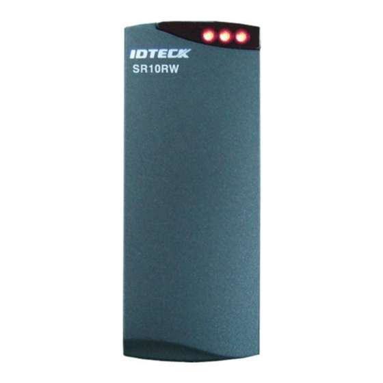
- Page 1 User’s Manual 13.56MHz [MIFARE] Contactless Smart Card Reader / Writer...
-
Page 2: Table Of Contents
Table of Contents 1. Important Safety Instructions ............3 2. General ................... 4 3. Features .................. 4 4. Specification ................5 5. Identifying Supplied Parts ............5 6. Installation ................6 7. Color Coded & Wiring Table ............8 8. Output Format ................9 9. -
Page 3: Important Safety Instructions
1. Important Safety Instructions The description below is to keep user’s safety and prevent any product damage. Please full y read these instructions and use the product properly. Danger: This symbol indicates that incorrect handling of the product may resu lt in serious injury or death. -
Page 4: General
The unit provides integrated operation of reader and writer and is designed by which can install easily to door frame or wall. The IDTECK SR10RW is elegant looking and built in an attractive 10cm (4") read range smart card reader. It also reads serial numbers from Philips Mifare™ Cards compatible, and can read and write special data of memory field internal card when operating of the unit is set by PRG2000RW. -
Page 5: Specification
1.8" X 4.5" X 0.88" (47mm X 115mm X 22mm) Weight 120g (0.26lb) Certification FCC, CE, KCC, RoHS 5. Identifying Supplied Parts Please unpack and check the contents of the box. Reader Module SR10RW Bezel User’s Manual Anchor Bolt 3.5*40 screw 3.5*25 screw Magnet (1ea) (1ea) -
Page 6: Installation
6. Installation 6-1. Mullion/Wall Mount: Drill 6-32 or M3 screws hole at 3.3" (8.38cm) intervals vertically And drill one 1/2" hole between previously drilled two holes for the reader cable 1.7" apart from the top hole. (If the gang box is already installed on the wall then skip this step.) 6-2. - Page 7 The typical read distance specification (2-4 inches at 12VDC) refers to operation without metal in the vicinity of the Reader. The read distance will be reduced if metal is installed nearby. The SR10RW generate a magnetic field on all sides of the Reader. Any metal that conducts electricity, especially metal that contains iron, steel or copper will interfere with the field and reduce the effective spacer between the Reader and the metal object.
-
Page 8: Color Coded & Wiring Table
eight inches (20cm) or less, a metal plate (for example: Reader isolation plate, metal wall) must be placed between the readers. To obtain the maximum read range, mount each proximity reader onto one or more Isolation Spacers. Two readers can simultaneously read the same badge or tag if the distance Note between the two readers is less than 8 inches (20cm), back-to-back. -
Page 9: Output Format
8. Output Format 8-1. 26/34bit Wiegand output format 1. Data format 26bit Wiegand output format 34bit Wiegand output format Bit 1 Even parity of bit 2 ~ bit 13 Bit 1 Even parity of bit 2 ~ bit 17 Bit 2∼9 Facility code (000 ~ 255) 4byte ID number Bit 2∼25... - Page 10 2. Data format (for PIN) Zero bit PIN (1char to 8char) low bit first, odd parity last Start Character (11010 Hex ‘B’) Zero bit (10bit) 3. Timing diagram (RD1) 1240us 940us Data (RD0) 6000us 6000us 1544us 8-3. RS-232 output format 1.
-
Page 11: Wire Connection To Access Controller
9. Wire Connection to Access Controller... -
Page 12: Operation
10-5. Tamper Switch If SR10RW is removed from the wall (or magnet) with the interval of more than 1cm, temper switch is operated, so 3 LED indicators turn on/off in order and buzzer keep sounding until no.7 of DIP switch is turned on. - Page 13 Software. The SR10RW supports RS232 or RS485 communication on the all field. Their communication is set by DIP switch. The SR10RW also supports 26/34bit Wiegand output format when it is set for access control. 10-8. 8 Channel DIP Switch Setting There is an 8 channel DIP switch and the switch is used to set Board ID, RS232/RS485, Temper output and Initialization.
-
Page 14: Troubleshooting
Board ID= 0 Board ID = 2+8 = 10 Board ID = 1+2+4+8+16 = 31 (Figure: Board ID Example) 11. Troubleshooting ※ If a problem occurs during the use of the product, do not attempt to disassemble the product by yourself. -
Page 15: Fcc Registration Information
Although same formatted card, specific character of card classified by manufacturing Cause company differs. (Reader of IDTECK is tuned by standard Phillips Mifare™ Card.) 1. Unique character of coil and manufacturing process by card manufacture company decide unique card character. So confirm using card to manufacture in same company. -
Page 16: Warranty Policy And Limitation Of Liability
IDTECK assumes. IDTECK IS NOT RESPONSIBLE FOR ANY PERSONAL INJURY, PROPERTY DAMAGE OR LOSS, DIRECT, SPECIAL, INCIDENTAL OR CONSEQUENTIAL DAMAGES, OR OTHER LOSS, AND IDTECK‟S... -
Page 17: How To Make Rma Request (After Sales Service)
14. How to Make RMA Request (After Sales Service) To make the RMA request, the product must be initially registered on IDTECK webpage. After registering the product, send it to IDTECK RMA Center. Please follow the instructions below: 1. Please register the RMA request via IDTECK webpage. - Page 18 The specifications contained in this manual are subject to change without notice at any time. 5F, Ace Techno Tower B/D, 684-1, Deungchon-Dong, Gangseo-Gu, Seoul, 157-030, Korea Tel : +82-2-2659-0055 Fax : +82-2-2659-0086 E-mail : webmaster@idteck.com Feb. 2011 Copyright © 2011 IDTECK Co., Ltd.
Need help?
Do you have a question about the SR10RW and is the answer not in the manual?
Questions and answers