Table of Contents
Advertisement
Quick Links
Advertisement
Table of Contents

Related Manuals for IDTECK SR10


Summary of Contents for IDTECK SR10
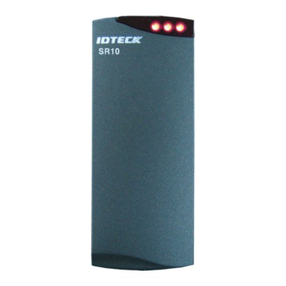
- Page 1 User’s Manual 13.56MHz Contactless Smart Card Reader...
-
Page 2: Table Of Contents
Table of Contents 1. Important Safety Instructions..............3 2. General ....................3 3. Features....................4 4. Identifying Supplied Parts ..............4 5. Specification ...................5 6. Installation....................6 7. Wire Color Table ..................8 8. Output Format..................9 9. Wire Connection to Access Controller ..........10 10. Operation.....................10 11. FCC Registration Information............12 12. -
Page 3: Important Safety Instructions
The IDTECK SR10 Smart Card Reader can be compatible with Philips Mifare™ Card. The unit provides integrated operation of reader and is designed by which can install easily to door frame or wall. The IDTECK SR10 is elegant looking and built in an attractive 10cm (4") read range smart card reader. -
Page 4: Features
- Compatible Software: Smart Card Read / Write Software - Compatible Controller: iCON100SR, iTDC-SR, Third Party Controller 4. Identifying Supplied Parts Please unpack and check the contents of the box: Reader Module SR10 Bezel User’s Manual (1ea) (1ea) (1copy) 3.5*40 Screw 3.5*12 Screw... -
Page 5: Specification
IP65 / IP66 Certification FCC, CE, MIC [Card reading range by Contactless Smart[Mifare] Reader Series] Model ISC80 ISK50 IMC135 IHC80 SR10 / SR30 / 4 inch (10cm) 2 inch (5cm) SRK101 SR10B / SR30B / 4 inch (10cm) 2 inch (5cm) -
Page 6: Installation
Moving the Reader away from the metal objects reduces energy loss. Try to limit the amount of metallic materials installed near the SR10. Use a plastic electrical box if possible. When installing the Reader on metal door frame, add Isolation Spacers between the Reader and metal door frame. - Page 7 ① Installation of two readers side by side and back to back Read range is not affected if the side by side distance between two readers is equal to or greater than eight inches (20cm). If the distance between the two readers is less than eight inches (20cm), field interference between the two readers may result in a double-badge read.
-
Page 8: Wire Color Table
7. Wire Color Table SIGNAL COLOR Main Power (+12V) Power Ground (GND) Black ABA Track II CP Out Orange Wiegand Data 0 Out / Green ABA Track II Data Out Wiegand Data 1 Out / White ABA Track II Clock Out Buzzer Control In Blue LED Control In... -
Page 9: Output Format
8. Output Format 8-1. 34/26bit Wiegand Output Format 1. Data format 26bit Wiegand output format 34bit Wiegand output format Bit 1 Even parity of bit 2 ~ bit 13 Bit 1 Even parity of bit 2 ~ bit 17 Bit 2∼9 Facility code (000 ~ 255) 4byte ID number Bit 2∼25... -
Page 10: Wire Connection To Access Controller
9. Wire Connection to Access Controller Access Controller Main Power (+12V) Black Power Ground (GND) Orange ABA Track II CP Out Wiegand Data 0 Out / Green ABA Track II Data Out Wiegand Data 1 Out / White ABA Track II Clock Out Blue Buzzer Control In Yellow... - Page 11 10-5. 4-byte (34bit) / 3-byte (26bit) selection: The reader outputs the serial number of a card which is a 4-byte number. It is possible to make the reader send only 3 bytes with the most significant byte trimmed off. It is useful when there are controllers which deal with 3-byte data only as most of existing controllers do.
-
Page 12: Fcc Registration Information
11. FCC Registration Information FCC REQUIREMENTS PART 15 Caution: Any changes or modifications in construction of this device which are not expressly approved by the manufacturer for compliance could void the user's authority to operate the equipment. NOTE: This device complies with Part 15 of the FCC Rules. Operation is subject to the following two conditions;... -
Page 13: Warranty And Service
370 Amapola Ave, #106 Torrance, CA 90501 Tel: 310-782-8383 Fax: 310-782-8298 E-mail: rflogics@rflogics.com Website: www.rflogics.com Hong Kong Branch: IDTECK Hong Kong 12/F, B2B Centre, No.36 Connaught Road West, Hong Kong Tel: 852-2581-9580 Fax: 852-2234-5150 E-mail: alchu@qala.com.hk Website: www.ristarhk.com Please use the original container, or pack the unit(s) in a sturdy carton with sufficient packing to prevent damage, include the following information: 1. - Page 14 MEMO...
- Page 15 MEMO...
- Page 16 The specification contained in this manual are subject to change without notice at any time. 5F, Ace Techno Tower B/D, 684-1, Deungchon-Dong, Gangseo-Gu, Seoul, 157-030, Korea Tel : +82-(2)-2659-0055 Fax : +82-(2)-2659-0086 E-mail : webmaster@idteck.com MARSR10HE2X July. 2006 Copyright ©2006 IDTECK Co., Ltd.
Need help?
Do you have a question about the SR10 and is the answer not in the manual?
Questions and answers