IDTECK Star RFK101 User Manual
Hide thumbs
Also See for Star RFK101:
- User manual (23 pages) ,
- Instruction (14 pages) ,
- Quick installation manual (8 pages)

Related Manuals for IDTECK Star RFK101


Summary of Contents for IDTECK Star RFK101
- Page 1 User’s Manual PIN & Proximity Card Reader...
-
Page 2: Table Of Contents
Table of Contents 1. Important Safety Instructions..................... 3 2. General ............................3 3. Features ............................. 4 4. Identifying Supplied Parts ......................4 5. Specification ..........................5 6. Installation ..........................6 7. Wire Color Table of the Reader ....................7 8. Wire Connection to Access Controller ..................8 9. -
Page 3: Important Safety Instructions
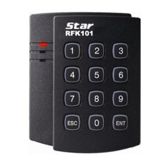
Keypad. The Star RFK101 has backlighting on the Keypad that ensures you successful operation even at night. The Star RFK101 allows you to access the door with proximity card and PIN numbers. Three LEDs of green, yellow and red colors and the built-in Piezo buzzer sound will guarantee you... -
Page 4: Features
3. Features - 125KHz Proximity & PIN Reader - PSK Modulation (IDTECK Format) - Read Range: Up to 4inch (10cm) - User format available - Output Format: » Card: 26bit Wiegand and RS232 (default) » Keypad: 8bit burst (default), 26bit Wiegand (selectable) or 4bit burst (selectable) -
Page 5: Specification
5. Specification Model RFK101 IDK50 / IMC125: Up to 2 inches (5cm) Passive Type Read Range IDC80 / IDC170: Up to 4 inches (10cm) Active Type IDA150 / IDA200 Compatible Reading Time (Card) 30ms Power / Current DC12V / Max.150mA 2 Ports for External LED Control, Default 1 Port for External Buzzer Control... -
Page 6: Installation
6. Installation 6-1. Use the provided Template on Page 18 to drill two 6-32 or M3 screw holes 3.3"(8.38cm) apart in vertical and one 1/2" hole at the center of these two holes. (If you have installed electric gang box then skip this step.) 6-2. -
Page 7: Wire Color Table Of The Reader
7. Wire Color Table of the Reader IO PINs Signal Wire Color 2PIN (J1) Main Power (+12V) DC +12V Power Ground Black 6PIN (J2) Wiegand Data 0 Out WIK_DATA0 Green Wiegand Data 1 Out WIK_DATA1 White Not Connect Not Connect Orange RS-232-TX TX OUT... -
Page 8: Wire Connection To Access Controller
8. Wire Connection to Access Controller Access Controller Main Power (+12V) Black Power Ground (GND) Green Wiegand Data 0 White Wiegand Data1 White with Green stripe Tamper Switch (NC) Gray Tamper Switch (COM) Blue Buzzer Control White with red stripe LED Control (Red) Yellow LED Control (Green) -
Page 9: Operation
9. Operation 9-1. Output Format Setting You can set output format of numeric input using output format setting switches. Select one between 4/8 bit Burst and 26bit Weigand format depending on the controller type receiving control input. Output format setting switches are on the back of RFK101 unit. Figure: Position of Output Format Setting Switch 9-2. - Page 10 9-3. Operation 9-3-1. Basic Operation 1. Once power is applied, you can hear 3 initial beeps while the 3 LEDs turn on. Then, the only red LED light stays on, indicating that the reader is in the standby mode after successful initialization and diagnostics.
- Page 11 5. LED Control: You may change the behavior of the red, green and yellow LEDs as follows; To keep the red LED turned off, connect the LED control in wire (white with red stripe) to the GND. To keep the green LED turned on, connect the LED control in wire (yellow wire) to the GND.
-
Page 12: Output Format
10. Output Format 10-1. 26bit Wiegand output format 1. Data format Bit 1 : Even parity of bit 2 - bit 13 Bit 2 – 9 : Facility code (000 - 255) Bit 10 – 25 : ID number (00000 - 65,535) Bit 26 : Odd parity of bit 14 - bit 25 2. - Page 13 (8bit Burst output format) Keypads Binary Hexa Keypads Binary Hexa 11110000 10010110 11100001 10000111 11010010 01111000 11000011 01101001 10110100 01011010 10100101 01001011 2. Timing diagram Data 1 3.5V 0.5V 100uS 100uS Data 0 3.5V 0.5V 100uS...
- Page 14 10-3. RS-232 output format 1. Data format (Baud rate: 9600bps) +15V Space (=0) Indeterminate Region Mark (=1) 8 Data Bits -15V 2 Stop Bits Start Bit Data packet corresponding to ASCII character 'A' 2. Data structure START(0X02H) DATA (8 Char) END (0x03H) (CARD output) START(0X02H)
-
Page 15: Fcc Registration Information
11. FCC Registration Information FCC Requirements Part 15 CAUTION: Any changes or modifications in construction of this device which are not expressly approved by the responsible for compliance could void the user's authority to operate the equipment. NOTE: This device complies with Part 15 of the FCC rules. Operation is subject to the following two conditions;... -
Page 16: Warranty Policy And Limitation Of Liability
4) to any losses, defects, or damages caused by lightning or other electrical discharge, natural disaster, misuse, accident or neglect. This Limited Warranty is in lieu of all other warranties, obligations, or liabilities on the part of IDTECK, and IDTECK DISCLAIMS ANY AND ALL WARRANTY, WHETHER EXPRESS OR IMPLIED, OF MERCHANTABILITY OR FITNESS FOR A PARTICULAR PURPOSE.IDTECK does not, and cannot,... -
Page 17: How To Make Rma Request (After Sales Service)
13. How to Make RMA Request (After Sales Service) To make the RMA request, the product must be initially registered on IDTECK webpage. Please attach the RMA request form on the product and send it to IDTECK RMA Center. Please follow the instructions below: 1. -
Page 18: Template
14. Template... - Page 19 The specifications contained in this manual are subject to be changed without notice at any time. 5F, Ace Techno Tower B/D, 684-1, Deungchon-Dong, Gangseo-Gu, Seoul, 157-030, Korea Tel : +82-2-2659-0055 Fax : +82-2-2659-0086 E-mail : webmaster@idteck.com Jan. 2010 Copyright © IDTECK Co., Ltd.
Need help?
Do you have a question about the Star RFK101 and is the answer not in the manual?
Questions and answers