Table of Contents
Advertisement
Quick Links
Download this manual
See also:
User Manual
Advertisement
Table of Contents

Subscribe to Our Youtube Channel
Related Manuals for IDTECK Star RFK505


Summary of Contents for IDTECK Star RFK505
- Page 1 User’s Manual PIN & Proximity Card Reader...
-
Page 2: Table Of Contents
Table of Contents 1. Important Safety Instructions ....................4 2. General..........................4 3. Features ..........................5 4. Specification........................6 5. Identifying Supplied Parts....................7 6. Product Overview........................7 6.1 Functions.........................7 6.2 Product Explanation ......................7 6.2.1 Front Panel Description...................7 6.2.2 Wire Color Table......................8 7. Installation Checkpoint & Tips...................9 7.1 Check Point before Installation ..................9 7.1.1 Selection of Cable ....................9 7.1.2 Recommended Cable Type and Permissible Length Cable ........9... - Page 3 10.2 HOW TO ENTER THE SETUP MENU ................17 11. Operation .........................17 11.1 NORMAL OPERATION....................17 11.2 DATA OUTPUT FORMAT (SETUP MENU F2).............17 11.2.1 WIEGAND OUTPUT FORMAT................17 11.2.2 ABA TRACK II MAGSTRIPE OUTPUT FORMAT ..........18 11.2.3 4/8bit BURST for PIN OUTPUT FORMAT ............19 12.
-
Page 4: Important Safety Instructions
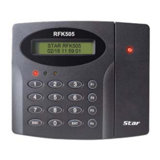
If the product exhibits a distinct change in performance. 2. General The Star RFK505 / iPASS IPK505 / IDTECK SRK505U is an elegant looking and built in an attractive 10cm (4”) read range PIN & Proximity Card Reader with keypad and LCD display. -
Page 5: Features
3. Features - 125KHz Proximity / PIN Reader - PSK Modulation - Read Range: Up to 4inch (10cm) - User format available - Network Communication via RS232 / RS422 / RS485 (Max.256ch) TCP/IP (External LAN Converter required) - 26bit Wiegand, ABA Track II and 4/8bit Burst for PIN Output Format selectable - 16 Numeric Keypads with Back Lighting - Current Time Display on the LCD - Dual Tamper Switches... -
Page 6: Specification
4. Specification Model RFK505 IDK50 / IMC125: Up to 2 inch (5cm) RFK505 IDC80 / IDC170: Up to 4 inch (10cm) IPK50: Up to 2 inch (5cm) Read Range IPK505 IPC80 / IPC170: Up to 4 inch (10cm) ISK50 / IHC80 / IMC135: Up to 2 inch (5cm) SRK505U SDC80: Up to 4 inch (10cm) Reading Time (Card) -
Page 7: Identifying Supplied Parts
LED control. Keypad If the Star RFK505 / iPASS IPK505 / IDTEKC SRK505U is not connected to a host PC, the integrated keypad and LCD display module can also be used for the entire programming process. -
Page 8: Wire Color Table
LCD Module: LCD module display Star RFK505 / iPASS IPK505 / IDTEKC SRK505U status. System Operation Status LED: When the power is applied to the unit, the red LED is turned on. During the reader transmits card data to the controller, the green LED is turned on and card reading status LED is flickers once changing the green color at the same time. -
Page 9: Installation Checkpoint & Tips
7. Installation Checkpoint & Tips Installing the Star RFK505 / iPASS IPK505 / IDTEKC SRK505U is an easy task. It can be installed with common hand tools and readily available communications wires. This section provides information about wiring, wire runs and other information to make the installation quick and easy. -
Page 10: Check Point During Installation
Sensor Input Belden #9514, 22 AWG 8 conductor, shielded Input Controller Door Lock, Alarm Device Belden #9409, 18AWG 300m ④ 2 conductor, unshielded Lock (Alarm) Controller RS232 Cable Belden #9829, 24 AWG ⑤ 2-twisted pair, shielded Converter Host P.C. RS485 Cable Controller Converter Controller... -
Page 11: How To Connect Termination Resistors
(GND of Star RFK505, iPASS IPK505, IDTECK SRK505U) Note that if the chassis ground is not properly connected to the earth and floated from the ground level, then grounding to the chassis ground will give the worst communication;... -
Page 12: Installation
RFK505 #1 RFK505 #2 RFK505 #N RFK505 #3 Figure : Grounding system 8. Installation 8.1 Installation of the Product 8.1.1. Use the provided template to drill two 6-32 holes and one 1/2" hole on the proper location of the wall to mount the Wall Mount bracket as shown below. (Skip this step if the gang box is already installed on the wall.) 8.2.2 Using 2 screws, install wall mount to the wall. -
Page 13: System Initialization
※ CAUTION Before mounting the main unit to the Wall Mount bracket, operational test of the unit should be completed, as the locking pins will lock the unit to the Wall Mount. Removing the unit from the Wall Mount bracket after they have been installed together may cause damages to the bracket and render its effectiveness. -
Page 14: Wire Connection To Access Controller
- Connect CP of the controller to ABA Track II CP Out (Orange wire). - If you disconnect power from the controller, connect the GND port between controllers. 8.4 Wire Connection to Access Controller Access Controller Main Power (+12V) Black Power Ground (GND) Orange ABA Track II CP Out... -
Page 15: Rs422 Connection (Multiple Rfk505S Connections)
Figure: RS422 Communication between RFK505 and Host PC 9.2.2 RS422 Connection (MULTIPLE RFK505s CONNECTIONS) RS422/RS232 converter is required to use RS422 communication between multiple RFK505s and a host computer. Please follow the following instructions. First, you have to connect all RS422 port of all RFK505s in parallel. - Connect RS422-TX(+) of one RFK505 to RS422-TX(+) of another RFK505. -
Page 16: Dial Up Modem
.3 DIAL UP MODEM Please, see the Software manual. .4 TCP/IP CONVERTER (EXTERNAL VERSION) Please, see the Software manual. 10. Basic Settings If you turn on the system power POWER ON after connected 3 wires (pink, cyan and black(GND)), you can enter system initialize mode. -
Page 17: How To Enter The Setup Menu
System Initialize Master Password System is Clear 1 – Yes, 0 - No [3141] Remove Wires!! 10.2 HOW TO ENTER THE SETUP MENU To setup or to change the RFK505 settings, the user has to enter the SETUP MENU first. To do so, press the 8 times <0> key for Master ID (Default setting “00000000”) and <ENT>... -
Page 18: Aba Track Ii Magstripe Output Format
2. Timing diagram Data 1 3.5V 0.5V 40uS 40uS Data 0 3.5V 0.5V 40uS 11.2.2 ABA TRACK II MAGSTRIPE OUTPUT FORMAT 1. Data format (for Card numbers) Zero bit ID number (00000~65535) Facility Code (1248P (00000~00255)) low bit first, odd parity last Start Character (11010 Hex ‘B’) Zero bit (10bit) -
Page 19: 4/8Bit Burst For Pin Output Format
3. Timing diagram (RD1) 1240us 940us Data (RD0) 6000us 6000us 1544us 11.2.3 4/8bit BURST for PIN OUTPUT FORMAT 1. Data format (4bit Burst output format) Keypads Binary Hexa Keypads Binary Hexa 0000 0110 0001 0111 0010 1000 0011 1001 0100 1010 0101 1011... -
Page 20: Setting Changes
2. Timing diagram Data 1 3.5V 0.5V 40uS 40uS Data 0 3.5V 0.5V 40uS 12. Setting Changes INITIAL DISPLAY (MODEL NAME, CURRENT TIME) ID INPUT? MASTER ID /PW/FINGERPRINT ? OPERATE GENERAL MODE SETUP MODE SETUP F1 MODE SETUP F2 MODE SETUP F3 MODE SETUP F4 MODE 1. -
Page 21: Setup Menu F1
the user can scroll up and down the SUB MENU by pressing <4> and <6> key in the main SETUP MENU. If the user pressed <ESC> key, RFK505 / IPK505 will be out of the SETUP MENU and returned to normal operation. The Master ID for SRK505U is 10 times <0> key (Default setting). The RFK505 / IPK505 / SRK505 is not used SETUP MENU F3. -
Page 22: Communication Id (Address) Display
12.1.2 COMMUNICATION ID (ADDRESS) DISPLAY ☞. This is communication ID setting menu. COMM ID SETTING To change the communication ID, press <ENT> key. ☞. The number on the LCD is the current communication ID COMM ADDRESS (Device No.) Please press <ENT> key again to set a new communication ID. -
Page 23: System Initialize
☞. The RFK505 is waiting for a keypad that is to be register- INPUT NEW MASTER [█_______] RFK505 / IPK505: 4 or 8 digits SRK505 : 10 digits (“0000000001” ~ “4294967295”) ☞. Enter a new Master password (four digits) and finish Enter Password changing Master ID █___... -
Page 24: Setup Menu F2
12.2 SETUP MENU F2 STATUS LCD DISPLAY <4> or <6> key CARD NO. OUTPUT MODE WIEGAND <4> or <6> key <4> or <6> key ABA TRACK II LED_BUZZER_CON GLXX YLXX BZXX <4> or <6> key FUNC_KEY OUT 4BIT BURST 8BIT BURST 12.2.1 LCD DISPLAY SETTING ☞. -
Page 25: Led_Buzzer_Control
• 8BIT BURST: OUTPUT MODE When pressing the keypad, the unit is outputted to ABA TRACK 8bit burst. • ABA TRACK: Outputs ID data through ABA track output line. (Open collector) 12.2.3 LED_BUZZER_CONTROL ☞. This function controls LED and Buzzer of the reader. LED_BUZZER_CON GL (Green LED): It controls about card reading status. -
Page 26: Lcd Test
12.3.2 LCD TEST ☞. To test the performance of LCD, press <ENT> key. LCD TEST As the test proceeds, several characters will move quickly from right to left. If character of each field on the LCD is not, its LCD has a problem. Last Update After completing LCD test, it displays updated day. -
Page 27: Troubleshooting
13. Troubleshooting ☞ Broken or abnormal letters show on the LCD, when powered on. Cause Of troubles of circuits near around 1. Initialize the controller referring “hardware initialization of the manual” 2. Set the current time in Set-Up menu of F1 and turn its power off and on Solution again. - Page 28 3. In case of setting RS422 communication, recommend to use line-end resistors of 120 Ohm between the RX(+) and RX(-) lines and between the TX(+) and TX(-) lines, and apply the same resistors to the converter RS422 lines. Consult a service center or an electric technician if you cannot be sure how to do it. 4.
-
Page 29: Fcc Registration Information
14. FCC Registration Information FCC REQUIREMENTS PART 15 Caution: Any changes or modifications in construction of this device which are not expressly approved by the manufacturer for compliance could void the user's authority to operate the equipment. NOTE: This device complies with Part 15 of the FCC Rules. Operation is subject to the following two conditions;... -
Page 30: Warranty And Service
370 Amapola Ave, #106 Torrance, CA 90501 Tel: 310-782-8383 Fax: 310-782-8298 E-mail: rflogics@rflogics.com Website: www.rflogics.com Hong Kong Branch: IDTECK Hong Kong 12/F, B2B Centre, No.36 Connaught Road West, Hong Kong Tel: 852-2581-9580 Fax: 852-2234-5150 E-mail: alchu@qala.com.hk Website: www.ristarhk.com Please use the original container, or pack the unit(s) in a sturdy carton with sufficient packing to prevent damage and include the following information: 1. -
Page 31: Template
16. Template... - Page 32 The specifications contained in this manual are subject to change without notice at any time. 5F, Ace Techno Tower B/D, 684-1, Deungchon-Dong, Gangseo-Gu, Seoul, 157-030, Korea Tel : +82-2-2659-0055 Fax : +82-2-2659-0086 E-mail : webmaster@idteck.com MARK505HE1X December. 2007 Copyright ©2007 IDTECK Co., Ltd.
Need help?
Do you have a question about the Star RFK505 and is the answer not in the manual?
Questions and answers