Subscribe to Our Youtube Channel
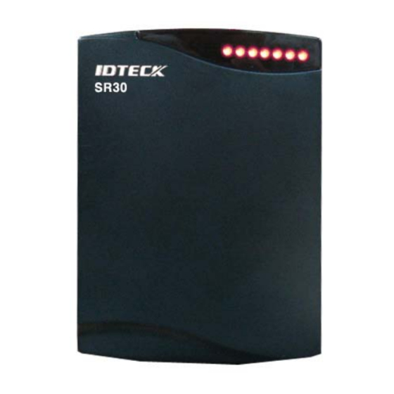
Summary of Contents for IDTECK SR30
- Page 1 User’s Manual 13.56MHz Contactless Smart Card Reader 13.56MHz Contactless Universal Smart Card Reader Fingerprint-Stored Smart Card ID-Only Reader...
-
Page 2: Table Of Contents
Table of Contents 1. Important Safety Instructions ..............3 2. General......................4 3. Features ......................4 4. Identifying Supplied Parts.................5 5. Specification....................6 6. Installation ....................8 7. Wire Color Table..................9 8. Output Format ..................10 9. Wire Connection to Access Controller...........11 11. Appendix ....................12 12. FCC Registration Information ...............13 13. -
Page 3: Important Safety Instructions
1. Important Safety Instructions When using the 13.56MHz [MIFARE] Contactless Smart Card Reader (SR30) / 13.56MHz Contactless Universal Smart Card Reader (SR30U) / Fingerprint Stored Smart Card ID Only Reader (SR30B), basic safety precautions should always be followed to reduce the risk of fire, electrical shock, and injury to persons. -
Page 4: General
The IDTECK SR30/SR30U/SR30B Smart Card Reader is a proximity reader with the read range of up to 4 inches (10cm) and can be installed on any doorframe or mounted on any wall. IDTECK SR30 reads the serial number stored on the Philips Mifare™ card (ISO14443 Type A) and transmits the data in various formats. -
Page 5: Identifying Supplied Parts
- Compatible Controller: iCON100, iTDC, FINGER007SRB, Third Party Controller. - Compatible Reader: SR10B, SRK101B, FGR006SRB, FINGER006SRB 4. Identifying Supplied Parts Please unpack and check the contents of the box: Reader Module SR30/SR30U/SR30B Bezel User Manual (1ea) (1ea) (1 copy) 3.5*40 screw 3.5*25 screw... -
Page 6: Specification
5. Specification Model SR30 SR30U SR30B ISK50 / IMC135: Up to 2 inches (5cm) Type A ISC80: Up to 4 inches (10cm) Read Range ISC80B: Up to 2 Type B inches (5cm) Card Reading Time 30ms Power / Current DC 12V / Max. 150mA... - Page 7 Card Read Range of each Contactless Smart[Mifare] Reader Model ISC80 ISC80B ISK50 IMC135 IHC80 SR10 / Up to 4 SR30 / inches Up to 2 inches (5cm) SRK101 (10cm) SR10B / Up to 4 SR30B / inches Up to 2 inches (5cm)
-
Page 8: Installation
6. Installation 6-1. Drilling Screw Holes Drill two 6-32 or M3 screw holes 3.3" (8.38cm) apart vertically, and drill one 1/2" hole for the reader cable between the two holes (see the diagram below). 6-2. Installing the Reader Module Put the reader cable into the center hole and hold the reader module using two 6-32 or M3 screws. 6-3. -
Page 9: Wire Color Table
Wiegand Data 1 Out / White ABA Track II Clock Out Buzzer Control In Blue LED Control In Yellow †34/26bit Wiegand Select In Gray RS232 (TX) Purple RS232 (RX) Brown * Cut out the tail connector before installation. †Applicable to SR30 only. -
Page 10: Output Format
8. Output Format 8-1. Wiegand Output Format Data Format (34-bit /26-bit) Bit 1 / Bit 1 : Even Parity Bit of Bit 2 to Bit 17 / Bit 2 to Bit 13 Bit 2 to Bit 33 / Bit 2 to Bit 25 : 4-byte ID number / 3-byte ID number Bit 34 / Bit 26 : Odd Parity Bit of Bit 18 to Bit 33 / Bit 14 to Bit 25 Timing Diagram 8-2 RS-232C(Option) Data Format... -
Page 11: Wire Connection To Access Controller
9. Wire Connection to Access Controller Make sure the wire connections are correctly done. † SR30 only 10. Operation 10-1. After the reader is powered on and becomes ready, the red LED will be lit. 10-2. Bring a card close to the reader until the green LED is lit and the buzzer beeps. Then, the reader transmits the RF card data to the controller and changes the LED color to red for next reading. -
Page 12: Appendix
10-5. 4-byte(34bit) / 3-byte(26bit) Select In (SR30 Only) The reader transmits the serial number of a card which is a 4-byte number. It is possible to set the reader to transmit only 3 bytes with the first one byte removed. It is useful when the connected controller supports 3-byte data only. -
Page 13: Fcc Registration Information
Cause companies and, therefore, have different characteristics. (IDTECK cards are made according to the MIFARE card of Philips. 1. Depending on the card manufacturer and special manufacturing processes, the characteristics of the card may vary. Therefore, make sure if the cards are manufactured by one company. -
Page 14: Warranty Policy And Limitation Of Liability
4) to any losses, defects, or damages caused by lightning or other electrical discharge, natural disaster, misuse, accident or neglect. This Limited Warranty is in lieu of all other warranties, obligations, or liabilities on the part of IDTECK, and IDTECK DISCLAIMS ANY AND ALL WARRANTY, WHETHER EXPRESS OR IMPLIED, OF MERCHANTABILITY OR FITNESS FOR A PARTICULAR PURPOSE.IDTECK does not, and cannot,... - Page 15 RMA REQUEST FORM IDTECK accepts only on-line RMA requests on our Website (www.idteck.com). Please provide us with basic information in the below form so that we can understand your problems better. Send us back this form with your products after an RMA code is issued on our Website. This form is not compulsory.
- Page 16 The specifications contained in this manual are subject to change without notice at any time. 5F, Ace Techno Tower B/D, 684-1, Deungchon-Dong, Gangseo-Gu, Seoul, 157-030, Korea Tel : +82-(2)-2659-0055 Fax : +82-(2)-2659-0086 E-mail : webmaster@idteck.com MARSR30HK3X Feb 2008 Copyright ©2008 IDTECK Co., Ltd. MARSR3UHK1X MARSR3BHK3X...


Need help?
Do you have a question about the SR30 and is the answer not in the manual?
Questions and answers