Sirona Orthophos XG 3 Installation Instructions Manual
Hide thumbs
Also See for Orthophos XG 3:
- Operating instructions manual (76 pages) ,
- Maintenance manual (30 pages) ,
- Service manual (630 pages)

Related Manuals for Sirona Orthophos XG 3


Summary of Contents for Sirona Orthophos XG 3
- Page 1 NMKOMNR kÉï=~ë=çÑW= loqelmelp=ud=P= fåëí~ää~íáçå=fåëíêìÅíáçåë båÖäáëÜ Prog.
-
Page 2: General Information
Sirona Dental Systems GmbH Installation Instructions ORTHOPHOS XG 3 General information For installation, please refer also to the following docu - About this document ments: This document describes the installation of the ORTHO - • Installation drawings PHOS XG XG3 panoramic X-ray unit. -
Page 3: Table Of Contents
Sirona Dental Systems GmbH Installation Instructions ORTHOPHOS XG 3 Contents Before you begin ....................... 5 Identification of warnings ................. 6 Safety....................... 7 System and sensor versions..............8 Dimensions/Space requirements............. 9 Mounting options ................... 10 Installation versions ................11 Delivery and transport ....................13 Delivery.................... - Page 4 Sirona Dental Systems GmbH Installation Instructions ORTHOPHOS XG 3 Startup for USA/Canada only ..................73 Startup, measurements and controls ............. 74 Power supply adequacy ................. 75 Tube Current Verification ............... 76 kV – verification / Exposure Time Verification........79 Checking the laser for USA/Canada only..........81 Checking the system adjustment ..................
-
Page 5: Before You Begin
Before you begin ORTHOPHOS XG 3 60 51 416 D 3352 D 3352.031.03.18.02... -
Page 6: Identification Of Warnings
The structure, appearance and use of warning and safety information in Sirona documents are based on the ANSI Z535 standard. The following warnings may be used in this document:... -
Page 7: Safety
If any equipment not approved by SIRONA is connect - ed, it must comply with the applicable standards: - IEC 60950-1 for information technology equipment - IEC 60 601-1 for medical electrical equipment. -
Page 8: System And Sensor Versions
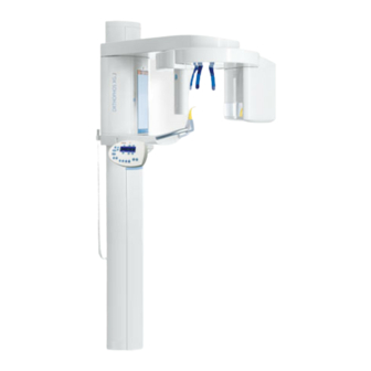
1 Before you begin Sirona Dental Systems GmbH 1.3 System and sensor versions Installation Instructions ORTHOPHOS XG 3 1.3 System and sensor versions 1. ORTHOPHOS XG 3 Digital unit 2. XG PAN sensor Sensor for panoramic (PAN) X-ray 60 51 416 D 3352... -
Page 9: Dimensions/Space Requirements
Sirona Dental Systems GmbH 1 Before you begin Installation Instructions ORTHOPHOS XG 3 1.4 Dimensions/Space requirements 1.4 Dimensions/Space requirements NOTICE NOTICE The minimum ceiling height should be 2.10 m (82 11/16"). If The dimensions specified here apply to installation of the the ceiling height is lower than 2.27 m (89 3/8“) (max. -
Page 10: Mounting Options
If the unit is installed freely with a floor stand, the quality of (see Section 3.3) the resulting X-ray exposures may be impaired, depending on the floor or surface conditions. Sirona there - 2. Wall-mounted installation with 2 wall holders (and fore recommends additional fastening of the unit with an up - no floor fastening) if only wall installation is possible per wall holder also when installing it with a floor stand. -
Page 11: Installation Versions
1.6 Installation versions Standard installation: Installation version 1 (see section 5.3.1): ORTHOPHOS XG 3 without remote control with re - ORTHOPHOS XG 3 with remote control outside the X-ray room without release button on the coiled ca - lease button on the coiled cable in the treatment room. - Page 12 1 Before you begin Sirona Dental Systems GmbH 1.6 Installation versions Installation Instructions ORTHOPHOS XG 3 60 51 416 D 3352 D 3352.031.03.18.02...
-
Page 13: Delivery And Transport
Delivery and transport ORTHOPHOS XG 3 60 51 416 D 3352 D 3352.031.03.18.02... -
Page 14: Delivery
Please leave the styrofoam packaging and transport pallet attached to the unit. All SIRONA equipment is carefully checked and packed prior to shipment. Please carry out an incoming inspection Save one of the lateral styrofoam packaging parts for of the equipment in order to make sure that it was not dam - later use as an installation aid A. - Page 15 Make a note on the delivery slip that the indicator is acti - vated. Have this confirmed on the delivery note by the driver of the transport company. Fax the delivery slip to the Sirona Customer Service Center (CSC). Enter the state of the indicators in the startup report in the case of warranty claims.
- Page 16 2 Delivery and transport Sirona Dental Systems GmbH 2.1 Delivery Installation Instructions ORTHOPHOS XG 3 Bite block Bite block fixation Chin pad Chin rest Accessories: Panoramic X-ray unit 1. Forehead (1x) and temple supports (2x) Contact segment standard yellow (1x) 2.
- Page 17 Sirona Dental Systems GmbH 2 Delivery and transport Installation Instructions ORTHOPHOS XG 3 2.1 Delivery Bottom side Top side Hygienic protection Adjustment set: Panoramic X-ray unit Hygienic protective sleeves for... 14. Panoramic needle phantom Forehead and temple supports (500x) 15. Set of Torx offset screwdrivers 10.
-
Page 18: Transport To The Installation Site
If possible leave the packaging attached to the unit during The center styrofoam part should remain attached to the unit for protection. If this is not possible, SIRONA recom - transport in order to protect it against damage. mends securing the tube assembly in its position with the supplied strap prior to any further transport 1. -
Page 19: Installation: Panoramic X-Ray Unit
Installation: Panoramic X-ray unit ORTHOPHOS XG 3 60 51 416 D 3352 D 3352.031.03.18.02... -
Page 20: Installation Material
3 Installation: Panoramic X-ray unit Sirona Dental Systems GmbH 3.1 Installation material Installation Instructions ORTHOPHOS XG 3 3.1 Installation material for installation on wooden stud for installation frame on wooden stud frame Standard version Option 1: with second wall holder (see Section 3.3) - Page 21 Sirona Dental Systems GmbH 3 Installation: Panoramic X-ray unit Installation Instructions ORTHOPHOS XG 3 3.1 Installation material Option 2 Mounting hardware Floor stand Covers Cover Floor stand Slide Option 2: Floor stand installation – Nut M8: 2 pc. (see Section 3.4) –...
-
Page 22: Required Tools
3 Installation: Panoramic X-ray unit Sirona Dental Systems GmbH 3.2 Required tools Installation Instructions ORTHOPHOS XG 3 3.2 Required tools 1. Masonry drill Required measuring instruments – Δια.10mm (3/8“) • Multimeter or ammeter (battery-operated) 2. Impact drill or percussion drill •... -
Page 23: Wall Mounting (Standard/Option 1)
Sirona Dental Systems GmbH 3 Installation: Panoramic X-ray unit Installation Instructions ORTHOPHOS XG 3 3.3 Wall mounting (standard/option 1) 3.3 Wall mounting (standard/option 1) 60 51 416 D 3352 D 3352.031.03.18.02... - Page 24 3 Installation: Panoramic X-ray unit Sirona Dental Systems GmbH 3.3 Wall mounting (standard/option 1) Installation Instructions ORTHOPHOS XG 3 • Remove profile cover A. 1. Position the two installation aids B at the foot C of the device and secure their position with adhesive tape.
- Page 25 Sirona Dental Systems GmbH 3 Installation: Panoramic X-ray unit Installation Instructions ORTHOPHOS XG 3 3.3 Wall mounting (standard/option 1) Mount the upper wall holder. CAUTION If the setup site for the unit is carpeted, the carpeting must be removed. Wall plugs! Each wall plug must withstand an extraction force of 700 N.
- Page 26 3 Installation: Panoramic X-ray unit Sirona Dental Systems GmbH 3.3 Wall mounting (standard/option 1) Installation Instructions ORTHOPHOS XG 3 Only with second wall holder (option 1): 5. Mount the lower wall holder. Δια. 10 mm Δια. 3/8″ 60 51 416 D 3352...
- Page 27 Hold the unit laterally at the styrofoam packaging to do this. NOTICE SIRONA recommends leaving the styrofoam packaging on the unit during the entire installation procedure! If due to on-site conditions it is unavoidable to remove the...
- Page 28 3 Installation: Panoramic X-ray unit Sirona Dental Systems GmbH 3.3 Wall mounting (standard/option 1) Installation Instructions ORTHOPHOS XG 3 ➋ ➊ 9. Remove the transport safety device (A) prior to unit 12. Level the unit by moving the unit base in both directions startup.
- Page 29 Sirona Dental Systems GmbH 3 Installation: Panoramic X-ray unit Installation Instructions ORTHOPHOS XG 3 3.3 Wall mounting (standard/option 1) Δια. 10 mm 2x S 10 2x δια. 8.4 2x 8x80 13. Drill through the recesses of the stand into the floor. In - sert wall plug M, and check again that the stand is aligned correctly (see step 10).
-
Page 30: Installing The Floor Stand (Option 2)
3 Installation: Panoramic X-ray unit Sirona Dental Systems GmbH 3.4 Installing the floor stand (option 2) Installation Instructions ORTHOPHOS XG 3 3.4 Installing the floor stand (option 2) Must be dis - mantled ly - ing on its CAUTION IMPORTANT... - Page 31 Sirona Dental Systems GmbH 3 Installation: Panoramic X-ray unit Installation Instructions ORTHOPHOS XG 3 3.4 Installing the floor stand (option 2) Carefully push the unit toward the base just far enough so that the center styrofoam part nudges lower supporting block H.
- Page 32 3 Installation: Panoramic X-ray unit Sirona Dental Systems GmbH 3.4 Installing the floor stand (option 2) Installation Instructions ORTHOPHOS XG 3 4x M 10x25 δια. 4x δια. 10.5 2x M8 2x EM 8 x 60 2x M 8x80 7. Screw adjustment plate (K) onto the stand firmly.
- Page 33 Sirona Dental Systems GmbH 3 Installation: Panoramic X-ray unit Installation Instructions ORTHOPHOS XG 3 3.4 Installing the floor stand (option 2) 3x M 10 3x δια. 10.5 Position the base plate with the threaded bolts (includ - ing the mounted support) on the adjustment plate and attach the base plate loosely with the 3 adjustment nuts Q (and washers).
- Page 34 3 Installation: Panoramic X-ray unit Sirona Dental Systems GmbH 3.4 Installing the floor stand (option 2) Installation Instructions ORTHOPHOS XG 3 10. + 11. 1x δια. 10.5 1x M 10x50 1x M 10 Profile clamp 10. Insert screw R through washer S and then through the •...
- Page 35 Sirona Dental Systems GmbH 3 Installation: Panoramic X-ray unit Installation Instructions ORTHOPHOS XG 3 3.4 Installing the floor stand (option 2) • Set up the unit including the center styrofoam part. IMPORTANT Please observe the required movement range of the X-ray unit during installation (see section 1.6).
- Page 36 3 Installation: Panoramic X-ray unit Sirona Dental Systems GmbH 3.4 Installing the floor stand (option 2) Installation Instructions ORTHOPHOS XG 3 ➋ ➊ • Loosen screw R and adjusting nuts Q again slightly. IMPORTANT 13. Level the unit in both directions by turning adjusting Be sure to tighten all adjusting nuts equally (to the same nuts Q while measuring with the spirit level.
- Page 37 Sirona Dental Systems GmbH 3 Installation: Panoramic X-ray unit Installation Instructions ORTHOPHOS XG 3 3.4 Installing the floor stand (option 2) 15. Mount the upper wall holder. CAUTION In case of mounting on weight-bearing wood struc - tures: Use the enclosed wood screws and washers from the mounting kit for mounting the unit on weight-bearing wood structures.
- Page 38 3 Installation: Panoramic X-ray unit Sirona Dental Systems GmbH 3.4 Installing the floor stand (option 2) Installation Instructions ORTHOPHOS XG 3 2x M8 2x δια. 8.4 2x M8x30 • Slide the unit with the assembled floor stand up to the wall.
- Page 39 Sirona Dental Systems GmbH 3 Installation: Panoramic X-ray unit Installation Instructions ORTHOPHOS XG 3 3.4 Installing the floor stand (option 2) Δια. 12 mm Δια. 1/2″ 5x S12 5x 10 x 160 • Level the unit again in both directions with the help of 17.
-
Page 40: Removing The Transport Safety Device
3 Installation: Panoramic X-ray unit Sirona Dental Systems GmbH 3.5 Removing the transport safety device Installation Instructions ORTHOPHOS XG 3 3.5 Removing the transport safety device 1. Remove the transport safety devices B prior to unit startup. IMPORTANT Keep transport safety devices B in a safe place. You will need them should the unit be moved again. -
Page 41: Installing The Release Button Holder
Sirona Dental Systems GmbH 3 Installation: Panoramic X-ray unit Installation Instructions ORTHOPHOS XG 3 3.6 Installing the release button holder 3.6 Installing the release button holder IMPORTANT Only install the holder to the unit if you do not intend to use... -
Page 42: Attaching The Covers
3 Installation: Panoramic X-ray unit Sirona Dental Systems GmbH 3.7 Attaching the covers Installation Instructions ORTHOPHOS XG 3 3.7 Attaching the covers Use the 4 screws A to refasten the assembled housing IMPORTANT cover to the unit. These covers must be attached only if the unit is installed with the floor stand and does not stand against a wall. - Page 43 Sirona Dental Systems GmbH 3 Installation: Panoramic X-ray unit Installation Instructions ORTHOPHOS XG 3 3.7 Attaching the covers Attach all remaining unit housing covers. IMPORTANT In order to attach the floor stand covers properly, the four spring clamps E must be placed on the base plate in such a way that the two covers F and G remain assembled after they are attached (see detail drawing above).
- Page 44 3 Installation: Panoramic X-ray unit Sirona Dental Systems GmbH 3.7 Attaching the covers Installation Instructions ORTHOPHOS XG 3 60 51 416 D 3352 D 3352.031.03.18.02...
-
Page 45: Electrical Connection
Electrical connection ORTHOPHOS XG 3 60 51 416 D 3352 D 3352.031.03.18.02... -
Page 46: Connecting The Control Cables (Pan)
4 Electrical connection Sirona Dental Systems GmbH 4.1 Connecting the control cables (PAN) Installation Instructions ORTHOPHOS XG 3 4.1 Connecting the control cables (PAN) L117 Duplex patch cable, 1:1 connection, SC/SC 50/125 μm X108 X101 L117 Coiled cable Media convert - Switch* Cat.5... -
Page 47: Connecting The Line Voltage
Sirona Dental Systems GmbH 4 Electrical connection Installation Instructions ORTHOPHOS XG 3 4.2 Connecting the line voltage 4.2 Connecting the line voltage DANGER WARNING Fixed connection! Be sure to connect the second protective ground wire The installation of a power plug instead of the pre - to ground. - Page 48 4 Electrical connection Sirona Dental Systems GmbH 4.2 Connecting the line voltage Installation Instructions ORTHOPHOS XG 3 Media converter WARNING When operating the unit at exhibitions and fairs, you must observe the information provided in section 11.3 Demo mode! Plug the connector of the media converter's power sup - •...
-
Page 49: Installation: Remote Control
Installation: Remote control ORTHOPHOS XG 3 60 51 416 D 3352 D 3352.031.03.18.02... -
Page 50: Installation Material/Tools
5 Installation: Remote control Sirona Dental Systems GmbH 5.1 Installation material/tools Installation Instructions ORTHOPHOS XG 3 5.1 Installation material/tools 1. Installation material for remote control Required tools – Masonry drill δια.6 mm (1/4“) – Wood screw 4x30 (3/16x1 1/4): 3 pc. -
Page 51: Mechanical Installation
Sirona Dental Systems GmbH 5 Installation: Remote control Installation Instructions ORTHOPHOS XG 3 5.2 Mechanical installation 5.2 Mechanical installation Δια. 6mm 3x S 6 3x 4x30 Carefully press the blade screwdriver in groove A from IMPORTANT below (do not pry!) and remove the chassis to the rear. - Page 52 5 Installation: Remote control Sirona Dental Systems GmbH 5.2 Mechanical installation Installation Instructions ORTHOPHOS XG 3 10 mm 3x 4x30 3/8“ L117 Cable shield a p p r o x . 60 mm 250 mm 2 3/8“ from wall exit...
-
Page 53: Connecting The Control Cables (Remote)
Sirona Dental Systems GmbH 5 Installation: Remote control Installation Instructions ORTHOPHOS XG 3 5.3 Connecting the control cables (REMOTE) 5.3 Connecting the control cables (REMOTE) 15 m 590“ X108 (Shorten if necessary) L 117 DX42 X 108 5.3.1 Installation version 1: without release button and coiled cable Attach cable L117 at shield clamp A. - Page 54 5 Installation: Remote control Sirona Dental Systems GmbH 5.3 Connecting the control cables (REMOTE) Installation Instructions ORTHOPHOS XG 3 X101 5.3.2 Installation version 2: with release button and coiled cable Using the two screws D, fasten the release button hold - NOTICE er B to the keyboard.
- Page 55 Sirona Dental Systems GmbH 5 Installation: Remote control Installation Instructions ORTHOPHOS XG 3 5.3 Connecting the control cables (REMOTE) Connecting the control cable • Connect control cable L117 as described in section 5.3 on page 53. 60 51 416 D 3352...
-
Page 56: Connecting The Door Contact Switch
5 Installation: Remote control Sirona Dental Systems GmbH 5.4 Connecting the door contact switch Installation Instructions ORTHOPHOS XG 3 5.4 Connecting the door contact switch X108 Door contact switch DX42 X 108 1. Connect the door contact switch between terminal X 108 pin 1 (board DX 42) and control cable L117 pin 1 (WHGN). -
Page 57: Connecting The X-Ray Warning Lamp
Sirona Dental Systems GmbH 5 Installation: Remote control Installation Instructions ORTHOPHOS XG 3 5.5 Connecting the X-ray warning lamp 5.5 Connecting the X-ray warning lamp L117 X105 DX42 It is possible to activate an X-ray warning lamp via the Insert cable A for connection of the X-ray warning lamp remote control. -
Page 58: Final Work
5 Installation: Remote control Sirona Dental Systems GmbH 5.6 Final work Installation Instructions ORTHOPHOS XG 3 5.6 Final work DHHS label WARNING 1. Reassemble the remote control and place the release button (if installed) in the holder. NOTICE Make sure that no cables are pulled off when you clip the cover on. -
Page 59: Safety Checks
Safety checks ORTHOPHOS XG 3 60 51 416 D 3352 D 3352.031.03.18.02... -
Page 60: Checking The Protective Ground Wires
6 Safety checks Sirona Dental Systems GmbH 6.1 Checking the protective ground wires Installation Instructions ORTHOPHOS XG 3 6.1 Checking the protective ground wires Measuring point Central ground wire Ammeter Power source Measuring setup for protective Voltmeter ground wire test... - Page 61 Sirona Dental Systems GmbH 6 Safety checks Installation Instructions ORTHOPHOS XG 3 6.1 Checking the protective ground wires Measuring point A: Central ground wire Power cable ORTHOPHOS XG Second protective ground wire Measuring points B and C: GNYE power connection and 2nd ground 60 51 416 D 3352 D 3352.031.03.18.02...
- Page 62 6 Safety checks Sirona Dental Systems GmbH 6.1 Checking the protective ground wires Installation Instructions ORTHOPHOS XG 3 Board cage DX32 X-ray tube assembly Measuring points D and E: IMPORTANT If the resistance exceeds the value specified in the table,...
-
Page 63: Checking The Device Leakage Current
Sirona Dental Systems GmbH 6 Safety checks Installation Instructions ORTHOPHOS XG 3 6.2 Checking the device leakage current 6.2 Checking the device leakage current IMPORTANT DANGER According to Note 2 below Table 2 of standard IEC 62353, Perilous shock hazard! - Page 64 6 Safety checks Sirona Dental Systems GmbH 6.2 Checking the device leakage current Installation Instructions ORTHOPHOS XG 3 60 51 416 D 3352 D 3352.031.03.18.02...
-
Page 65: Initial Startup
Initial startup ORTHOPHOS XG 3 60 51 416 D 3352 D 3352.031.03.18.02... -
Page 66: Inserting The Forehead And Temple Supports
7 Initial startup Sirona Dental Systems GmbH 7.1 Inserting the forehead and temple supports Installation Instructions ORTHOPHOS XG 3 7.1 Inserting the forehead and temple supports 1. Insert the forehead and temple supports until they lock in place. 60 51 416 D 3352... -
Page 67: Inserting The Sensor
Sirona Dental Systems GmbH 7 Initial startup Installation Instructions ORTHOPHOS XG 3 7.2 Inserting the sensor 7.2 Inserting the sensor NOTICE The sensor is a sensitive component, and therefore must be handled with special care. Carefully plug sensor A upward into the holder until it audibly locks in place. -
Page 68: Switching The Units On
7 Initial startup Sirona Dental Systems GmbH 7.3 Switching the units ON Installation Instructions ORTHOPHOS XG 3 7.3 Switching the units ON Switch the unit ON. WARNING – All LEDs and the LED display on the Multipad light When performing the following test, be sure to observe up briefly. -
Page 69: Checking The Data Paths
Sirona Dental Systems GmbH 7 Initial startup Installation Instructions ORTHOPHOS XG 3 7.4 Checking the data paths 7.4 Checking the data paths 7.4.1 Generating pan/ceph test images/Checking the pan/ceph/PC data path In SIDEXIS XG, select the constancy test: IMPORTANT UTILITIES CONSTANCY TEST . - Page 70 7 Initial startup Sirona Dental Systems GmbH 7.4 Checking the data paths Installation Instructions ORTHOPHOS XG 3 Select/confirm the X-ray device: IMPORTANT Select e.g. ROOM and click OK . During operation in the service mode, the unit switches from the user mode to the PC service mode logged by the PC.
- Page 71 Sirona Dental Systems GmbH 7 Initial startup Installation Instructions ORTHOPHOS XG 3 7.4 Checking the data paths Prog. 6. Take an exposure: Test pattern for panoramic unit – Press the R key on the Multipad to move the unit back to the starting position.
- Page 72 7 Initial startup Sirona Dental Systems GmbH 7.4 Checking the data paths Installation Instructions ORTHOPHOS XG 3 60 51 416 D 3352 D 3352.031.03.18.02...
-
Page 73: Startup For Usa/Canada Only
Startup for USA/Canada only ORTHOPHOS XG 3 60 51 416 D 3352 D 3352.031.03.18.02... -
Page 74: Startup, Measurements And Controls
An acoustic signal must also be heard. Power supply adequacy To assure that the ORTHOPHOS XG system performance is in accordance with Sirona specifications, an adequate power supply for permanent installation is essential. The Federal Performance Standard for Diagnostic X-ray Units, Code of Federal Regulations, Title 21 CFR, Subchapter J, mandates an adequate power supply. -
Page 75: Power Supply Adequacy
Sirona Dental Systems GmbH 8 Startup for USA/Canada only Installation Instructions ORTHOPHOS XG 3 8.2 Power supply adequacy 8.2 Power supply adequacy 300 VAC ➊ ➋ 4. - 5. line volt - • To determine power supply adequacy, the Line voltage, no-load: Max. -
Page 76: Tube Current Verification
8 Startup for USA/Canada only Sirona Dental Systems GmbH 8.3 Tube Current Verification Installation Instructions ORTHOPHOS XG 3 8.3 Tube Current Verification Remove cover (for details see Service Manual). WARNING The electronics of the X-ray tube assembly are always Loosen the four screws A and remove cover plate B of connected to line voltage. - Page 77 Sirona Dental Systems GmbH 8 Startup for USA/Canada only Installation Instructions ORTHOPHOS XG 3 8.3 Tube Current Verification 20mADC com. MA– 400 VDC 6. - 7. ➊ PC-board DX6 ➋ Measurement: WARNING Be sure to switch the X-ray unit off before removing the DANGER RADIATION jumper for the mA measuring jack.
- Page 78 8 Startup for USA/Canada only Sirona Dental Systems GmbH 8.3 Tube Current Verification Installation Instructions ORTHOPHOS XG 3 • If specified value is obtained switch unit OFF. 8. Remove upper cover and meter leads • Replace jumper! 9. Screw the cover plate back on to the electronics box.
-
Page 79: Kv - Verification / Exposure Time Verification
Sirona Dental Systems GmbH 8 Startup for USA/Canada only Installation Instructions ORTHOPHOS XG 3 8.4 kV – verification / Exposure Time Verification 8.4 kV – verification / Exposure Time Verification 60kV/8mA 0.5s 14.1 64 8 Prog. Call the Service menu and the Service routine S002.3 Preparing the measurement (see Service Manual). - Page 80 8 Startup for USA/Canada only Sirona Dental Systems GmbH 8.4 kV – verification / Exposure Time Verification Installation Instructions ORTHOPHOS XG 3 kV – verification Analyzing measurements ➢ Read the voltage values on the Mult-O-Meter. The value for the voltage displayed on the Mult-O-Meter must correspond to the 62 kV selected in the service routine.
-
Page 81: Checking The Laser For Usa/Canada Only
Sirona Dental Systems GmbH 8 Startup for USA/Canada only Installation Instructions ORTHOPHOS XG 3 8.5 Checking the laser for USA/Canada only 8.5 Checking the laser for USA/Canada only Label Insert the forehead and temple supports. Check the laser: • Fasten a piece of white cardboard between the temple supports. - Page 82 8 Startup for USA/Canada only Sirona Dental Systems GmbH 8.5 Checking the laser for USA/Canada only Installation Instructions ORTHOPHOS XG 3 60 51 416 D 3352 D 3352.031.03.18.02...
-
Page 83: Checking The System Adjustment
Checking the system adjustment ORTHOPHOS XG 3 60 51 416 D 3352 D 3352.031.03.18.02... -
Page 84: Test Exposures
9 Checking the system adjustment Sirona Dental Systems GmbH 9.1 Test exposures Installation Instructions ORTHOPHOS XG 3 9.1 Test exposures S E R V I C E 9.1.1 Test exposure menu The panoramic X-ray unit is already completely adjusted You can switch between the PAN DIAPHRAGM and PAN on delivery. - Page 85 Sirona Dental Systems GmbH 9 Checking the system adjustment Installation Instructions ORTHOPHOS XG 3 9.1 Test exposures Needles on Top side 9.1.2 Needle phantom In order to check the pan symmetry (see section 9.1.4), you must insert needle phantom A in the bite block holder of the panoramic X-ray unit.
- Page 86 9 Checking the system adjustment Sirona Dental Systems GmbH 9.1 Test exposures Installation Instructions ORTHOPHOS XG 3 in SIDEXIS on the Multipad 6 0 / 3 0 . 2 0 Prog. 9.1.3 Checking the diaphragm adjustment The exposure dialog box showing the exposure status WARNING appears in Sidexis.
- Page 87 Sirona Dental Systems GmbH 9 Checking the system adjustment Installation Instructions ORTHOPHOS XG 3 9.1 Test exposures Adjustment: ok Adjustment: not ok Evaluate the X-ray image: IMPORTANT – The exposed diaphragm area must lie horizon - If these criteria are not fulfilled B, the pan diaphragm must tally centered in the image field as well as be adjusted.
- Page 88 9 Checking the system adjustment Sirona Dental Systems GmbH 9.1 Test exposures Installation Instructions ORTHOPHOS XG 3 in SIDEXIS on the Multipad 6 0 / 3 1 4 . 1 Prog. 9.1.4 Checking the PAN symmetry The exposure dialog box showing the exposure status WARNING appears in Sidexis.
- Page 89 Sirona Dental Systems GmbH 9 Checking the system adjustment Installation Instructions ORTHOPHOS XG 3 9.1 Test exposures ZOOM: 1:1 ± 0.75 mm ± 0.75 mm A1 = 88.6 mm ± 1 mm A2 = 44.3 ± 0.5 mm A2 = 44.3 ± 0.5 mm...
- Page 90 9 Checking the system adjustment Sirona Dental Systems GmbH 9.1 Test exposures Installation Instructions ORTHOPHOS XG 3 4. Evaluate the X-ray image: – The shadow of the center needle, the needle image and the auxiliary line must be coincident and located behind each other.
-
Page 91: Final Work
Final work ORTHOPHOS XG 3 60 51 416 D 3352 D 3352.031.03.18.02... -
Page 92: Attaching The Profile Covers
10 Final work Sirona Dental Systems GmbH 10.1 Attaching the profile covers Installation Instructions ORTHOPHOS XG 3 10.1Attaching the profile covers 1. Attach the profile cover. – Screw holder A onto the column with screw B. – Clip on profile C. -
Page 93: Selecting More Details
Sirona Dental Systems GmbH 10 Final work Installation Instructions ORTHOPHOS XG 3 10.2 Selecting More details 10.2Selecting More details Opening SIXABCON.exe Opening the menu EXTENDED DETAILS Open the SIXABCON utility from the SIDEXIS XG pro - IMPORTANT gram folder. You can scroll down further in the file using the scroll bar. -
Page 94: Declaration Of Conformity
Refresh rate > 70Hz CRT: Dot mask min. 0,28mm flat-screen monitor: Pixel pitch 0,30 mm x 0,30 mm Sirona Dental Systems CE marking in compliance with see Installation instructions For the FRG: Manuf. Acceptance test according Council Directive 93/42/EEC to DIN V 6868-151;... -
Page 95: Unit Handover
Sirona Dental Systems GmbH 10 Final work Installation Instructions ORTHOPHOS XG 3 10.4 Unit handover 10.4Unit handover Give the customer the technical documentation as well as all of the patient positioning aids, test phantoms and special tools included in delivery, including packaging. - Page 96 10 Final work Sirona Dental Systems GmbH 10.4 Unit handover Installation Instructions ORTHOPHOS XG 3 60 51 416 D 3352 D 3352.031.03.18.02...
-
Page 97: Appendix
Appendix ORTHOPHOS XG 3 60 51 416 D 3352 D 3352.031.03.18.02... -
Page 98: Service Routines (For Installation)
11 Appendix Sirona Dental Systems GmbH 11.1 Service routines (for installation) Installation Instructions ORTHOPHOS XG 3 11.1Service routines (for installation) Service routine Designation Described in this Appendix Page S17.2 Configuring the hardware version Configuring the hardware version S17.6 Configuring the remote control Enable/disable the remote control S18.2... - Page 99 Sirona Dental Systems GmbH 11 Appendix Installation Instructions ORTHOPHOS XG 3 11.1 Service routines (for installation) 6 0 / 3 0 .6 0 Prog. approx. 2s 6 0 / 3 0 . 6 0 S 0 0 1 Prog. Prog.
- Page 100 11 Appendix Sirona Dental Systems GmbH 11.1 Service routines (for installation) Installation Instructions ORTHOPHOS XG 3 Prog. 11.1.2Displays and symbols on the Multipad From the Multipad, you can start all available Keys: service routines and perform important system settings and...
- Page 101 Sirona Dental Systems GmbH 11 Appendix Installation Instructions ORTHOPHOS XG 3 11.1 Service routines (for installation) ➊ S 0 0 1 Prog. ➋ ➌ ➎ S 0 0 5 4 Prog. Prog. ➍ 11.1.3Selecting service routines • Select the Service menu (see page 99).
- Page 102 11 Appendix Sirona Dental Systems GmbH 11.1 Service routines (for installation) Installation Instructions ORTHOPHOS XG 3 ➋ ➊ ➍ S 0 0 2 Prog. Prog. ➌ ➎ 11.1.4Service routines with security access IMPORTANT A security code is required for accessing service routines involving functions such as radiation release or editing of configuration data or stored values.
- Page 103 Service key. Check the jumper settings of sockets 306, 309 and 503 on board DX1. 0081 = ORTHOPHOS XG 3 (fixed diapraghm) 0081 = Jumpers in inner position After the selection of the system version, the LED above the Memory key lights up.
- Page 104 11 Appendix Sirona Dental Systems GmbH 11.1 Service routines (for installation) Installation Instructions ORTHOPHOS XG 3 ➊ Prog. Prog. ➌ ➋ 11.1.6Configuring the remote control (S017.6) • Select service routine S017.6 with security access (see sections 11.1.3 and 11.1.4). Following selection, the ID of the currently selected sys - tem configuration appears in selection field 1.
- Page 105 Sirona Dental Systems GmbH 11 Appendix Installation Instructions ORTHOPHOS XG 3 11.1 Service routines (for installation) 1 , 3 2 6 m m Prog. Prog. ➊ 1 , 3 2 6 m m Prog. ➋ 11.1.7Setting the maximum travel height (S018.2)
- Page 106 11 Appendix Sirona Dental Systems GmbH 11.1 Service routines (for installation) Installation Instructions ORTHOPHOS XG 3 1 , 3 2 6 m m Prog. ➊ 1 , 3 2 6 m m Prog. ➋ 11.1.8Canceling the maximum travel height setting •...
- Page 107 Sirona Dental Systems GmbH 11 Appendix Installation Instructions ORTHOPHOS XG 3 11.1 Service routines (for installation) ➊ ➊ S018_______5____ Prog. ➋ __200_mm________ ➊ ➋ 11.1.9Setting the minimum travel height (S018.5) Move the unit to the required minimum travel height by IMPORTANT pressing the Up/Down keys in the user mode.
- Page 108 11 Appendix Sirona Dental Systems GmbH 11.1 Service routines (for installation) Installation Instructions ORTHOPHOS XG 3 ➊ S018_______6____ __200_mm________ ➋ ➊ ➋ 11.1.10Canceling the minimum travel height setting (S018.6) 1. Select test step 6 in selection field 2 with the arrow •...
-
Page 109: Adjusting The Panoramic X-Ray Unit
• PAN - Reset adjustment • Sirona Service Sheet (for internal use only) You can change between the individual submenus by click - ing the menu tabs with the mouse. To quit the DIA PHRAGM SYSTEM ADJUSTMENT menu, click CANCEL . - Page 110 11 Appendix Sirona Dental Systems GmbH 11.2 Adjusting the panoramic X-ray unit Installation Instructions ORTHOPHOS XG 3 Direction of displacement of the exposed image area/ Generally speaking, the exposed image area must always be shifted toward the auxiliary lines: Information on the pictographs in the system...
- Page 111 Sirona Dental Systems GmbH 11 Appendix Installation Instructions ORTHOPHOS XG 3 11.2 Adjusting the panoramic X-ray unit 11.2.2Important information concerning adjustment Coarse and precision adjustment WARNING using the Diaphragm/system When performing the following tests, be sure to ob - adjustment menu in SIDEXIS XG serve the radiation protection regulations applicable in your country (see Operating Instructions).
- Page 112 11 Appendix Sirona Dental Systems GmbH 11.2 Adjusting the panoramic X-ray unit Installation Instructions ORTHOPHOS XG 3 Needles on Top side 11.2.3PAN needle phantom In order to perform the PAN sensor adjustment and the symmetry adjustment you must insert needle phantom A in the bite block holder of the panoramic X-ray unit.
- Page 113 Sirona Dental Systems GmbH 11 Appendix Installation Instructions ORTHOPHOS XG 3 11.2 Adjusting the panoramic X-ray unit 11.2.4Dismantling the fixed diaphragm The fixed diaphragm must be dismantled in order to per - form the sensor adjustment of the ORTHOPHOS XG3 X-ray unit.
- Page 114 11 Appendix Sirona Dental Systems GmbH 11.2 Adjusting the panoramic X-ray unit Installation Instructions ORTHOPHOS XG 3 in SIDEXIS on the Multipad 6 0 / 3 0 . 6 0 Prog. 11.2.5Adjusting the PAN sensor • Dismantle the user fixed diaphragm (see page 113).
- Page 115 Sirona Dental Systems GmbH 11 Appendix Installation Instructions ORTHOPHOS XG 3 11.2 Adjusting the panoramic X-ray unit Adjustment: ok Adjustment: not ok Evaluate the X-ray image: – The three needle images must lie in the center of the exposed areas and inside the auxiliary lines A.
- Page 116 11 Appendix Sirona Dental Systems GmbH 11.2 Adjusting the panoramic X-ray unit Installation Instructions ORTHOPHOS XG 3 Image:X-ray image with unadjusted pan sensor: Coarse or precision adjustment? Alternatively with precision adjustment setting B and Sensor adjustment can usually be performed directly via coarse adjustment setting A precision adjustment.
- Page 117 Sirona Dental Systems GmbH 11 Appendix Installation Instructions ORTHOPHOS XG 3 11.2 Adjusting the panoramic X-ray unit System version 1: Fixed sensor holder Adjust the sensor: IMPORTANT The default values for S1, S2 and S3 were automatically de - IMPORTANT...
- Page 118 11 Appendix Sirona Dental Systems GmbH 11.2 Adjusting the panoramic X-ray unit Installation Instructions ORTHOPHOS XG 3 in SIDEXIS on the Multipad 6 0 / 3 0 . 6 0 7. Confirm the displacement of the sensor: Click OK The exposure dialog box showing the exposure status appears in Sidexis.
- Page 119 Sirona Dental Systems GmbH 11 Appendix Installation Instructions ORTHOPHOS XG 3 11.2 Adjusting the panoramic X-ray unit Prog. Adjustment: ok Take an exposure (60 kV/3 mA): 10. If the image is identical to the ideal image A, save the values: –...
- Page 120 11 Appendix Sirona Dental Systems GmbH 11.2 Adjusting the panoramic X-ray unit Installation Instructions ORTHOPHOS XG 3 Manual adjustment of the PAN sensor Overwrite the default values for S1, S2 and S3 with the measured values in the text boxes of the...
- Page 121 Sirona Dental Systems GmbH 11 Appendix Installation Instructions ORTHOPHOS XG 3 11.2 Adjusting the panoramic X-ray unit in SIDEXIS on the Multipad 6 0 / 3 0 . 2 0 Prog. 11.2.6Adjusting the PAN diaphragm The initialization status is visualized by a progress indi - IMPORTANT cator on the Multipad.
- Page 122 11 Appendix Sirona Dental Systems GmbH 11.2 Adjusting the panoramic X-ray unit Installation Instructions ORTHOPHOS XG 3 Adjustment: ok Adjustment: not ok 4. Evaluate the X-ray image: IMPORTANT – The exposed diaphragm area must lie horizon - If these criteria are not fulfilled B, the pan diaphragm must tally centered in the image field as well as be adjusted.
- Page 123 Sirona Dental Systems GmbH 11 Appendix Installation Instructions ORTHOPHOS XG 3 11.2 Adjusting the panoramic X-ray unit Manual adjustment of the pan diaphragm • Remove the covers (see also page 113): - Tube assembly, front - Tube assembly, rear •...
- Page 124 11 Appendix Sirona Dental Systems GmbH 11.2 Adjusting the panoramic X-ray unit Installation Instructions ORTHOPHOS XG 3 in SIDEXIS on the Multipad 6 0 / 3 0 . 2 0 Prog. 5. Make SIDEXIS XG ready for exposure: Take an exposure (60 kV/3 mA): Click IMAGE ACQUISITION –...
- Page 125 Sirona Dental Systems GmbH 11 Appendix Installation Instructions ORTHOPHOS XG 3 11.2 Adjusting the panoramic X-ray unit 7. Evaluate the X-ray image: If the image is identical to the ideal image (A), then the adjustment of the diaphragm is completed: –...
- Page 126 11 Appendix Sirona Dental Systems GmbH 11.2 Adjusting the panoramic X-ray unit Installation Instructions ORTHOPHOS XG 3 in SIDEXIS on the Multipad 6 0 / 3 1 4 . 1 Prog. 11.2.7Adjusting the PAN symmetry • Insert the needle phantom in the bite block holder of the Take an exposure (60 kV/3 mA): panoramic X-ray unit (see page 112).
- Page 127 Sirona Dental Systems GmbH 11 Appendix Installation Instructions ORTHOPHOS XG 3 11.2 Adjusting the panoramic X-ray unit ZOOM: 1:1 ± 0.75 mm ± 0.75 mm A1 = 88.6 mm ± 1 mm A2 = 44.3 ± 0.5 mm A2 = 44.3 ± 0.5 mm...
- Page 128 11 Appendix Sirona Dental Systems GmbH 11.2 Adjusting the panoramic X-ray unit Installation Instructions ORTHOPHOS XG 3 4. Evaluate the X-ray image (see page 127): – The shadow of the center needle, the needle image and the auxiliary line must be coincident and located behind each other.
- Page 129 Sirona Dental Systems GmbH 11 Appendix Installation Instructions ORTHOPHOS XG 3 11.2 Adjusting the panoramic X-ray unit in SIDEXIS on the Multipad 6 0 / 3 1 4 . 1 Prog. Make SIDEXIS XG ready for exposure: IMPORTANT Click IMAGE ACQUISITION...
- Page 130 11 Appendix Sirona Dental Systems GmbH 11.2 Adjusting the panoramic X-ray unit Installation Instructions ORTHOPHOS XG 3 ZOOM: 1:1 ± 0.75 mm ± 0.75 mm A1 = 88.6 mm ± 1 mm A2 = 44.3 ± 0.5 mm A2 = 44.3 ± 0.5 mm Adjustment: ok (length measurement with SIDEXIS) 7.
- Page 131 Sirona Dental Systems GmbH 11 Appendix Installation Instructions ORTHOPHOS XG 3 11.2 Adjusting the panoramic X-ray unit If all criteria are fulfilled and the current image is identi - cal to the ideal image A + B, then save the values:...
- Page 132 11 Appendix Sirona Dental Systems GmbH 11.2 Adjusting the panoramic X-ray unit Installation Instructions ORTHOPHOS XG 3 Manual adjustment of the PAN symmetry The manual adjustment procedure is similar to the one for automatic adjustment. The only difference is that the default...
- Page 133 Sirona Dental Systems GmbH 11 Appendix Installation Instructions ORTHOPHOS XG 3 11.2 Adjusting the panoramic X-ray unit Overwrite the default values for S1, S2 and S3 with the measured values in the text boxes of the SYMME submenu. IMPORTANT For information on the direction of displacement (input of +/ - sign in the menu) see page 110.
- Page 134 This will enable you to reset the adjustment values to the factory settings if necessary. Contact the SIRONA Customer Service Center for more information (or to enable the menu): Phone: 0 62 51 / 16 - 16 70...
- Page 135 Sirona Dental Systems GmbH 11 Appendix Installation Instructions ORTHOPHOS XG 3 11.2 Adjusting the panoramic X-ray unit 11.2.9Sirona Service Sheet This menu is intended only for internal use and is not required for installation. 60 51 416 D 3352 D 3352.031.03.18.02...
-
Page 136: Demo Mode
11 Appendix Sirona Dental Systems GmbH 11.3 Demo mode Installation Instructions ORTHOPHOS XG 3 11.3Demo mode P1______14.1__64_8 SYSTEMSOFTWARE____ Scroll through the list until 60 51 416 D 3352 D 3352.031.03.18.02... - Page 137 Sirona Dental Systems GmbH 11 Appendix Installation Instructions ORTHOPHOS XG 3 11.3 Demo mode 11.3.1Switching the demo mode ON When operated in demo mode, the unit must not release Check the mode using the Info menu. any radiation. For this reason, you must take the following...
- Page 138 11 Appendix Sirona Dental Systems GmbH 11.3 Demo mode Installation Instructions ORTHOPHOS XG 3 11.3.3Important information for repacking and transport To uninstall and pack the unit, follow the installation pro - 1. Switch the panoramic X-ray unit on and move it to its •...
- Page 139 Sirona Dental Systems GmbH 11 Appendix Installation Instructions ORTHOPHOS XG 3 11.3 Demo mode 49 cm For units installed with a floor stand NOTICE Before laying the unit down on the pallet, swivel the X-ray tube assembly inward and make sure to attach the center styrofoam part.
- Page 140 11 Appendix Sirona Dental Systems GmbH 11.3 Demo mode Installation Instructions ORTHOPHOS XG 3 60 51 416 D 3352 D 3352.031.03.18.02...
- Page 142 tÉ=êÉëÉêîÉ=íÜÉ=êáÖÜí=íç=ã~âÉ=~åó=~äíÉê~íáçåë=ïÜáÅÜ=ã~ó=ÄÉ=êÉèìáêÉÇ=ÇìÉ=íç=íÉÅÜåáÅ~ä=áãéêçîÉãÉåíëK péê~ÅÜÉW=ÉåÖäáëÅÜ= mêáåíÉÇ=áå=dÉêã~åó a=PPROKMPNKMPKNUKMO===NMKOMNR ûKJkêKW= NON=NOR fãéêáã¨=Éå=^ääÉã~ÖåÉ páêçå~=aÉåí~ä=póëíÉãë=dãÄe áå=íÜÉ=rp^W c~Äêáâëíê~≈É=PN páêçå~=aÉåí~ä=póëíÉãë=ii` SM=RN=QNS=a=PPRO aJSQSOR=_ÉåëÜÉáã QUPR=páêçå~=aêáîÉI=pìáíÉ=NMM lêÇÉê=kç dÉêã~åó `Ü~êäçííÉI=k`=OUOTP ïïïKëáêçå~KÇÉ...
Need help?
Do you have a question about the Orthophos XG 3 and is the answer not in the manual?
Questions and answers