Table of Contents
Advertisement
Advertisement
Table of Contents

Related Manuals for Sirona orthophos plus


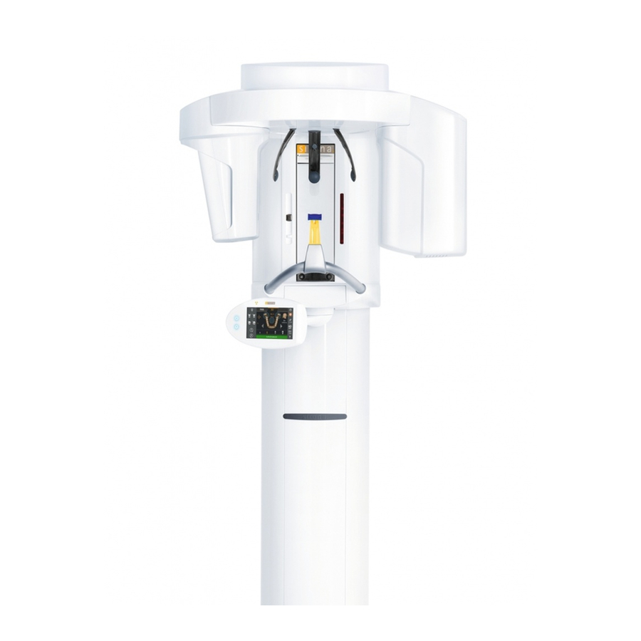
Summary of Contents for Sirona orthophos plus
- Page 1 NNKOMMR kÉï=ëáåÅÉW= loqelmelp=mäìë fåëí~ää~íáçå=fåëíêìÅíáçåë===== båÖäáëÜ...
- Page 2 Sirona Dental Systems GmbH ATTENTION ATTENTION Interference with electromedical devices by radio Use an ESD arm band. telephones: Connect this with the protective To guarantee the operational safety of electromedical ground wire. devices, the operation of mobile radio telephones in the medical practice or hospital area is prohibited.
-
Page 3: Table Of Contents
Sirona Dental Systems GmbH List of Contents 1 Possibilities of Installation......5 2 Installing the Unit ........6 3 Removing Transport Fixings .......8 4 Installing the X-Ray Tube Assembly ...9 5 Line Voltage..........10 6 Remote Control.........12 First installation possibility: Multitimer without spiral cable... - Page 4 Sirona Dental Systems GmbH 60 82 064 D 3297 D 3297.031.01.04.02...
-
Page 5: Possibilities Of Installation
Plus without remote control in the ATTENTION treatment room. Each wall plug must withstand a pull of 700 N (70 kp/ ORTHOPHOS Plus with remote control in the treat- 155pounds). ment room. Length of supplied special control cable about 15 me- Depending on the construction of the wall, suitable special ters (591”/49 feet). -
Page 6: Installing The Unit
2 Installing the Unit Sirona Dental Systems GmbH Installing the Unit Handles Installation hardware NOTE ATTENTION The power and control cables must have a play of at least Screw down the red transportation stabilization screw with 0.75 m vertically behind the column, so that system motion the unit in vertical position before removing the unit from the during operation is unhindered. - Page 7 Sirona Dental Systems GmbH 2 Installing the Unit Distances: see plan or dimension sheet • Note the information on wall condition on page 5. Move the unit to the desired location taking hold of the unit only at the rotation ring and/or column.
-
Page 8: Removing Transport Fixings
3 Removing Transport Fixings Sirona Dental Systems GmbH Removing Transport Fixings Installation hardware Unscrew cassette holder cover. Unscrew transportation stabilization screw A, and keep it in the adjustment kit and screw cassette holder cover back on. Unscrew transportation stabilization plate. Remove plate upwards. -
Page 9: Installing The X-Ray Tube Assembly
Sirona Dental Systems GmbH 4 Installing the X-Ray Tube Assembly Installing the X-Ray Tube Assembly Installation material Screw two Philips countersunk screws M5 into the threaded holes. ATTENTION When screwing in, be sure the tube assembly can be insert- ed into the slot all the way to the stop. -
Page 10: Line Voltage
5 Line Voltage Sirona Dental Systems GmbH Line Voltage • Rating: 1 kVA continuous ATTENTION ≤ 6V. • Max. voltage drop at 10 A ohmic load Replug the line voltage only with the unit switched off. Purchase a matching transformer which complies with these specifications in the destination country. - Page 11 Sirona Dental Systems GmbH 5 Line Voltage DX31 4.1 For exhibition only, without radiation ! On board DX31, set switch S88 to position 2. Disconnect plug X2 and fix as shown. 4.2 For exhibition only in USA/Canada, nominal line voltage 115V, without radiation! (No transformer required).
-
Page 12: Remote Control
6 Remote Control Sirona Dental Systems GmbH Remote Control NOTE If a door contact is required, connect to K10 according to Wiring References. First installation possibility: Multitimer without spiral cable ATTENTION ATTENTION The Multitimer with spiral cable is temporarily connected to Keep the spiral cable left over after installation at the cus- the unit's carriage for start-up. - Page 13 Sirona Dental Systems GmbH 6 Remote Control für Dübel Montagematerial Green marking here Remove the engaged cover. Remove cable at terminal strip K10 and insulate the flexible leads. Mark and drill four holes for chassis. Insert four wall plugs. Run and connect the ground wire A white or gray cable (D 1.5mm²...
- Page 14 6 Remote Control Sirona Dental Systems GmbH Undo the 3 screws on the back of the Multitimer and 19. Stick program foil in place. open the Multitimer. 10. Pull the helical cable off the Multitimer and connect the short cable A.
-
Page 15: Second Installation Possibility: Using The Multitimer With Spiral Cable
Sirona Dental Systems GmbH 6 Remote Control for wall plugs Installation hardware Green marking here Second installation possibility: Using the Multitimer with spiral cable Remove the engaged cover. - With free-hanging control cable: Mark and drill four holes for chassis. - Page 16 6 Remote Control Sirona Dental Systems GmbH 9. / 10. Loosen the clamp. Remove the cable tie and the shrinkdown plastic tubing from the control cable. The shielding of the control ca- ble must be visible. 10. Slide the control cable under the clamp from above.
-
Page 17: Starting-Up, Measurements And Controls For Usa/Canada Only
203±1 pulse, or equivalent. Power Supply Adequacy To assure that the ORTHOPHOS system performance is in accordance with Sirona specifications, an adequate power supply is essential. The Federal Performance Standard for diagnostic X-ray units, code of Federal Regulations, title 21 CFR, subchap- Radiation Protection ter J, mandates an adequate power supply. - Page 18 7 Starting-up, Measurements and Controls for USA/Canada only Sirona Dental Systems GmbH Multitimer ATTENTION For measurements and controls the remote installed Multi- Electrical Shock Hazard! timer must be connected directly to the unit's carriage Always turn unit OFF before connecting and disconnecting instead of the control cable's plug.
-
Page 19: Power Supply Adequacy (For Usa/Canada Only)
Sirona Dental Systems GmbH 8 Power Supply Adequacy (for USA/Canada only) Power Supply Adequacy (for USA/Canada only) door metal cover 300VAC 5. – 8. Terminal strip main cable see Operating Instructions To determine power supply adequacy, the line voltage drop during exposure must be measured. -
Page 20: Kv - Verification, Kv-Ramp During Panoramic Exposure (For Usa/Canada Only)
9 kV - Verification, kV-Ramp During Panoramic Exposure (for USA/Canada only) Sirona Dental Systems GmbH kV - Verification, kV-Ramp During Panoramic Exposure (for USA/Canada only) 20VDC com. KV– KV – 4. – 5. see Operating Instructions • During exposure the kV is encreased in the central re- •... - Page 21 Sirona Dental Systems GmbH 9 kV - Verification, kV-Ramp During Panoramic Exposure (for USA/Canada only) ramp 1.6s ramp max. 8.1V nominal 8.0V nominal 7.3V max. 7.7V min. 7.9V min. 6.9V 6.25 7.85 5.25s 8.85s 7.05s 14.1s complete P1 exposure time...
-
Page 22: Tube Current Verification (For Usa/Canada Only)
10 Tube Current Verification (for USA/Canada only) Sirona Dental Systems GmbH 10 Tube Current Verification (for USA/Canada only) 20mADC com. jumper MA– MA – see Service Manual Remove jumper from MA+/MA – test points. Switch unit OFF. Remove meter leads and replace jumper! If specified val- Connect digital ammeter to MA+ and MA–... -
Page 23: Exposure Time Verification For Panorama Exposure (For Usa/Canada Only)
Sirona Dental Systems GmbH 11 Exposure Time Verification for Panorama Exposure (for USA/Canada only) 11 Exposure Time Verification for Panorama Exposure (for USA/Canada only) Pulse counter com. of 110VAC/60Hz power receptacle Terminal strip main cable If specified value cannot be obtained, see Service Manual ”Checking Exposure Times”. -
Page 24: Checking And Adjusting The X-Ray Beam
12 Checking and Adjusting the X-Ray Beam Sirona Dental Systems GmbH 12 Checking and Adjusting the X-Ray Beam S1 rear of unit Orthophos vertical Adjustment Set Beam adjusting tool X-RAY Multitimer • The supporting tube of the forehead support must be ATTENTION vertical. -
Page 25: Selecting The Service Routine S.02
Sirona Dental Systems GmbH 13 Selecting the Service Routine S.02 13 Selecting the Service Routine S.02 X-RAY X-RAY 2 - 4 - 1 Memory X-RAY X-RAY X-RAY 3.20 e.g. • Following the self-adjustment routine of the unit, per- Actuate the “+” (kV/mA) button several times, until form Service Routine S.02 on the Multitimer (no rota-... - Page 26 13 Selecting the Service Routine S.02 Sirona Dental Systems GmbH 15 cm 12.7 cm Film Height Collima- 2 Status 1Pan 12.7 correct X-RAY 3.20 • Adjust the primary collimators 1 and 2 on the collimator Set beam correction via Allen screws B and C (eccen- wheel, one after the other.
-
Page 27: Checking The Aes (Automatic Exposure Selection)
Sirona Dental Systems GmbH 14 Checking the AES (Automatic Exposure Selection) 14 Checking the AES (Automatic Exposure Selection) X-RAY X-RAY 14.1 Set Service-Routine S.26 Set Service-Routine S.26 on the Multitimer (procedure analogous to that on page 25). • In the digital display the values 61 kV/16 mA oder 64 kV/16 mA flash, according to the film-screen system setting. -
Page 28: Perform Phantom Exposure
14 Checking the AES (Automatic Exposure Selection) Sirona Dental Systems GmbH Attach test block vertically Given AES test values X-RAY X-RAY Example 3.66V 14.2 Perform phantom exposure Attach special test block delivered as part of this unit to bottom of secondary collimator with adhesive tape. - Page 29 Sirona Dental Systems GmbH 14 Checking the AES (Automatic Exposure Selection) • The value printed on the film-screen system used ± 0.05V) must appear in the kV/mA display as the tenth voltage value measured. e.g. for type 20 film-screen system: read out voltage...
-
Page 30: 15 Phantom Radiograph
15 Phantom Radiograph Sirona Dental Systems GmbH 15 Phantom Radiograph Paper Film Paper Develop the film X-RAY Margin not exposed ±0.5mm 80mm±1mm • The unit must be in Panorama mode. Exit the service routine by switching OFF and then ON again. -
Page 31: 16 Final Work
Sirona Dental Systems GmbH 16 Final Work 16 Final Work Installation hardware • Attach cover. Be sure to follow the correct sequence. Place the front cover over the diaphragm wheel and attach from below with the two countersunk screws M4. - Page 32 – Fill in Serial-Nos. and Software Version in the enclosed Warranty Passport. Fill out remaining fields together with the customer. Send the filled out Form to Sirona. – FOR THE CUSTOMER remains in possession of customer. – FOR THE DEALER remains in customer file of Technical Service.
-
Page 33: Attention Installer (For Usa/Canada Only)
Sirona Dental Systems GmbH 17 Attention Installer (for USA/Canada only) ! 17 Attention Installer (for USA/Canada only) ! • Proper shielding of room and operator position is es- sential. Since these requirements vary from state to state it is the assembler's / installer's responsibility that all local radiation safety requirements are met. -
Page 34: Sample Of A Filled Out Form (For Usa/Canada Only)
18 Sample of a Filled out Form (for USA/Canada only) - Page 36 tÉ=êÉëÉêîÉ=íÜÉ=êáÖÜí=íç=ã~âÉ=~åó=~äíÉê~íáçåë=ïÜáÅÜ=ã~ó=ÄÉ=ÇìÉ=íç=íÉÅÜåáÅ~ä=áãéêçîÉãÉåíëK péê~ÅÜÉW=ÉåÖäáëÅÜ= mêáåíÉÇ=áå=dÉêã~åó a=POVTKMPNKMNKMQKMO===NNKOMMR ûKJkêKW= MMM=MMM fãéêáã¨=Éå=^ääÉã~ÖåÉ páêçå~=aÉåí~ä=póëíÉãë=dãÄe áå=íÜÉ=rp^W áå=`~å~Ç~W SM=UO=MSQ=a=POVT c~Äêáâëíê~≈É=PN páêçå~=aÉåí~ä=póëíÉãë=ii` páêçå~=`~å~Ç~ lêÇÉê=kç SQSOR=_ÉåëÜÉáã QUPR=páêçå~=aêáîÉI=pìáíÉ=NMM PORM=oáÇÖÉï~ó=aêáîÉ=J=råáí=R dÉêã~åó `Ü~êäçííÉI=k`=OUOTP jáëëáëë~ìÖ~I=låí~êáç=iRi=RvS ïïïKëáêçå~KÅçã `~å~Ç~...
Need help?
Do you have a question about the orthophos plus and is the answer not in the manual?
Questions and answers