
Related Manuals for EdilKamin IDROPELLBOX 30


Summary of Contents for EdilKamin IDROPELLBOX 30
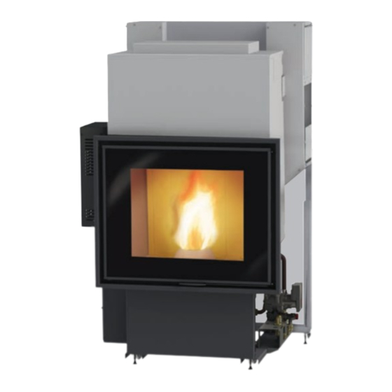
- Page 1 IDROPELLBOX 30 WOOD PELLET BOILER-FIREPLACE Installation, use and maintenance page 2...
-
Page 2: Table Of Contents
Maintenance Troubleshooting The original language of this manual is Italian The undersigned EDILKAMIN S.p.A., with registered office in Via Vincenzo Monti 47 - 20123 Milan (Italy) - Tax ID Code and VAT number 00192220192 Hereby declares, under its sole responsibility, that:... -
Page 3: Introduction And Readers Of This Manual
Commissioning is required for activation of the Edilkamin The diagrams provided in this manual are for illustration manufacturer warranty. The warranty is only valid in the purposes only: they do not always strictly refer to your country where the product was bought. -
Page 4: Safety Information
DO NOT product: specifically, neither Edilkamin nor PLACE LAUNDRY ON THE APPLIANCE. the retailer are liable for damage resulting DO NOT PLACE DRYING RACKS WITHIN from incorrect installation or maintenance. -
Page 5: Dimensions
DIMENSIONS IDROPELLBOX 30 Cold H heating return 3/4” heating delivery 1/2” fitting fitting 3/4” fitting Ø 10 smoke outlet Ø 10 smoke outlet USER/INSTALLER... -
Page 6: Technical Data
Protection Fusibile 4 AT, 250 Vac 5x20 The above data is for guidance only and was measured during certification by a notified body. EDILKAMIN s.p.a. reserves the right to modify the product without notification in the interests of improvement. USER/INSTALLER... -
Page 7: Unpacking
UNPACKING PREPARATION AND UNPACKING PACKAGING The packaging materials are neither toxic nor noxious In the stove you will find: and do not require special disposal. • remote control, The user is responsible for storing, disposing of and • warranty certificate, recycling them in a regulatory fashion. - Page 8 UNPACKING SHIFTING THE PRODUCT The fireplace is equipped with four casters for facilitating its handling. Lower the feet by turning them to use the wheels. After positioning the fireplace, reposition the feet. The feet are used to distance the fireplace from the floor and to level the hearth. casters Handling should be done using wheels only...
-
Page 9: Fume Outlet Direction
FUME OUTLET DIRECTION The product has a rear fume discharge outlet but is also configured to have it on the upper side. To orient the outlet upwards; (please note that the pellet loading hatch cannot be used from the side) •... -
Page 10: Water Circuit Installation
WATER CIRCUIT INSTALLATION HYDRAULIC CONNECTIONS VENT Idropellbox 30 has an incorporated hydraulic kit. During normal operations vent is automatic. During installation, the It includes: technician must check the functionality of • a circulator pump; the automatic vent and assess whether a •... - Page 11 WATER CIRCUIT INSTALLATION PUMP SPECIFICATIONS Fig. 1: leds The pump has no adjustment devices. Fig. 2: Adjustments are made via the micro processor on the boiler stove: “begin” at the lowest speed and make adjustments based on the progression of the water temperature.
-
Page 12: Terminal Board
TERMINAL BOARD TERMINAL BOARD Sul lato sinistro (tolto il coperchio protettivo avvitato A terminal board is mounted just above the electronic board, on the left-hand side (remove the protective cover fastened with two screws). The terminal board includes low and high voltage. Examples of possible connection configurations are shown below. -
Page 13: Installation
INSTALLATION REMARKS ON INSTALLATION NOTE Note that: To load the pellets and perform maintenance, there must • installation must be carried out by authorised be at least two doors on the left-hand and right-hand technical personnel; sides (170x55 cm). • The appliance must be installed and operated See following page. - Page 14 INSTALLATION Distance from flammable wall not requested (0 cm). If the air vent is not connected to the outside, leave 4 cm. Minimum width “Insert the aeration grilles and side openings (55x170 cm doors) to be able to load the pellets into the tank, view the pressure gauge, for easier access to the ignition button, maintenance, etc.
- Page 15 INSTALLATION Protection from heat and safety clearances The surfaces of the building that are adjacent to the product must be protected against overheating. The insulation to be used will depend on the type of surface in question. The appliance must be installed in accordance with the following safety instructions: - no flammable materials may be kept closer than 10 cm to the sides and back...
- Page 16 INSTALLATION FLUE SYSTEM(Smoke duct, flue THE SMOKE DUCT chimney pot) Further to the general prescriptions for the smoke duct This chapter has been drawn up pursuant to European and flue, the smoke duct: standards EN 13384, EN 1443, EN 1856 and EN 1457. •...
- Page 17 INSTALLATION THE FLUE: AIR INTAKE FOR COMBUSTION Further to the general prescriptions, the flue must In general, we suggest two ways to ensure a proper • only be used to discharge smoke flow of combustion air. Air must come from the outside* •...
- Page 18 The electrical system must be compliant; check the operation of the earth in particular. Edilkamin is not responsible for malfunctions resulting from an improperly earthed system. The power line must be of adequate section for the power of the appliance.
- Page 19 INSTALLATION Facings, gather hood and vents Face the product only after having completed the following steps: • connection of the product to the smoke outlet and air intake; • inspection of the product when hot; • check to verify whether the product is levelled.
-
Page 20: Introduction About Use
USER INSTRUCTIONS LOADING THE PELLETS INTO THE TANK FIRST IGNITION (COMMISSIONING) Load the pellets from the right-hand or left-hand hatch, PHASES as decided during the installation phase. • Make sure you have read and understood this manual. • Remove all flammable materials from the appliance (manuals, labels, etc.). - Page 21 USER INSTRUCTIONS - DISPLAY INTERFACE The user interface is the remote control but, should this device not be available, you can control the product with the button located on the left side (see figure below): WITH THE PRODUCT OFF 1. Press the button for 2” to switch the product on. 2.
- Page 22 This is an approximate value, since it depends on both the type of batteries and the intensity of use. Edilkamin and the reseller will not consider claims for battery life under any circumstances. If the battery charge is low, a warning displays at the top left (see the paragraph on “If problems arise”).
- Page 23 USER INSTRUCTIONS The display will show: * The product is programmed by default with a delta of +/- 1 °C to • the symbols of the heat request (radiator, tap, optimise comfort. pump activation); The technician can change this setting during commissioning to suit •...
- Page 24 USER INSTRUCTIONS SIMPLIFIED USE after first ignition In default mode, with the product connected to the power supply, press the ON/OFF button on the display to “activate” the boiler stove and adjust the desired room temperature with the +/- buttons. The boiler stove will switch on and off and will adjust its power automatically to keep the set temperature.
- Page 25 USER INSTRUCTIONS The product operates with the POSSIBLE MODES (described below): • OFF MODE • ON MODE • STAND BY MODE • ALARM MODE OFF MODE The product is “disabled” and does not produce heat. The product may turn on only for the anti-freeze function (described on this page).
- Page 26 USER INSTRUCTIONS ON MODE with STAND BY While in stand-by mode, and ON, the In ON mode with STAND BY (the product is “active” product turns on only if there is a heat but with stand by function enabled) the product turns request.
- Page 27 USER INSTRUCTIONS By the remote control you can: Switching on and off will take a few minutes, during which the flame must appear or go • Switch from OFF to ON modes, by off. Just wait without taking any action. pressing and holding the ON/OFF button During ignition, the display shows the text •...
- Page 28 USER INSTRUCTIONS Menu Stand by Press the “M” button to display the menu. When the Stand by function is active, in automatic When the menu displays, the buttons have the and crono mode, the product shuts off when the following functions: temperature setpoint is reached and turns on again “+”...
- Page 29 USER INSTRUCTIONS Crono The following screen will appear. Scroll to “ENABLE” (underlined) using the “+/-” buttons. When the Crono function is active, the user sets a To enable the Crono function to 7 days a week or temperature setpoint and a time zone for which that on single days (“ENABLE”...
- Page 30 USER INSTRUCTIONS To combine one of the three temperatures To set the temperature setpoints (“TEMP” on to a time period (“SET” on the display), from the the display), from the Crono function, press the “OK” Crono function, press the “OK” button. The following button.
- Page 31 USER INSTRUCTIONS The second screen (accessible by pressing the “OK” To view/change the settings (“CHANGE” on button from the first screen) allows you to set the start the display), from the Crono function, press the “OK” and end time of the time period matching the chosen button.
- Page 32 USER INSTRUCTIONS Load Pellets Allows you to load pellets after the screw feeder has emptied following a no-pellets alarm. Useful for the technician during commissioning. Available only in the OFF state. If you attempt to activate the function in other states, access is not granted. To access the function from the main menu (as indicated in the Menu section above), press the M button.
- Page 33 USER INSTRUCTIONS Date/Time Beep Sets the current date/time. Allows you to enable/disable the beep. This displays the first time the remote control is To access the function from the main menu (as activated with the stove powered on, or by selecting indicated in the Menu section above), press the M the option in the menu.
- Page 34 USER INSTRUCTIONS Setting water Temperature (“TEMPERATURE” on the display) STAND BY Allows you to set the boiler temperature and the CRONO accumulator temperature. If the external probe is TEMPERAT CARICO PLT active, it allows you to set the climatic curve instead of LANGUAGE the boiler temperature.
-
Page 35: Maintenance
MAINTENANCE Disconnect the product from the power supply. Failure to service the product properly will prevent it from working properly. Any problems due to failure in servicing the stove will void the warranty. DAILY MAINTENANCE Do not dump the cleaning residue into the pellet tank. These operations must be done with the product off, Once it is refitted, make sure that the ash tray is properly cold and preferably disconnected from the mains. - Page 36 MAINTENANCE DAILY MAINTENANCE manually pull/push for 3/4 times the turbulator knob, located at the top right-hand side (A) 2. Open the combustion chamber door (P) 3. Remove the grille (B) 4. Remove the two-part burning pot (C) 5. Remove the ash tray (D) 6.
- Page 37 For any spare parts, contact your dealer or technician. flue every 3 months. Using non-original spare parts may damage the appliance and relieves Edilkamin of all liability for You should clean the chimney system at least once a damage resulting such use.
- Page 38 TROUBLESHOOTING If problems occur, the product shuts itself off automatically. The display will show the reason (see below). Do not disconnect from the power supply. To start the product up again, allow the shut-down procedure to complete, then press the ON/OFF button.
-
Page 39: Troubleshooting
TROUBLESHOOTING MESSAGE PROBLEM SOLUTION • Check the type of pellet (contact the technician if in Shut-down due to exceeding doubt) maximum smoke temperature • contact the technician Switching OFF due to excessive • see HO7 overheating of the product Shut down due to gear motor •... - Page 40 If the water in the boiler stove reaches a temperature of 85°C, the boiling stove shuts down without switching to alarm mode. The text STBY appears on the display next to the room temperature. The product is working, but it must be serviced by an authorised Edilkamin technician. MAINTENANCE (SIGNAL THAT DOES NOT CAUSE SHUT-DOWN) A wrench symbol is shown on the display after 2000 hours of operation.
- Page 44 *941927-GB* w w w . e d i l k a m i n . c o m cod. 941927-GB 08.18/C...
Need help?
Do you have a question about the IDROPELLBOX 30 and is the answer not in the manual?
Questions and answers