Table of Contents
Advertisement
Available languages
Available languages
Advertisement
Table of Contents

Related Manuals for EdilKamin SIDE 50x50


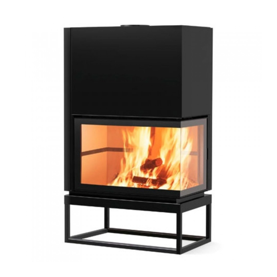
Summary of Contents for EdilKamin SIDE 50x50
- Page 1 SIDE SIDE 2 Installazione, uso e manutenzione pag. Installation, use and maintenance page 15 Installation, usage et maintenance pag. 28 Instalación, uso y mantenimiento pag. 41 Installations-, Betriebs- und Wartungsanleitung Seite 54 Instalação, uso e manutenção pag. 67...
- Page 2 In caso di anomalie si rivolga subito al rivenditore presso cui è stato acquistato cui va consegnata copia del libretto di garanzia e Messa in servizio/collaudo della garanzia. normative. Presso il rivenditore, al numero verde o sul sito www.edilkamin.com può trovare il nominativo del Centro Assistenza più vicino. - N.B.
-
Page 3: Schema Di Funzionamento
SCHEMA DI FUNZIONAMENTO La struttura è costituita da un corpo di lamiera d’acciaio com- pleta di telaio di supporto (con possibilità di essere rimosso per posizionare il focolare ad altezza cm 8 rispetto il pavimento). Il rivestimento interno del focolare è in refrattario con piano fuoco a catino, per un corretto contenimento dell e braci. - Page 4 DIMENSIONI Ø 20 14,5 47,5 SINISTRO Ø 25 87,5 DESTRO Ø 25 87,5 SIDE 2 47,5 47,5 Ø 25...
- Page 5 CARATTERISTICHE CARATTERISTICHE TERMOTECNICHE SIDE 50x50 SIDE 2 SIDE 3 Potenza nominale Rendimento 80,9 81,9 80,1 80,1 80,1 Ø Uscita fumi femmina Dimensioni interne focolare Ø uscita aria calda canalizzazione 1,8 -2,4 1,6 - 4,5 1,6 - 4,2 Volume riscaldabile *...
-
Page 6: Aria Per La Combustione
LA TECNOLOGIA ARIA PER LA COMBUSTIONE bocchette uscita aria di Per poter far funzionare il caminetto in modo corretto è essen- riscaldamento ziale far pervenire l’aria di combustione al focolare tramite una tubazione che collega l’ambiente esterno con una delle apposite prese (A Per agganciare detta tubazione, deve essere applicato alla presa che si intende utilizzare un raccordo di diametro 10 cm... -
Page 7: Avvertenze Importanti
Linee elettriche fuori dal campo d’irraggiamento, a una distanza di almeno 1 cm dal rivestimento Edilkamin non risponde di conseguenza nell’area d’incasso del focolare non stesso. degli oneri derivati sia da interventi di devono essere presenti linee elettriche demolizione che di ricostruzione anche L’intercapedine che isola gli elementi... - Page 8 Per canne fumarie non di nuova realizza- Eventuali cambiamenti di sezione sono Edilkamin non risponde di conseguenza zione o troppo grandi si consiglia l’intu- ammessi solo all’uscita del caminetto e degli oneri derivati sia da interventi di non per esempio all’innesto nella canna...
- Page 9 INSTALLAZIONE Kit tre/bis locale caminetto, più due L’aria calda prodotta dal caminetto viene attigui immessa nei locali da riscaldare tramite bocchette di mandata collegate ai fori del mantello sul coperchio del mantello con tubi di alluminio Ø 14 cm. le apposite fascette E’...
-
Page 10: Circolazione Aria Calda
CIRCOLAZIONE ARIA CALDA ARIA PER IL RISCALDAMENTO CIRCOLAZIONE A CONVEZIONE NATURALE L’aria ambiente entra dalle prese laterali (12 ricavate alla base del mantello, si scalda, sale per convezione lungo l’intercapedine sul retro focolare ed esce calda dai boc- chettoni sul coperchio del mantello stesso (14 delle prese alla base del mantello deve essere consentito un caso di rivestimento). - Page 11 INSTALLAZIONE Il collegamento con l’esterno, di sezione per il buon funzionamento del caminet- realizzato. Detto collegamento, deve raccordare di- rettamente con l’esterno il meccanismo Il meccanismo, consegnato separatamen- te, può essere montato sia a destra che a sinistra del caminetto. Per il montaggio procedere come segue: smo di regolazione aria utilizzando le Fig.
- Page 12 CORNICE CONTORNO BOCCA - SIDE 3 (optional) CORNICE CONTORNO BOCCA - SIDE 3 (optional) La cornice “optional” viene consegnata in imballo di cartone La cornice “optional” viene consegnata in imballo di cartone scomposta nei seguenti elementi: scomposta nei seguenti elementi: - Z: n°...
-
Page 13: Istruzioni Per L'uso
ISTRUZIONI PER L’USO Funzionamento del focolare a portel- Accensione a focolare freddo lone aperto 1. Controllare che il letto di cenere esi- La combustione è stata ottimizzata dal In caso di funzionamento a portellone stente non sia troppo alto. riguarda la concezione del focolare e aperto, il focolare dovrà... - Page 14 ISTRUZIONI PER L’USO Un ulteriore suggerimento: Per l’accensione iniziale del focolare, (SOLO per SIDE 50x50 e SIDE 2) Il portellone è dotato di un contrappeso utilizzate sempre i ciocchi di legna più - aprire ad anta il portello agendo, tarato per garantire una chiusura auto- piccoli.
- Page 15 Dear Sir/Madam, www.edilkamin.com. and click on DEALERS. NOTE booklet, glove, technical data sheet/CD). Commissioning/ testing - N.B. DECLARATION OF CONFORMITY - 15...
- Page 16 FUNCTIONING DIAGRAM The structure is composed of a steel plate body complete with supporting framework (which can be removed to position the The structure is complete with a shell which creates a cavity for the circulation of the heating air. The heating air can circulate by natural convection (version N) or by forced ventilation (version V).
- Page 17 DIMENSIONS Ø 20 14,5 47,5 LEFT Ø 25 87,5 RIGHT Ø 25 87,5 SIDE 2 47,5 47,5 Ø 25 - 17...
- Page 18 Weight including packing The volumes heated are indicative, since they depend on the position of the product, the insulation of the building and environ- mental factors. EDILKAMIN s.p.a. reserves the right to change the products at its discretion without notice. - 18...
-
Page 19: Air For Combustion
THE TECHNOLOGY AIR FOR COMBUSTION hot air exit vents bustion air to be introduced into by means of a pipe which links To hook up the said piping, a 10 cm connection must be ap- plied to the chosen vent (10 counterweight The inner section of the piping be at least 125 cm along its... -
Page 20: Installation
INSTALLATION IMPORTANT ADVICE REGARD- Introduction ING THE INSTALLATION Flooring in combustible materials must cording to the instructions given below, Other than that described in this docu- mentation, you are also asked to note the system depend on correct installation. must be: following UNI standards: at the front: tions carefully. - Page 21 Any difference in section is allowed which must be carried out after success- not particularly large, it is advisable to ful testing. Edilkamin will not be liable for any a suitable diameter and suitable insula- demolition or reconstruction costs even tion.
- Page 22 INSTALLATION adjacent released into the rooms to be heated by the nozzles connected to the holes on the holes in the shell cover of the hood with aluminium pipes Ø 14 cm. with the bands provided It is essential to guarantee the return of - set the frames with the two nozzles is installed by means of grills at the base heated...
- Page 23 CIRCULATION OF HOT AIR AIR FOR HEATING connection grille CIRCULATION BY NATURAL CONVECTION sensor The environmental air enters from the side vents (12 released, hot, from the vents on the cover of the shell itself (14 regulator For this mode, the caps of the vents at the base of the shell must be removed and the environmental air must be able to clamp CIRCULATION BY FORCED VENTILATION...
- Page 24 INSTALLATION F-G) it is therefore essential to ensure this intake capacity. The said connection must directly link The mechanism, delivered separately, with screws and apply the regulation Fig. C mechanism using the same screws. - Take care to seal the points where air dispersion could occur.
- Page 25 AIR VENT FRAME - SIDE 3 (optional) AIR VENT FRAME - SIDE 3 (optional) The optional frame is delivered unassembled in cardboard packaging containing the following elements: Fig 1 - The frame group Fig 2 holes contemplated in the structure) Fig 3 Fig 4 with the round-headed screws...
-
Page 26: Instructions For Use
INSTRUCTIONS FOR USE Fuel and heating capacity Fireplace functioning with the door open 1. Check that there is not too much ash Combustion has been optimised from a technical viewpoint both as regards the in the bowl. it must be kept constantly under control. air intake, and as regards the emissions. - Page 27 INSTRUCTIONS FOR USE A further suggestion: (ONLY for SIDE 50x50 and SIDE 2) H - I) small pieces of wood. - open the front door, using the tool The door has a counterweight calibrated to guarantee automatic closure. the latch plate located on the upright at the side of the door (turn it 90°).
- Page 28 Gentile Signora / Egregio Signore Madame, Monsieur, site internet www.edilkamin.com à la rubrique REVENDEUR. NOTE - Mise en service/test - N.B.: DECLARATION DE CONFORMITÉ - 28...
-
Page 29: Schéma De Fonctionnement
SCHÉMA DE FONCTIONNEMENT ner le foyer à une hauteur de 8 cm du sol). une sole foyère en forme de cuvette, pour un meilleur contenu des braises. pour la circulation de l’air de chauffage. L’air pour le chauffage peut circuler à convection naturelle L’air primaire de combustion (A) entre à... - Page 30 DIMENSIONS Ø 20 14,5 47,5 GAUCHE Ø 25 87,5 DROITE Ø 25 87,5 SIDE 2 47,5 47,5 Ø 25 - 30...
- Page 31 CARACTERISTIQUES CARACTÉRISTIQUES THERMOTECHNIQUES SIDE 50x50 SIDE 2 SIDE 3 Puissance utile Rendement 80,9 81,9 80,1 80,1 80,1 Dimensions internes du foyer Ø sortie de l’air chaud 1,8 -2,4 1,6 - 4,5 1,6 - 4,2 Volume de chauffe * Poids avec emballage...
-
Page 32: Air Pour La Combustion
LA TECHNOLOGIE AIR POUR LA COMBUSTION Raccords de sortie de l’air de chauffage diamètre(10 Le tuyau doit conserver une section utile passante d’au moins Inspection du 125 cm2 tout au long de son parcours. contre-poids leur couvercle. Prises pour l’air Vanne papillon de combustion L’air pour la combustion doit arriver au foyer à... -
Page 33: Mises En Garde Importantes
INSTALLATION MISES EN GARDE IMPORTANTES Préliminaire Sol en proximité de la cheminée normes UNI: bois: conditions d’installation de front: - en correspondance du plan de combu- les cas à 50 cm minimum latéralement: instructions et dans ce cas tout droit à la En particulier: - en correspondance du plan de combu- stion du sol plus de 20 cm et dans tous... - Page 34 INSTALLATION Conduit pour la fumée Sui- - avoir une section constante, un par- cours le plus vertical possible et ne pas - construction de la contre-hotte circulaire; dans le cas de sections rectan- - avoir une section interne avec une su- horizontales ou en contre-pente doivent section sont admis seulement à...
- Page 35 INSTALLATION kit trois/bis pièce d’installation de la cheminée, plus deux pièces contigües vers les bouches de refoulement raccor- trous du manteau nium de 14 cm de diamètre. Il est indispensable de garantir le retour - sceller les châssis avec un raccord des de l’air dans la pièce d’installation de la pièces à...
- Page 36 CIRCULATION DE L’AIR CHAUD AIR POUR LE CHAUFFAGE raccord CIRCULATION À CONVECTION NATURELLE grille sonde ventilateur 1 à la page 16). Pour le fonctionnement dans cette direction, bornes CIRCULATION AVEC VENTILATION FORCÉE kit pour installations de l’appareil situé sous le monobloc Fig.
- Page 37 INSTALLATION , est absolument Ce raccordement doit relier directement suivante : vis. Fig. C l’air. du conduit de la prise d’air une grille Fig. D du sol (il ne peut pas provenir du haut). engagement en faveur d’un environne- ment pur, en respectant les indications Fig.
- Page 38 CADRE CONTOUR BOUCHE - SIDE 3 (en option) carton : - Z : 4 rondelles plates D.5 Fig. 1 - Ensemble cadre Fig. 2 Fig. 3 Fig. 4 contre-chape à l'aide des vis Fig. 5/6 inférieur cadre contour bouche V-Y-Z supérieur - 38...
-
Page 39: Instructions Pour L'utilisation
INSTRUCTIONS POUR L’UTILISATION porte ouverte En cas de fonctionnement à porte ouver- au-dessous du bord de la porte. et de sa relative alimentation d’air, tant Si le lit de cendres devient trop haut vous invitons à soutenir notre engage- ment en faveur d’un environnement tombent en dehors du foyer. - Page 40 INSTRUCTIONS POUR L’UTILISATION Un dernier conseil: Nettoyage de la vitre Installation des contre-poids (SEULEMENT pour SIDE 50x50 et SIDE 2) La porte est pourvue d’un contre-poids ture dans les meilleurs temps. pour alimenter à nouveau le feu. - après le nettoyage, refermer en agissant foyer;...
- Page 41 - Puesta en servico/ensayo mismo a las normativas. En el vendedor, en el número verde o en el sitio internet www.edilkamin.com puede encontrar el nominativo del vendedor más cercano. - instalaciones incorrectas, mantenimientos realizados incorrectamente, el uso impropio del producto, exoneran a la empresa - NOTA DECLARACIÓN DE CONFORMIDAD...
-
Page 42: Esquema De Funcionamiento
ESQUEMA DE FUNCIONAMIENTO La estructura está compuesta por un cuerpo realizado en lámina respecto al pavimento). El revestimiento interno del hogar está realizado en material refractario con un plano de fuego de cúpula, para una correcta El aire primario de combustión (A) entra en la base del plano La cantidad del aire primaria es regulable según el tiro del encuentra instalado sobre el borde delantero del plano fuego. - Page 43 DIMENSIONES 14,5 Ø 20 47,5 IZQUIERDA Ø 25 87,5 DERECHA Ø 25 87,5 SIDE 2 47,5 47,5 Ø 25 - 43...
- Page 44 CARACTERÍSTICAS CARACTERÍSTICAS TERMOTÉCNICAS SIDE 50x50 SIDE 2 SIDE 3 Potencia útil Rendimiento 80,9 81,9 80,1 80,1 80,1 Salida humos Ø Ø tubo de humos para altura sup. 5 m 1,8 -2,4 Dimensiones internas del hogar 1,6 - 4,5 1,6 - 4,2...
-
Page 45: Aire Para La Combustión
LA TECNOLOGÍA AIRE PARA LA COMBUSTIÓN Bocas de salida de aire de calentamiento A) situada Para enganchar dicha tubería, debe aplicarse a la toma una Inspección de contrapeso das con una tapa. de aire complementaria. Tomas para el aire de Válvula de mariposa combustión Sin la válvula de mariposa montada correctamente (ver pág. -
Page 46: Instalación
En las paredes y en los techos compren- encuentran fuera del campo de irradia- didos en el área de encaje del hogar no Edilkamin no responde por tanto de los daños derivados tanto de intervenciones del propio revestimiento. El intersticio entre los elementos ornamentales y el tuosas. - Page 47 - estar al servicio de un único hogar (chi- Edilkamin no responde en consecuencia menea o estufa). Para tubos de salidas de de las gastos derivados de intervencio- zontales o en contrapendencia. Eventua-...
- Page 48 INSTALACIÓN El aire caliente producido por la estufa Kit tres/bis local chimenea, más dos contiguos cios del revestimiento con tubos de aluminio de Ø 14 cm. con las abrazaderas correspondientes Es indispensable garantizar el retorno del mismo aire al local en donde se - montar en la parte alta de la contra las rejillas hasta la base de los muros o campana una ranura “G1”...
- Page 49 220V Fig. 11 CIRCULACIÓN A VENTILACIÓN FORZADA 11-12-13) (SOLO para la versión SIDE 50x50 y SIDE 2) - regulador - sonda - La caja de aire debe encontrarse situada debajo de la base Fig. 12 caja de aire.
- Page 50 INSTALACIÓN necesaria para el buen funcionamiento de la estufa, por lo tanto debe realizarse obligatoriamente. El mecanismo, entregado por separado, Para el montaje proceder de la siguiente manera: tornillos y aplicar el mecanismo de tornillos. Fig. C - Proteger bien el sellado de los puntos Se aconseja aplicar fuera del conducto Fig.
- Page 51 MARCO DE CONTORNO DE BOCA - SIDE 3 (opcional) separada en los siguientes elementos: - Z: 4 arandelas planas D.5 Fig 1 - Grupo de marco Fig 2 Fig 3 Fig 4 contracapa mediante tornillos, cabeza abombada Fig 5/6 rior (B) y superior (C) del marco mediante tornillos de cabeza inferior marco de contorno de boca V-Y-Z...
-
Page 52: Instrucciones Para La Instalación
INSTRUCCIONES PARA LA INSTALACIÓN Funcionamiento del hogar con la Encendido con el hogar frío puerta abierta En caso de funcionamiento con la puerta abierta, el hogar deberá ser tenido con- por debajo del borde de la puerta. stantemente bajo control. Desde el hogar Si la capa de ceniza se convierte en partículas de brasas incandenscentes. - Page 53 Limpieza del vidrio Instalación de los contra pesos Para el encendido inicial del hogar, (SOLO para SIDE 50x50 y SIDE 2) utilizar siempre las piezas de leña más - abrir el portillo abatible usando la La puerta está dotada por un contra herramienta correspondiente (mano fría...
- Page 54 Sehr geehrte Kundin, sehr geehrter Kunde, wir danken Ihnen und beglückwünschen Sie zur Wahl unseres Produkts. und in völliger Sicherheit zu nutzen. Inbetriebnahme/Abnahme - am oberen Teil der Verpackung Side 3 dar. - 54...
- Page 55 FUNKTIONSSCHEMA Die Struktur besteht aus einem Stahlblechkörper mit Stützrah- men (welcher für die Positionierung des Feuerraums auf einer Die Innenverkleidung des Feuerraums besteht aus feuerfestem dass die Glut korrekt aufbewahrt wird. oder durch Zwangszirkulation (Ausführung V) zirkulieren. Die Zufuhr der Verbrennungsluft in den Feuerraum wurde be- sonders durchdacht konzipiert, um eine optimale Verbrennung, Primäre Verbrennungsluft (A) tritt durch den Boden des vorderen Rand der Feuerablage installiert ist.
- Page 56 ABMESSUNGEN Ø 20 14,5 47,5 LINKS Ø 25 87,5 RECHTS Ø 25 87,5 SIDE 2 47,5 47,5 Ø 25 - 56...
- Page 57 Nennleistung Leistungsgrad 80,9 81,9 80,1 80,1 80,1 Ø Rauchauslass Buchse 1,8 -2,4 1,6 - 4,5 1,6 - 4,2 Durchmesser Luftzufuhrrohr (Innenrohr) EDILKAMIN s.p.a. behält sich das Recht vor, die Produkte ohne Vorankündigung und nach eigenem Ermessen zu ändern. - 57...
- Page 58 DIE TECHNOLOGIE VERBRENNUNGSLUFT Ausgangsstutzen Heizluft einer der an den Seiten (Abb. 6) und unten (Abb. 7) sitzenden A) verbindet, eingeführt werden. die verwendet werdens soll, eine Verbindung mit einem Durch- Inspektion messer von 10 cm angebracht werden. Gegengewicht (10 - Abb. 8). Die Verrohrung muss einen Nutzdurchmesser von mindestens 125 cm entlang ihres gesamten Verlaufs haben.
-
Page 59: Wichtige Hinweise
Abnahme auszuführen. keine elektrischen Leitungen vorhanden sein. einem Abstand von mindestens 1cm von Edilkamin haftet folglich nicht für Der Zwischenraum, der die Zierelemen- lungseingriffen, selbst wenn diese auf Austauscharbeiten von möglicherweise te und die Verkleidung trennt, muss so fehlerhaften Feuerraumteilen zurückzu-... - Page 60 Installation des Monoblocks feuerfeste Platten geschützt werden, Falls eine Verbindung an eine von welche nicht aneinandergeschoben son- Edilkamin vorgefertigte Verkleidung dern mit entsprechendem Abstand von erfolgen soll, muss für die Bestimmung mindestens 1 cm von letzterem errichtet prüft werden, mit welcher Verkleidung Die Rauchfangverkleidung kann mit er fertiggestellt wird.
- Page 61 INSTALLATION Bausatz 3/bis Kaminraum plus zwei angrenzende Räume - befestigen Sie die zwei Verbindungen Zufuhrstutzen, die an die Löcher auf der - führen Sie die zwei Rohre (21) ein Ø 14 cm verbunden sind, zugeführt. Der Rücklauf derselben Luft durch Git- Schellen - mauern Sie die Rahmen mit der Ver- Der Rohrdurchmesser darf nicht gerin-...
- Page 62 Netz 220V Abb. 11 ZIRKULATION MIT ZWANGSVENTILATION Bausatz für die Geräteinstallation als Monoblock (Abb. 11-12-13) (NUR für die Ausführung SIDE 50x50 und SIDE 2) Die Zwangszirkulation der Warmluft erfolgt mittels Einsatz des - Regler - Sonde Für die Installation wie folgt verfahren: Abb.
- Page 63 INSTALLATION Außenlufteintritt (Abb. C-D-E-F-G) obligatorisch. Diese Verbindung muss den Luftregel- mechanismus (10 - Abb. D) direkt mit kann sowohl rechts als auch links vom - Den mit Schrauben befestigten Deckel (A - Abb. C) abnehmen und den Luftre- gelmechanismus mit denselben Schrau- ben anbringen.
- Page 64 RAHMEN DER KAMINÖFFNUNG - SIDE 3 (optional) RAHMEN DER KAMINÖFFNUNG - SIDE 3 (optional) Elemente zerlegt geliefert: - A: 5 Stück Befestigungsplatten für den unteren Rahmen der - Z: 4 Stück Flachscheiben D.5 Abb. 1 Abb. 1 Abb. 1 Abb. 2 - Die 5 Befestigungsplatten (A) durch die mitgelieferten (hierfür die vorgesehenen Löcher an der Struktur verwenden) Abb.
- Page 65 GEBRAUCHSANWEISUNG Brennstoff und Heizleistung Funktion des Feuerraums bei geöffne- Anzünden bei kaltem Feuerraum ter Tür 1. Überprüfen, dass das vorhandene Die Verbrennung wurde aus technischer Falls der Feuerraum mit geöffneter Tür Sicht optimiert, sowohl in Bezug auf Aschebett nicht zu hoch ist. dazugehörigen Luftversorgung als auch werden.
- Page 66 GEBRAUCHSANWEISUNG Ein weiterer Tipp: Glasreinigung (Abb. L-M) Installation der Gegengewichte (Abb. (NUR bei SIDE 50x50 und SIDE 2) H-I) dung des Feuerraums immer kleinere Die Tür ist mit einem tarierten Gegenge- dazugehörigen Werkzeug (mitgelieferter wicht ausgestattet, um ein automatisches Diese brennen schneller und bringen den Feuerraum so in kürzerer Zeit auf die...
- Page 67 Estimada Senhora / Estimado Senhor no link CENTROS ASSISTÊNCIA TÉCNICA. garantia. as normativas. - na parte alta da embalagem - Importante: DECLARAÇÃO DE CONFORMIDADE - 67 - 67...
-
Page 68: Esquema De Funcionamento
ESQUEMA DE FUNCIONAMENTO as brasas e cinzas. um vidro sempre limpo. O ar primário de combustão (A) entra na base da lareira a partir de uma superfície livre de brasas. da base da lareira. diminuí-la. O ar secundário de combustão (B) e de limpeza do vidro en- Fig. - Page 69 DIMENSÕES 14,5 Ø 20 47,5 ESQUERDA Ø 25 87,5 DIREITA Ø 25 87,5 SIDE 2 47,5 47,5 Ø 25 - 69 - 69...
- Page 70 1,6 - 4,5 1,6 - 4,2 Peso incluído embalagem Diâmetro conduto tomada de ar edifício e de factores ambientais. EDILKAMIN S.p.A. reserva-se o direito de alterar sem aviso prévio e a seu exclusivo critério os produtos. - 70 - 70...
- Page 71 A TECNOLOGIA AR PARA A COMBUSTÃO Bocais de saída do ar de aquecimento Inspecção contrapeso a tampa fornecida de fábrica. tomada de ar adicional. Tomadas para o ar de Válvula de borboleta combustão Fig. 6 mento. Regulação da válvula de borboleta Fig.
-
Page 72: Advertências Importantes
INSTALAÇÃO ADVERTÊNCIAS IMPORTANTES Permissa Pavimento á frente do focolar Pavimentos construídos com materiais combustíveis devem ser protegidos por normas UNI: do sistema depende da correcta insta- pavimento deve ser igual a: frontalmente: - ao correspondente da altura do plano sponsabilidades para eventuais danos internas das lareiras. - Page 73 INSTALAÇÃO Canal de fumo Por canal de fumo entende-se o conduto focolar com o engate da cana fumaria. - montagem do revestimento O canal de fumo deve ser realizado com devem ser efectuadas com o controlo (lareira ou estufa) Devem ser evitados os tractos horizon- ou demasiado grandes aconselhamos a apropriada.
- Page 74 INSTALAÇÃO Kit dois/bis local chaminé, mais dois adjacentes furos presentes no elemento de cobertura manta com 14 cm de diâmetro (Ø). É indispensável assegurar o retorno do base das paredes ou aberturas sob as portas. uma tampa de arejamento “G1” para inferior a 14 cm.
- Page 75 CIRCULAÇÃO DO AR QUENTE AR PARA O AQUECIMENTO CIRCULAÇÃO POR CONVECÇÃO NATURAL grade O ar ambiente entra a partir das tomadas laterais (12 sonda ventilador regulador terminais de completamento com uma cobertura). rede 220 V Fig. 11 CIRCULAÇÃO ATRAVÉS DE VENTILAÇÃO FORÇADA conjunto para instalações do equipamento em baixo do 50x50 e SIDE 2) - regulador...
- Page 76 INSTALAÇÃO Tomada de ar exterior para o bom funcionamento da lareira: deve ser, portanto e de maneira inderro- gável, realizada. O mecanismo, entregue separadamente, Para a montagem proceder da seguinte maneira: - Retirar o elemento de cobertura (A Fig. C ar utilizando os mesmos elementos de Fig.
- Page 77 MOLDURA CONTORNO BOCA - SIDE 3 (opcional) - Z: n° 4 arruelas planas D.5 Fig 1 - Grupo moldura Fig 2 necidos com a moldura (utilizar os furos previstos na estrutura). Fig 3 fornecidos com a moldura. Fig 4 lizando parafusos Fig 5/6 fornecidas com a moldura.
-
Page 78: Instruções Para O Uso
INSTRUÇÕES PARA O USO Funcionamento do focolar com a Ligação com focolar frio porta aberta Em caso de funcionamento com porta aberta, o focolar deve ser mantido sob controlo constantemente. Do focolar durante a abertura da porta para adicionar lenha, eventuais fragmentos de brasas nosso compromisso com o meio ambien- particulas de brasas encandescentes. - Page 79 INSTRUÇÕES PARA O USO Uma sugestão a mais: Limpeza do veidro (APENAS para modelos SIDE 50x50 e SIDE 2) so calibrado para assegurar um fecha- - abrir a porta actuando com a ferramen- e deste modo levam o focolar à tempera- Apesar da lareira já...
- Page 80 - 80 - 80...
- Page 81 - 81 - 81...
- Page 82 14,5 Ø 20 47,5 Ø 25 87,5 Ø 25 87,5 47,5 47,5 Ø 25 - 82 - 82...
- Page 83 - 83 - 83...
- Page 84 - 84 - 84...
- Page 85 - 85 - 85...
- Page 86 - 86 - 86...
- Page 87 - 87 - 87...
- Page 88 - 88 - 88...
- Page 89 - 89 - 89...
- Page 90 inferiore cornice contorno bocca V-Y-Z V-Y-Z superiore - 90 - 90...
- Page 91 - 91 - 91...
- Page 92 . L-M) - 92 - 92...
- Page 93 kamin.com. - 93 - 93...
- Page 94 - 94 - 94...
- Page 95 14,5 Ø 20 47,5 Ø 25 87,5 Ø 25 87,5 SIDE 2 47,5 47,5 Ø 25 - 95 - 95...
- Page 96 SIDE 50x50 SIDE 2 SIDE 3 80,9 81,9 80,1 80,1 80,1 1,8 -2,4 1,6 - 4,5 1,6 - 4,2 m³ - 96 - 96...
- Page 97 - 97 - 97...
- Page 98 - 98 - 98...
- Page 99 - 99 - 99...
- Page 100 - 100 - 100...
- Page 101 - 101 - 101...
- Page 102 .. D - 102 - 102...
- Page 103 inferiore cornice contorno bocca V-Y-Z V-Y-Z superiore - 103 - 103...
- Page 104 - 104 - 104...
- Page 105 L - M) - 105 - 105...
- Page 106 SIDE 50x50 - 106...
- Page 107 - 107...
- Page 108 - 108...
- Page 109 - 109...
- Page 110 - 110...
- Page 111 SIDE 2 SX - 111...
- Page 112 - 112...
- Page 113 - 113...
- Page 114 - 114...
- Page 115 - 115...
- Page 116 SIDE 2 DX - 116...
- Page 117 - 117...
- Page 118 - 118...
- Page 119 - 119...
- Page 120 - 120...
- Page 121 SIDE 3 - 121...
- Page 122 - 122...
- Page 123 - 123...
- Page 124 - 124...
- Page 125 - 125...
- Page 126 w w w . e d i l k a m i n . c o m - 126...
Need help?
Do you have a question about the SIDE 50x50 and is the answer not in the manual?
Questions and answers