Sign In
Upload
Download
Table of Contents
Contents
Add to my manuals
Delete from my manuals
Share
URL of this page:
HTML Link:
Bookmark this page
Add
Manual will be automatically added to "My Manuals"
Print this page
×
Bookmark added
×
Added to my manuals
Manuals
Brands
EdilKamin Manuals
Indoor Fireplace
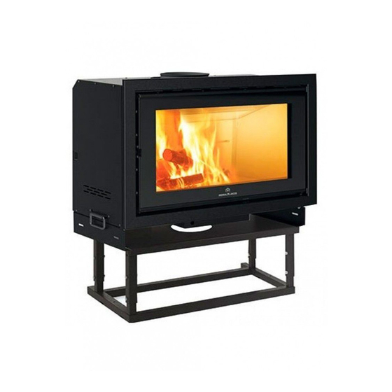
SCREEN EVO 80
Installation, use and maintenance manual
EdilKamin SCREEN EVO 80 Installation, Use And Maintenance Manual
Hide thumbs
1
Table Of Contents
2
3
4
5
6
7
8
9
10
11
12
13
14
15
16
17
18
19
20
21
22
23
24
25
26
27
28
page
of
28
Go
/
28
Contents
Table of Contents
Bookmarks
Advertisement
Table of Contents
1
Table of Contents
2
Introduction
3
Safety Information
4
Technical Data
5
Dimensions
6
Preparation and Packaging
7
Installation
8
Instructions for Use
9
Maintenance
10
In the Event of Problems
Download this manual
SCREEN EVO 80-100
WOOD FIREPLACE
UK
Installation, use and maintenance
Table of
Contents
Previous
Page
Next
Page
1
2
3
4
5
Advertisement
Table of Contents
Need help?
Do you have a question about the SCREEN EVO 80 and is the answer not in the manual?
Ask a question
Questions and answers
Related Manuals for EdilKamin SCREEN EVO 80
Indoor Fireplace EdilKamin SCREEN EVO 100 Installation, Use And Maintenance Manual
(28 pages)
Indoor Fireplace EdilKamin BASIC Installation, Use And Maintenance Manual
(146 pages)
Indoor Fireplace EdilKamin SCREEN 80 Installation, Use And Maintenance Manual
(90 pages)
Indoor Fireplace EdilKamin CRISTAL Series Installation, Use And Maintenance Manual
(18 pages)
Indoor Fireplace EdilKamin INPELLET 54 Installation, Use And Maintenance Manual
(108 pages)
Indoor Fireplace EdilKamin IDRO 50 Installation, Use And Maintenance Manual
(29 pages)
Indoor Fireplace EDILKAMIN Point Plus Installation, Use And Maintenance Manual
(169 pages)
Indoor Fireplace EdilKamin FORTE PLUS Installation, Use And Maintenance Manual
(65 pages)
Indoor Fireplace EdilKamin Firebox Deco Series Installation, Use And Maintenance Manual
(80 pages)
Indoor Fireplace EdilKamin PELLKAMIN 8 EVO Manual
(64 pages)
Indoor Fireplace EdilKamin ACQUATONDO 22 ROUND Installation, Use And Maintenance Manual
(94 pages)
Indoor Fireplace EdilKamin PELLINSERT 54 Installation, Use And Maintenance Manual
(101 pages)
Indoor Fireplace EdilKamin TINY Installation, Use And Maintenance Manual
(208 pages)
Indoor Fireplace EdilKamin SOLEIL plus Installation, Use And Maintenance Manual
(169 pages)
Indoor Fireplace EdilKamin INPELLET 49 Installation, Use And Maintenance Manual
(120 pages)
Indoor Fireplace EdilKamin WINDO2 75 Installation, Use And Maintenance Manual
(20 pages)
This manual is also suitable for:
Screen evo 100
Table of Contents
Print
Rename the bookmark
Delete bookmark?
Delete from my manuals?
Login
Sign In
OR
Sign in with Facebook
Sign in with Google
Upload manual
Upload from disk
Upload from URL


Need help?
Do you have a question about the SCREEN EVO 80 and is the answer not in the manual?
Questions and answers