EdilKamin IDROPELLBOX Installation, Use And Maintenance Manual
Wood pellet boiler-fireplace
Hide thumbs
Also See for IDROPELLBOX:
- Installation, use and maintenance manual (127 pages) ,
- Installation, use and maintenance manual (126 pages) ,
- Installation, use and maintenance manual (211 pages)

Related Manuals for EdilKamin IDROPELLBOX


Summary of Contents for EdilKamin IDROPELLBOX
- Page 1 IDROPELLBOX WOOD PELLET BOILER-FIREPLACE Installation, use and maintenance pag. 2...
-
Page 2: Table Of Contents
Maintenance Troubleshooting The original language of this manual is Italian The undersigned EDILKAMIN S.p.A., with registered office in Via Vincenzo Monti 47 - 20123 Milan (Italy) - Tax ID Code and VAT number 00192220192 Hereby declares, under its sole responsibility, that:... -
Page 3: Introduction And Readers Of This Manual
Commissioning is required for activation of the Edilkamin The diagrams provided in this manual are for illustration manufacturer warranty. The warranty is only valid in the purposes only: they do not always strictly refer to your country where the product was bought. -
Page 4: Safety Information
DO NOT product: specifically, neither Edilkamin nor PLACE LAUNDRY ON THE APPLIANCE. the retailer are liable for damage resulting DO NOT PLACE DRYING RACKS WITHIN from incorrect installation or maintenance. -
Page 5: Dimensions
DIMENSIONS * minimum support height Combustion air Ø 40 mm Smoke outlet Ø 80 mm HYDRAULIC CONNECTIONS Drain 3/4” male System in 3/4” male System return 3/4” male VSP: Safety valve 3/4” female Fill/Top up 3/4” male USER/INSTALLER... - Page 6 ELECTRONIC EQUIPMENT ELECTRONIC CIRCUIT BOARD Optional Water boiler outlet Thermocouple T° smoke probe probe Flow sensor Panel control RPM smoke Vacuum gauge RS232 socket Screw 1 Vacuum gauge Reading points consolle Thermocouple Screw 2 not to be used battery CR 2032 Heat recovery ventilation FUSE 2A...
-
Page 7: Technical Data
Protection on electronic circuit board Fuse 2AT, 250 Vac 5x20 The above data is for guidance only and was measured during certification by a notified body. EDILKAMIN s.p.a. reserves the right to modify the product without notification in the interests of improvement. USER/INSTALLER... -
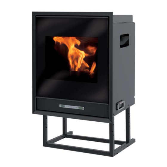
Page 8: Features
FEATURES PRINCIPLE OF OPERATION Small pellet-burning boiler-fireplace that is able to heat water to power heating systems (radiators, heated towel rails, underfloor heating panels) also with heat recovery in the room where it is installed via the release of a mo- derate amount of hot air (I). - Page 9 COMPONENTS - SAFETY AND DETECTION DEVICES Water overheating safety thermostat with Overpressure valve upon reaching the pressure stipulated on the plate, the manual reset system is triggered to discharge the water and conse- measures the temperature of the water inside the boiler- quently the water must be topped up.
-
Page 10: Installation
INSTALLATION (Reserved for DEALER) IDROPELLBOX MUST NEVER BE MADE TO OPERATE WITHOUT WATER IN THE SYSTEM. MUST BE MADE WITH A PRESSURE OF ABOUT 1.5 BAR. IT CAN BE DAMAGED IF IT IS IGNITED WITH NO WATER IN THE SYSTEM. - Page 11 Safety valve ACCESSORIES: In the diagrams referred to in the previous pages the use of accessories available from the Edilkamin catalogue has been assumed. Individual spare parts are also available (exchanger, valves, etc). For information, please contact your local dealer.
- Page 12 An inadequate earthing system can cause anomalies for If the smoke channel is fitted inside a chimney flue, the which Edilkamin cannot be held liable. latter must be suitable for solid fuel. If it is wider than 150 mm in diameter it must be improved...
- Page 13 • Rather, at least 1 cm. (approx.) space must be left to • If using a prefabricated Edilkamin covering, In order to allow air to flow, thereby preventing heat from accumula- define the exact position of the IDROPELLBOX, it is im- ting. The counter-hood can be created from fireproof pla- portant sterboard panels or plaster sheets.
-
Page 14: Introduction About Use
INSTRUCTIONS FOR USE Before igniting. The first start up must, without fail, be performed by DEALER. You must consult the DEALER in your area when igniting the boiler-fireplace for the first time, in order for the boiler-fireplace to be calibrated according to the type of pellets and installation conditions The DEALER must also: - Verify that the hydraulic system is correctly installed... - Page 15 INSTRUCTIONS FOR USE Mimic panel to turn on and off (hold down for 2”) and to exit from the menu during programming to access the menu during programming to increase the various settings to decrease the various settings (pellet loading/reserve button) press once to ‘inform’...
- Page 16 MENU to confirm. Should this correction not suffice, contact In the same way, adjust the shutdown times. the Edilkamin-authorised Dealer, to esta- The program is confirmed by pressing the MENU button when “Saved” appears on the display.
- Page 17 PUMP PUMP SPECIFICATIONS USER...
- Page 18 PUMP: INSTALLATION AND OPERATING INSTRUCTIONS CONTROL MODES AND FUNCTIONS Variable differential pressure ∆p-v (I, II, III) Recommended for two-pipe heating systems with radiators to reduce the flow noise at thermostatic valves. The pump reduces the delivery head to half in the case of decreasing volume flow in the pipe network.
- Page 19 PUMP: INSTALLATION AND OPERATING INSTRUCTIONS VENTING Activate the pump venting function via the operating button: press and hold for 3 seconds, then release. •The pump venting function is initiated and lasts 10 minutes. •The top and bottom LED rows flash in turn at 1 second intervals.
- Page 20 PUMP: INSTALLATION AND OPERATING INSTRUCTIONS Press the BUTTON LED display Control mode Pump curve Constant speed Constant speed Variable differential pressure ∆p-v Variable differential pressure ∆p-v Variable differential pressure ∆p-v Constant differential pressure ∆p-c Constant differential pressure ∆p-c Constant differential pressure ∆p-c Constant speed Pressing the button for the 9th time returns to the factory setting (constant speed / pump...
- Page 21 PUMP: INSTALLATION AND OPERATING INSTRUCTIONS Lock/unlock the button To activate the key lock, press and hold the operating button for 8 seconds until the LEDs for the selected setting briefly flash, then release. •LEDs flash constantly at 1-second intervals. •The key lock is activated: pump settings can no longer be changed.
- Page 22 PUMP: INSTALLATION AND OPERATING INSTRUCTIONS FAULT SIGNALS • The fault signal LED indicates a fault. • The pump switches off (depending on the fault) and attempts a cyclical restart. FAULTS CAUSES REMEDY Blocking Rotor blocked Activate manual restart or Lights up red contact customer service Contacting/ winding Winding defective...
- Page 23 INSTRUCTIONS FOR USE REMOTE CONTROL Key to buttons and display: This controls all the functions. It is necessary to point it : ignition / shutdown button directly at the boiler-fireplace. +/- : to increase/decrease the various regulations For further information contact our customer service : button to switch to the “EASY TIMER ”...
-
Page 24: Maintenance
MAINTENANCE Before performing any maintenance, disconnect the appliance from the mains. Remember to vacuum the combustion chamber before each ignition Should ignition fail, do not re-ignite until you have emptied the combustion chamber Attention: the pellet emptied from the combustion chamber mustnotbe deposited inside the hopper. Regular maintenance is required for the boiler-fireplace to function correctly. - Page 25 For any spare parts, contact your dealer or technician. flue every 3 months. Using non-original spare parts may damage the appliance and relieves Edilkamin of all liability for You should clean the chimney system at least once a damage resulting such use.
-
Page 26: Troubleshooting
TROUBLESHOOTING n the event of problems the boiler-fireplace stops automatically and runs the shutdown pro- cess and the display shows text regarding the motivation of the shutdown (see the various alarms below). Never pull the plug during shutdown on account of malfunction. To start the boiler-fireplace up again after a shutdown, let the shutdown procedure end (10 minutes marked by a beep) tand then press the button 0/1. - Page 27 TROUBLESHOOTING 8 ) Signalling: H2O TEMPALARM Problem: Shuts down due to water temperature being higher than 90 °C. An excessive temperature may occur because of the following: • system too small: ask the DEALER to activate the ECO function • blockage: clean the exchanger pipes, the combustion chamber and the smoke outlet. 9) Signalling: Verific./air flow: (intervenes if the flow sensor detects insufficient combustion ).
- Page 28 *674760-GB* w w w . e d i l k a m i n . c o m cod. 674760-GB .01.19/N...
Need help?
Do you have a question about the IDROPELLBOX and is the answer not in the manual?
Questions and answers