
Related Manuals for Johnson Controls VRF System


Summary of Contents for Johnson Controls VRF System
- Page 1 ENGINEERING MANUAL INVERTER-DRIVEN MULTI-SPLIT SYSTEM HEAT PUMP AIR CONDITIONERS Technical Catalog for Outdoor Unit Engineering Manual < Indoor Units > ● 2-Way Cassette Type (H,Y,C)IC2018B21S (H,Y,C)IC2024B21S TC-16002...
-
Page 3: Important Safety Instructions
IMPORTANT NOTICE AND SAFETY SUMMARY 1. Introduction This Engineering Manual concentrates on heat pump air conditioning units. Read this manual carefully before performing installations or operations. This manual should be considered as a permanent part of the air conditioning equipment and should remain with the air conditioning equipment. (Transportation/Installation Work) > (Refrigerant Piping Work) > (Electrical Wiring Work) > (Ref. Charge Work) > (Test Run) > (User) 2. Important Safety Instructions Signal Words Indicates a hazardous situation that, if not avoided, could result in death or serious injury. Indicates a hazardous situation that, if not avoided, could result in minor or moderate injury. Indicates information considered important, but not hazard-related (for example, messages relating to property damage). General Precautions To reduce the risk of serious injury or death, read these instructions thoroughly and follow all warnings or cautions included in all manuals that accompanied the product and are attached to the unit. Refer back to these instructions as needed. ● This system should be installed by personnel certified by Johnson Controls, Inc. Personnel must be qualified according to local, state and national building and safety codes and regulations. Incorrect installation could cause leaks, electric shock, fire or explosion. In areas where Seismic ‘’Performance requirements are specified, the appropriate measures should be taken during installation to guard against possible damage or injury that might occur in an earthquake if the unit is not installed correctly, injuries may occur due to a falling unit. ● Use appropriate Personal Protective Equipment (PPE), such as gloves and protective goggles and, where appropriate, have a gas mask nearby. Also use electrical protection equipment and tools suited for electrical operation purposes. Keep a quenching cloth and a fire extinguisher nearby during brazing. Use care in handling, rigging, and setting of bulky equipment. - Page 4 Take the following precautions to reduce the risk of property damage. ● Be careful that moisture, dust, or variant refrigerant compounds not enter the refrigerant cycle during installation work. Foreign matter could damage internal components or cause blockages. ● If air filters are required on this unit, do not operate the unit without the air filter set in place. If the air filter is not installed, dust may accumulate and breakdown may result. ● Do not install this unit in any place where silicon gases can coalesce. If the silicon gas molecules attach themselves to the surface of the heat exchanger, the finned surfaces will repel water. As a result, any amount of drainage moisture condensate can overflow from the drain condensate pan and could run inside of the electrical box, possibly causing electrical failures. ● When installing the unit in a hospital or other facility where electromagnetic waves are generated from nearby medical and/or electronic devices, be prepared for noise and electronic interference Electromagnetic Interference (EMI). Do not install where the waves can directly radiate into the electrical box, controller cable, or controller. Inverters, appliances, high-frequency medical equipment, and radio communications equipment may cause the unit to malfunction. The operation of the unit may also adversely affect these same devices. Install the unit at least 10 ft. (approximately 3m) away from such devices. ● When a wireless controller is used, locate at a distance of at least 3.3 ft. (approximately 1m) between the indoor unit and electric lighting. If not, the receiver part of the unit may have difficulty receiving operation commands. ● Do not install the unit in any location where animals and plants can come into direct contact with the outlet air stream. Exposure could adversely affect the animals and plants. ● Do not install the unit with any downward slope to the side of the drain boss. If you do, you may have drain water flowing back which may cause leaks. ● Be sure the drain hose discharges water properly. If connected incorrectly, it may cause leaks. ● Do not install the unit in any place where oil can seep onto the units, such as table or seating areas in restaurants, and so forth. For these locations or social venues, use specialized units with oil-resistant features built into them. In addition, use a specialized ceiling fan designed for restaurant use. These specialized oil-resistant units can be ordered for such applications. However, in places where large quantities of oil can splash onto the unit, such as a factory, even the specialized units cannot be used. These products should not be installed in such locations. ● If the wired controller is installed in a location where electromagnetic radiation is generated, make sure that the wired controller is shielded and cables are sleeved inside conduit tubing.
-
Page 5: Installation Precautions
Installation Precautions To reduce the risk of serious injury or death, the following installation precautions must be followed. ● When installing the unit into… ◦ A wall: Make sure the wall is strong enough to hold the unit’s weight. It may be necessary to construct a strong wood or metal frame to provide added support. ◦ A room: Properly insulate any refrigerant tubing run inside a room to prevent “sweating” that can cause dripping and water damage to wall and floors. ◦ Damp or uneven areas: Use a raised concrete pad or concrete blocks to provide a solid, level foundation for the unit to prevent water damage and abnormal vibration. ◦ An area with high winds: Securely anchor the outdoor unit down with bolts and a metal frame. Provide a suitable air baffle. ◦ A snowy area (only for Heat Pump Model): Install the outdoor unit on a raised platform that is higher than drifting snow. Provide snow vents. ● If the remote sensors are not used with this controller, then do not install this controller… ◦ in a room where there is no thermostat. ◦ where the unit is exposed to direct sunshine or direct light. ◦ where the unit will be in close proximity to a heat source. ◦ where hot/cold air from the outdoors, or a draft from elsewhere (such as air vents, diffusers or grilles) can affect air circulation. ◦ in areas with poor air circulation and ventilation. ● Do not install the unit in the following places. Doing so can result in an explosion, fire, deformation, corrosion, or product failure. ◦ Explosive or flammable atmosphere. ◦ Where fire, oil, steam, or powder can directly enter the unit, such as in close proximity or directly above a kitchen stove. -
Page 6: Refrigerant Precautions
Refrigerant Precautions To reduce the risk of serious injury or death, the following refrigerant precautions must be followed. ● As originally manufactured, this unit contains refrigerant installed by Johnson Controls. Johnson Controls uses only refrigerants that have been approved for use in the unit’s intended home country or market. Johnson Controls distributors similarly are only authorized to provide refrigerants that have been approved for use in the countries or markets they serve. The refrigerant used in this unit is identified on the unit’s faceplate and/or in the associated manuals. Any additions of refrigerant into this unit must comply with the country’s requirements with regard to refrigerant use and should be obtained from Johnson Controls distributors. Use of any non-approved refrigerant substitutes will void the warranty and will increase the potential risk of injury or death. ● If installed in a small room, take measures to prevent the refrigerant from exceeding the maximum allowable concentration in the event that refrigerant gases should escape. Refrigerant gases can cause asphyxiation (0.026 lbs/ft (0.42 kg/m ) based on ISO 5149 for R410A). Consult with your distributor for countermeasures (ventilation system and so on). If refrigerant gas has leaked during the installation work, ventilate the room immediately. ● Check the design pressure for this product is 601 psi (4.15MPa). The pressure of the refrigerant R410A is 1.4 times higher than that of the refrigerant R22. Therefore, the refrigerant piping for R410A shall be thicker than that for R22. Make sure to use the specified refrigerant piping. If not, the refrigerant piping may rapture due to an excessive refrigerant pressure. Besides, pay attention to the piping thickness when using copper refrigerant piping. The thickness of copper refrigerant piping differs depending on its material. ● The refrigerant R410A is adopted. The refrigerant oil tends to be affected by foreign matters such as moisture, oxide film, (or fat). Perform the installation work with care to prevent moisture, dust, or different refrigerant from entering the refrigerant cycle. Foreign matter can be introduced into the cycle from such parts as expansion valve and the operation may be unavailable. ● To avoid the possibility of different refrigerant or refrigerant oil being introduced into the cycle, the sizes of the charging connections have been changed from R407C type and R22 type. It is necessary to prepare the appropriate tools before performing installation work. ● Use refrigerant pipes and joints which are approved for use with R410A. ● A compressor/unit comprises a pressurized system. Never loosen threaded joints while the system is under pressure and never open pressurized system parts. - Page 7 Electrical Precautions Take the following precautions to reduce the risk of electric shock, fire or explosion resulting in serious injury or death. ● Highly dangerous electrical voltages are used in this system. Carefully refer to the wiring diagram and these instructions when wiring. Improper connections and inadequate grounding can cause serious injury or death. ● Perform all electrical work in strict accordance with this installation and maintenance manual and all the relevant regulatory standards. ● Before servicing, open and tag all disconnect switches. Never assume electrical power is disconnected. Check with meter and equipment. ● Only use electrical protection equipment and tools suited for this installation. ● Insulate a wired controller against moisture and temperature extremes. ● Use specified cables between units. ● The new air conditioner may not function normally in the following instances: ◦ If electrical power for the new air conditioner is supplied from the same transformer as the device* referred to below. ◦ If the power source cables for this device* and the new air conditioner unit are located in close proximity to each other. Device*: (Example): A lift, container crane, rectifier for electric railway, inverter power device, arc furnace, electric furnace, large-sized induction motor and large-sized switch. Regarding the cases mentioned above, surge voltage may be inducted into the power supply cables for the packaged air conditioner due to a rapid change in power consumption of the device and an activation of a switch. Check field regulations and standards before performing electrical work in order to protect the power supply for the new air conditioner unit. ● Communication cabling shall be a minimum of AWG18 (0.82mm ), 2-Conductor, Stranded Copper. Shielded cable must be considered for applications and routing in areas of high EMI and other sources of potentially excessive electrical noise to reduce the potential for communication errors. When shielded cabling is applied, proper bonding and termination of the cable shield is required as per Johnson Controls guidelines. Plenum and riser ratings for communication cables must be considered per application and local code requirements.
-
Page 8: Table Of Contents
- CONTENTS - IMPORTANT NOTICE AND SAFETY SUMMARY ..................i 1. Introduction ..............................i 2. Important Safety Instructions ........................i 1. General Information (Features) ........................1-1 2. 2-Way Cassette Type ..........................2-1 2.1 Unit Nomenclature ..........................2-1 2.2 Line-up .............................. 2-1 2.3 General Data ............................. 2-2 2.4 Dimensional Data ..........................2-3 2.5 Structure ............................2-4 2.6 Component Data .......................... -
Page 9: General Information (Features)
1. General Information (Features) VRF Air Conditioners Johnson Controls proudly introduces new Variable Refrigerant Flow (VRF) air conditioners, a highly-efficient and reliable air-conditioning system. Recently, increased numbers of buildings are requiring "Intelligent" facilities that include communication networks, office automation, and a comfortable environment. In particular, a comfortable environment is becoming more of a year-around requirement in office buildings. - Page 10 FEATURES ● Improvement of Energy-Saving (1) Adopting High Efficient New Turbo Fan and DC Fan Motor (2) Improvement of Heat Exchanger and Reduction of Airflow Loss Turbo Fan Improved Heat Exchanger Optimized for excellent efficiency. Improved Airflow Path with Smooth Air Inlet Energy-Efficient Fan Motor (3) Improvement of Energy-Saving Operation by Adopting Motion Sensor * Adopting Motion Sensor Function...
- Page 11 FEATURES ● Automatic COOL/HEAT Operation By improving differential temperature for automatic COOL/HEAT operation, it is possible to perform refined and sensitive operation and a more comfortable air conditioned environment is realized. Control Flow of AUTO Mode SET TEMP. +3 F (2 SET TEMP.
-
Page 13: Way Cassette Type
2-WAY CASSETTE 2. 2-Way Cassette Type 2.1 Unit Nomenclature Model Descriptions Example Nomenclature Description H = Hitachi Brand Y = York Brand C = Coleman Brand Indoor Unit Indoor Unit Type C2 = 2-Way Cassette Type Capacity (MBH) Refrigerant Type B = R410A Power Supply 2 = 208/230Volts - 1Phase - 60Hz... -
Page 14: General Data
27-15/16 (710) Net Weight lbs. (kg) 16.5 (7.5) NOTES: *1: Nominal capacity is based on combinations within the VRF system and the following conditions: Cooling Operation Conditions Indoor Air Inlet Temperature: 80°F DB (26.7°C DB) 67°F WB (19.4°C WB) Outdoor Air Inlet Temperature: 95°F DB (35.0°C DB) -
Page 15: Dimensional Data
2-WAY CASSETTE 2.4 Dimensional Data Models: (H,Y,C)IC2018B21S and (H,Y,C)IC2024B21S with Decorative Panel P-AP90DNA Unit: inch (mm) Min. 94-1/2 (2400) TC-16002-rev.1... -
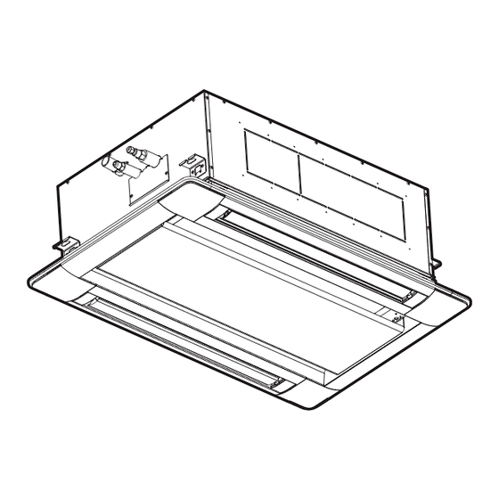
Page 16: Structure
2-WAY CASSETTE 2.5 Structure Unit: inch (mm) Part Name Remarks Fan Motor Heat Exchanger Distributor Strainer Electronic Expansion Valve Electrical Control Box Refrigerant Gas Pipe Connection with f5/8 (15.88) Flare Nut Refrigerant Liquid Pipe Connection with f3/8 (9.52) Flare Nut Condensate Pipe Connection VP25 (OD f1-1/4 (32)) Drain-up Mechanism... -
Page 17: Component Data
2-WAY CASSETTE 2.6 Component Data Indoor Heat Exchanger and Fan Model (H,Y,C)IC2018B21S (H,Y,C)IC2024B21S Heat Exchanger Type Multi-Pass Cross Finned Tube Tube Material Copper Tube Outer Diameter 1/4 (7) 1/4 (7) in. (mm) Rows Number of Tube/Coil Fin Material Aluminum Pitch in. -
Page 18: Operation Space
Model SHF * (H,Y,C)IC2018B21S 0.771 (H,Y,C)IC2024B21S 0.772 NOTE: * SHF is based on combinations within the VRF system and the following conditions: Cooling Operation Conditions Indoor Air Inlet Temperature: F DB (26.7 C DB) F WB (19.4 C WB) Outdoor Air Inlet Temperature: 95 F DB (35.0... -
Page 19: Electrical Data
2-WAY CASSETTE 2.9 Electrical Data Indoor Unit Main Power Applicable Voltage Power Supply Unit Fan Motor Model Maximum Minimum (H,Y,C)IC2018B21S 0.057 208/230 (H,Y,C)IC2024B21S 0.057 VOL: Rated Unit Power Supply Voltage (V) Phase Frequency (Hz) MCA: Minimum Circuit Ampacity (A) MFA: Maximum Fuse Ampacity (A) OPT: Rated Motor Output (kW) FLA: Full Load Ampacity (A) NOTE:... -
Page 20: Sound Data
2-WAY CASSETTE 2.10 Sound Data Model: (H,Y,C) IC2018B21S Model: (H,Y,C) IC2024B21S NOTE: Operation sound is equivalent to an anechoic chamber (free space). Noise level will be increased by the surrounding noise and echoes. TC-16002-rev.1... -
Page 21: Control System
2-WAY CASSETTE 2.11 Control System 2.11.1 Refrigerant System Models: (H,Y,C)IC2018B21S and (H,Y,C)IC2024B21S Mark Part Name Heat Exchanger Distributor Strainer Electronic Expansion Valve Unit: inch (mm) (A) Gas Pipe (B) Liquid Pipe Model Distributor (C) (OD×T) (D) (OD×T) Connection Connection (H,Y,C)IC2018B21S f5/8 f3/8 f5/8×t0.039... -
Page 22: Standard Operation Sequence
2-WAY CASSETTE 2.11.2 Standard Operation Sequence ■ Cooling Operation The sequence may be different depending on the outdoor unit model to be connected. Refer to the “Outdoor Unit Engineering Manual” for details. ■ Dry Operation The sequence may be different depending on the outdoor unit model to be connected. Refer to the “Outdoor Unit Engineering Manual”... - Page 23 2-WAY CASSETTE ■ Freeze Protection Control during Cooling or Dry Operation I.U.: Indoor Unit Power Supply MIF : Motor for Indoor Fan Cooling or Dry Operation Is compressor running for more than 15 min. *1): The check interval differs depending on the conditions. Cooling or Dry Operation Gas or Liquid Pipe >...
- Page 24 2-WAY CASSETTE ■ Prevention Control for Excessively High Outlet Air Temperature (High Outlet Air Temperature Heat Lockout) I.U.: Indoor Unit Heating Operation I.U. Air < 149 F(65 Outlet Temp. > 149 F(65 Thermo-OFF Elapsed Time: 3 min. I.U. Air > 149 F(65 Outlet Temp.
- Page 25 2-WAY CASSETTE ■ Control for Motion Sensor (with Decorative Panel P-AP90DNA) Motion Sensor : OFF Operation: OFF Operation Stop Operation Start Normal Operation When the wired controller is set to one of the When the wired controller is set to one of the following or at Test Run Mode.
-
Page 26: Safety And Control Device Setting
2-WAY CASSETTE 2.11.3 Safety and Control Device Setting Model (H,Y,C)IC2018B21S, (H,Y,C)IC2024B21S For Evaporator Fan Motor Automatic Reset, Non-Adjustable Internal Thermostat Cut-Out (100 For Control Circuit Fuse Capacity Freeze Protection Thermostat Cut-Out 32 (0) Cut-In 57.2 (14) Thermostat Differential 35.6 (2) 2-14 TC-16002-rev.1... -
Page 27: Wiring Diagram
2-WAY CASSETTE 2.11.4 Wiring Diagram Models: (H,Y,C)IC2018B21S and (H,Y,C)IC2024B21S with Decorative Panel P-AP90DNA Ground Wiring Mark Name Optional Connector (For Signal Input) CN7, 8 Optional Connector (For Signal Output) CN10 Optional Connector (For Motion Sensor) DSW3, 4, 7, 9, DIP Switch for Setting EFR1, EFS1 Fuse Motor for Indoor Fan... -
Page 29: Optional Parts
OPTIONAL PARTS 3. Optional Parts 3.1 Line Up Optional Parts Item No. Optional Parts Model Name Motion Sensor Kit SOR-NED Antibacterial Long Life Air Filter F-90MD-K1 Filter Box B-90HD Duct Adapter PD-150D Infrared (IR) Receiver Kit C2IRK01 3P Connector Cable PCC-1A Remote Sensor THM-R2A... -
Page 30: Motion Sensor Kit: Sor-Ned
OPTIONAL PARTS 3.2 Motion Sensor Kit: SOR-NED Unit: inch (mm) Dimensional Data 5-5/16 (135.4) 3-3/16 (81) Connecting Cable (CN10) (to Electrical Control Box of Indoor Unit) Installation State 3-3/16 (50.5) (81) Motion Sensor Kit (SOR-NED) 43-5/16 (1100) TC-16002-rev.1... - Page 31 OPTIONAL PARTS Installation ● Do not run the connecting cable for the motion sensor kit and the power source cable in parallel. It may cause malfunction of the motion sensor kit because of electromagnetic interference. ● When the motion sensor kit is mounted with the indoor unit’s installation, start from procedure ●...
- Page 32 OPTIONAL PARTS Connect the cable to the CN10 (1) Open the electrical box cover at the indoor unit. Connect the connecting cable to CN10 of the PCB in the electrical box. Electrical Box Connector (CN10) 5P (Red) (2) After connecting the connecting cable to each terminal, run it out to the false ceiling or outside of the unit.
- Page 33 OPTIONAL PARTS Attachment of Motion Sensor Kit (1) Run the connecting cable out from the corner pocket of the decorative panel. Connect the wiring for the motion sensor kit to the relay connector as in the following figure. After connecting, cover the relay connector connection with the wiring cover, and secure the wiring cover with the plastic bands.
-
Page 34: Antibacterial Long Life Air Filter: F-90Md-K1
OPTIONAL PARTS 3.3 Antibacterial Long Life Air Filter: F-90MD-K1 Unit: inch (mm) Dimensional Data Installation State 32-1/16 (814) 24-13/16 (630) Paper Indoor Unit Frame Antibacterial Filter Long Life Air Filter Media Filter Box (Option) 2-11/16 (68) Ceiling Air Inlet Installation Flat Grille 1-9/16 Height... -
Page 35: Filter Box: B-90Hd
OPTIONAL PARTS 3.4 Filter Box: B-90HD Unit: inch (mm) Dimensional Data Filter Holder (Resin) Packing 2-3/8 (60) 9/16 (15) (Before Compression) Galvanized Sheet Metal 5/16 (8) (After Compression) 33-7/16 (850) 2-11/16 (68) (Installation Height) Installation State 24-13/16 (630) Indoor Unit Air Filter 2-11/16 (68) Installation... -
Page 36: Duct Adapter: Pd-150D
OPTIONAL PARTS 3.5 Duct Adapter: PD-150D Unit: inch (mm) Dimensional Data Duct Adapter 1-3/8 (35) 2-3/4 (70) φ1/4 (6.5) x 4 Guide 3/16t (5t) Polyethylene Installation State 24-13/16 (630) Duct Band Fresh Air 12-3/8 (315) Duct Adapter Intake Duct Adapter Fresh Screw x 4 Indoor Unit... -
Page 37: Infrared (Ir) Receiver Kit: C2Irk01
OPTIONAL PARTS 3.6 Infrared (IR) Receiver Kit: C2IRK01 C2IRK01 is only available to be used in combination with the wireless controller CIR01 and the indoor unit 2-way cassette type models. Factory-Supplied Accessories Check to ensure that the following accessories are packed with the IR receiver kit. Accessory Qty. - Page 38 OPTIONAL PARTS Connect the accessory connecting cable to the terminal block. Open the electrical box cover of the indoor unit. Attach the connecting cable to terminals A and B in the Terminal Block for electrical box. (There is no polarity with terminals A and B.) Controller Connecting Cable...
- Page 39 OPTIONAL PARTS (2) While pushing the wiring into the corner pocket, insert two coupling hooks at A to the square hole of the decorative panel, and push the IR receiver kit in the direction of the arrow ( A ) shown at the far right.
- Page 40 OPTIONAL PARTS Optional Functions Turn OFF the power supply completely before setting the DIP switch for the IR receiver kit. Not turning off the power may cause an electric shock. The following switches are on the IR receiver kit. 1 2 3 4 5 6 Remove DIP Switch (DSW1) TIMER...
- Page 41 OPTIONAL PARTS Identifying Indoor Units Installed for a Side-by-Side Operation Turn OFF the power supply completely before setting the DIP switch for the IR receiver kit. Not doing so may cause an electric shock. "Identified" Indoor Unit When two indoor units are installed side by side, the Indoor Indoor Unit A...
- Page 42 OPTIONAL PARTS [ Electrical Wiring Connecting and Setting ] Connection between Indoor Units Perform the connection work as shown below. Power Supply Cable 208/230V Indoor Unit No.1 Indoor Unit No.2 Indoor Unit No.3 – A B 1 2 – A B 1 2 –...
- Page 43 OPTIONAL PARTS Test Run for Wireless Controller (CIR01) After all installations are completed, a test run should be performed. (1) Perform the test run according to the installation manual for the wireless controller. (2) The test run for the wireless controller will take two hours to complete. If the TIMER indicator (green) is flashing (0.5 second ON/0.5 second OFF) after two hours, an alarm may occur.
-
Page 44: Connector Cable: Pcc-1A
OPTIONAL PARTS 3.7 3P Connector Cable: PCC-1A This accessory connector is utilized to provide remote start/stop capability (binary input) to an indoor unit and provide operating status (binary output) of an indoor unit's functions. (System Parts: One set contains five 3P cords.) Connector (“XARP-03V”... -
Page 45: Relay And 3 Pin Connector Kit: Psc-5Ra
OPTIONAL PARTS 3.9 Relay and 3 Pin Connector Kit: PSC-5RA This relay kit provides for basic input/output integration functionality (indoor unit ON/OFF, operating mode, alarm status) to third party controllers and Building Management Systems (BMS). Unit: inch (mm) Max. 4-1/2 (115) 4 (101) 5/16 5/16... -
Page 47: Selection Data
SELECTION DATA 4. Selection Data 4.1 Selection Guide Refer to the Engineering Manual for the Outdoor Unit. 4.2 Capacity Table 4.2.1 Cooling Capacity ■ 2-Way Cassette: (H,Y,C)IC2018B21S and (H,Y,C)IC2024B21S Indoor Air Temp Indoor F WB) Unit Model Outdoor Air (MBH) (MBH) (MBH) (MBH) -
Page 48: Heating Capacity
SELECTION DATA 4.2.2 Heating Capacity ■ 2-Way Cassette: (H,Y,C)IC2018B21S and (H,Y,C)IC2024B21S Indoor Air Temp Indoor F DB) Unit Model Outdoor Air (MBH) (MBH) (MBH) (MBH) (MBH) (MBH) Temp ( F WB) 14.1 14.1 14.2 14.2 14.0 13.9 14.9 14.9 14.9 14.9 14.7 14.5... - Page 50 © 2016 Johnson Controls, Inc. TC-16002-rev.1 Code No. LIT-12012262 Revised February 2018...
Need help?
Do you have a question about the VRF System and is the answer not in the manual?
Questions and answers