Table of Contents
Advertisement
Quick Links
INSTALLATION
MANUAL
CONTENTS
GENERAL . . . . . . . . . . . . . . . . . . . . . . . . . . . . . . . . 4
SAFETY CONSIDERATIONS . . . . . . . . . . . . . . . . . 4
INSPECTION. . . . . . . . . . . . . . . . . . . . . . . . . . . . . . 4
REFERENCE. . . . . . . . . . . . . . . . . . . . . . . . . . . . . . 5
RENEWAL PARTS . . . . . . . . . . . . . . . . . . . . . . . . . 5
APPROVALS . . . . . . . . . . . . . . . . . . . . . . . . . . . . . 5
PRODUCT NOMENCLATURE . . . . . . . . . . . . . . . . 6
INSTALLATION . . . . . . . . . . . . . . . . . . . . . . . . . . . 7
OPERATION . . . . . . . . . . . . . . . . . . . . . . . . . . . . . 42
START-UP (COOLING) . . . . . . . . . . . . . . . . . . . . 48
START-UP (GAS HEAT). . . . . . . . . . . . . . . . . . . . 49
TROUBLESHOOTING . . . . . . . . . . . . . . . . . . . . . 52
SEE THE FOLLOWING PAGE FOR A COMPLETE TABLE OF CONTENTS.
NOTES, CAUTIONS AND WARNINGS
The installer should pay particular attention to the words:
NOTE, CAUTION, and WARNING. Notes are intended to
clarify or make the installation easier. Cautions are given
to prevent equipment damage. Warnings are given to
alert installer that personal injury and/or equipment dam-
age may result if installation procedure is not handled
properly.
CAUTION:
READ ALL SAFETY GUIDES BEFORE YOU
BEGIN TO INSTALL YOUR UNIT.
SAVE THIS MANUAL
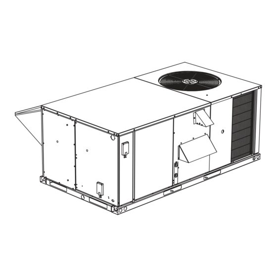
SUNLINE MAGNUM™
GAS/ELECTRIC SINGLE PACKAGE
AIR CONDITIONERS
DJ 036, 048 & 060
362246-YIM-A-0208
Advertisement
Table of Contents
Troubleshooting

Related Manuals for Johnson Controls SUNLINE MAGNUM DJ 036


Summary of Contents for Johnson Controls SUNLINE MAGNUM DJ 036
- Page 1 INSTALLATION SUNLINE MAGNUM™ MANUAL GAS/ELECTRIC SINGLE PACKAGE AIR CONDITIONERS CONTENTS DJ 036, 048 & 060 GENERAL ....... . 4 SAFETY CONSIDERATIONS .
-
Page 2: Table Of Contents
HIGH-PRESSURE LIMIT SWITCH ....43 UNIT FLASH CODES......61 Johnson Controls Unitary Products... - Page 3 UNIT CONTROL BOARD FLASH CODES ..61 BELT DRIVE) - SIDE DUCT APPLICATION ..36 IGNITION CONTROL BOARD FLASH CODES ..61 Johnson Controls Unitary Products...
-
Page 4: General
Wear safety glasses and work gloves, and follow all safety codes. Use a quenching cloth and have a fire extinguisher available for all brazing operations. Johnson Controls Unitary Products... -
Page 5: Reference
• For outdoor installation only. or equipment damage may result if installation proce- dure is not handled properly. • For installation on combustible material. • For use with natural gas or propane gas. Johnson Controls Unitary Products... -
Page 6: Product Nomenclature
Y = Options 4 & 5 Z = Options 3, 4 & 5 Options 1 = Disconnect 2 = Non-Pwr'd Conv. Outlet 3 = Smoke Detector S.A. 4 = Smoke Detector R.A. 5 = Pwr'd Conv. Outlet Johnson Controls Unitary Products... -
Page 7: Installation
Wet Bulb Temperature (ºF) of Air on Evaporator Coil, 57 / 72 Min. / Max Dry Bulb Temperature (ºF) of Air on Condenser Coil, 0 / 125 Min. / Max. 1. Utilization range “A” in accordance with ARI Standard 110. Johnson Controls Unitary Products... -
Page 8: Location
They should NOT be sized to match the dimen- the lifting holes provided in the base rails. Spreader sions of the duct connections on the unit. bars, whose length exceeds the largest dimension across the unit, MUST BE USED. Johnson Controls Unitary Products... -
Page 9: Condensate Drain
Units with scroll compressors have a shipping bracket which must be removed after the unit is set in place. Make sure that all screws and panel latches See Figure 2. are replaced and properly positioned on the unit to maintain an airtight seal. Johnson Controls Unitary Products... -
Page 10: Typical Field Power & Control Wiring
P6 ON UNITS WITH ECONOMIZER. TERMINALS A1 AND A2 PROVIDE A RELAY OUT-PUT TO CLOSE THE OUTDOOR ECONOMIZER DAMPERS WHEN THE THERMOSTAT SWITCHES TO THE SET-BACK POSITION. FIGURE 3 - TYPICAL FIELD POWER & CONTROL WIRING Johnson Controls Unitary Products... -
Page 11: Thermostat
Some KW sizes require fuses and others do not. Refer Each unit must be wired with a separate branch circuit to Table 3 for minimum CFM limitations and to Tables fed directly from the meter panel and properly fused. 10 and 17 for electrical data. Johnson Controls Unitary Products... -
Page 12: Gas Heat
NOTE: Gas Heaters are shipped available for natural gas, but can be converted to L.P. with Kit Model No. 1NP0440 or 1NP0485 (2 Stage). All furnaces meet the latest California seasonal efficiency requirements. 1. Based on 1075 Btu/Ft 2. The air flow must be adjusted to obtain a temperature rise within the range shown. Johnson Controls Unitary Products... -
Page 13: Gas Piping
The sup- or other material suitable for the purpose. NEVER ply piping and fittings must lie below the bottom gas USE A FLAME. manifold to avoid interference with the burner assembly. Johnson Controls Unitary Products... -
Page 14: L.p. Units, Tanks And Piping
FIGURE 4 - EXTERNAL SUPPLY CONNECTION L.P./propane gas suppliers. EXTERNAL SHUT-OFF L.P./propane gas is an excellent solvent and special pipe compound must be used when assembling piping Johnson Controls Unitary Products... -
Page 15: Vent And Combustion Air Hoods
All of the components, including the dampers, hard- ware, and mounting instructions are shipped in a single package external from the unit and must be field assembled and installed. Johnson Controls Unitary Products... -
Page 16: Economizer And Power Exhaust Damper Set Point Adjustments And Information
(found on the 2AQ04700424 damper control module) to the “A”, “B”, “C” or “D” setting corresponding to the lettered curve of the Enthalpy Setpoint Adjustment Figure 7. Replace the economizer access panel. Johnson Controls Unitary Products... -
Page 17: Enthalpy Setpoint Adjustment
Damper Min. Position Screw Indoor Air Quality Max. Adjustment Screw Indoor Air Quality Indoor Air Quality Min. Adjustment Screw Free Cool Free Cooling LED Economizer Enthalpy Set Point Adjustment Screw FIGURE 8 - HONEYWELL ECONOMIZER CONTROL W7212 Johnson Controls Unitary Products... -
Page 18: Center Of Gravity (All Models)
TABLE 7: DJ 4 AND 6 POINT LOADS WEIGHT DISTRIBUTION 4-Point Loading (lb) 6-Point Loading (lb) UNIT TOTAL DJ036 Cooling/ Electric DJ036N04 DJ036D06 DJ036N08 DJ036D10 DJ048 Cooling/ Electric DJ048(D,N)06 DJ048(D,N)10 DJ060 Cooling/ Electric DJ060D06 DJ060N08 DJ060(D,N)10 Johnson Controls Unitary Products... -
Page 19: Dj Physical Data
4 TON 5 TON DJ (Cooling Only) BASIC UNIT (Gas/Electric) Economizer Motorized Damper OPTIONS 5 - 7 kW Electric Heater 10 - 15 kW 20 - 30 kW Roof Curb ACCY. Barometric Relief / Fixed Air Damper Johnson Controls Unitary Products... -
Page 20: Electrical Data - Dj036, 048 & 060 Direct Drive W/O Powered Convenience Outlet
24.3 11.1 24.3 15.5 28.9 208-3-60 11.5 84.0 18.0 22.2 37.3 11.9 33.0 50.8 15.9 44.1 64.7 None 24.3 13.3 25.4 18.8 32.1 230-3-60 11.5 84.0 18.0 10.6 26.6 41.4 15.9 39.9 57.3 21.2 53.2 73.2 Johnson Controls Unitary Products... - Page 21 31.5 13.3 31.5 18.8 32.1 230-3-60 17.3 123.0 27.5 10.6 26.6 41.4 15.9 39.9 57.3 21.2 53.2 73.2 29.6 74.3 98.5 1. Minimum Circuit Ampacity. 2. Dual Element, Time Delay Type. 3. HACR type per NEC. Johnson Controls Unitary Products...
-
Page 22: Electrical Data - Dj036, 048 & 060 Belt Drive W/O Powered Convenience Outlet
26.6 38.4 15.9 39.9 54.3 21.2 53.2 70.2 None 11.1 13.5 460-3-60 5.8 42.0 10.1 12.7 18.4 13.6 17.1 23.7 19.5 24.5 32.6 None 10.6 10.6 15.2 575-3-60 5.1 34.0 15.9 16.0 21.6 21.2 21.3 28.0 Johnson Controls Unitary Products... - Page 23 28.8 36.1 46.6 None 12.3 10.6 10.6 15.2 575-3-60 7.4 53.0 11.5 15.9 16.0 21.6 21.2 21.3 28.0 30.4 30.5 39.1 1. Minimum Circuit Ampacity. 2. Dual Element, Time Delay Type. 3. HACR type per NEC. Johnson Controls Unitary Products...
-
Page 24: Electrical Data - Dj036, 048 & 060 Belt Drive High Static W/O Powered Convenience Outlet
26.6 38.4 15.9 39.9 54.3 21.2 53.2 70.2 None 11.1 13.5 460-3-60 5.8 42.0 10.1 12.7 18.4 13.6 17.1 23.7 19.5 24.5 32.6 None 10.6 10.6 15.2 575-3-60 5.1 34.0 15.9 16.0 21.6 21.2 21.3 28.0 Johnson Controls Unitary Products... - Page 25 28.8 36.1 48.4 None 13.9 10.6 10.6 17.2 575-3-60 7.4 53.0 11.5 15.9 16.0 23.6 21.2 21.3 30.0 30.4 30.5 41.1 1. Minimum Circuit Ampacity. 2. Dual Element, Time Delay Type. 3. HACR type per NEC. Johnson Controls Unitary Products...
-
Page 26: Electrical Data - Dj036, 048 & 060 Direct Drive W/Powered Convenience Outlet
35.9 15.5 41.4 208-3-60 11.5 84.0 18.0 10.0 22.2 49.8 11.9 33.0 63.3 15.9 44.1 77.2 None 34.3 13.3 37.9 18.8 44.6 230-3-60 11.5 84.0 18.0 10.0 10.6 26.6 53.9 15.9 39.9 69.8 21.2 53.2 85.7 Johnson Controls Unitary Products... - Page 27 13.3 41.5 18.8 44.6 230-3-60 17.3 123.0 27.0 10.0 10.6 26.6 53.9 15.9 39.9 69.8 21.2 53.2 85.7 29.6 74.3 111.0 1. Minimum Circuit Ampacity. 2. Dual Element, Time Delay Type. 3. HACR type per NEC. Johnson Controls Unitary Products...
-
Page 28: Electrical Data - Dj036, 048 & 060 Belt Drive With Powered Convenience Outlet
50.9 15.9 39.9 66.8 21.2 53.2 82.7 None 16.1 19.7 460-3-60 5.8 42.0 10.1 12.7 24.7 13.6 17.1 29.9 19.5 24.5 38.8 None 13.4 10.6 10.6 20.2 575-3-60 5.1 34.0 15.9 16.0 26.6 21.2 21.3 33.0 Johnson Controls Unitary Products... - Page 29 28.8 36.1 52.8 None 16.3 10.6 10.6 20.2 575-3-60 7.4 53.0 11.5 15.9 16.0 26.6 21.2 21.3 33.0 30.4 30.5 44.1 1. Minimum Circuit Ampacity. 2. Dual Element, Time Delay Type. 3. HACR type per NEC. Johnson Controls Unitary Products...
-
Page 30: Electrical Data - Dj036, 048 & 060 Belt Drive High Static With Powered Convenience Outlet
50.9 15.9 39.9 66.8 21.2 53.2 82.7 None 16.1 19.7 460-3-60 5.8 42.0 10.1 12.7 24.7 13.6 17.1 29.9 19.5 24.5 38.8 None 13.4 10.6 10.6 20.2 575-3-60 5.1 34.0 15.9 16.0 26.6 21.2 21.3 33.0 Johnson Controls Unitary Products... - Page 31 28.8 36.1 54.7 None 17.9 10.6 10.6 22.2 575-3-60 7.4 53.0 11.5 15.9 16.0 28.6 21.2 21.3 35.0 30.4 30.5 46.1 1. Minimum Circuit Ampacity. 2. Dual Element, Time Delay Type. 3. HACR type per NEC. Johnson Controls Unitary Products...
-
Page 32: Unit Dimensions
POWER SUPPLY 1.00 MIN. MAX. 0.92 208/230-1-60 0.92 208/230-3-60 0.92 460-3-60 575-3-60 1. Utilization Range “A” in accordance with ARI Standard 110. FIGURE 10 - UNIT DIMENSIONS (3 - 5 TON COOLING ONLY/ELECTRIC HEAT) FRONT VIEW Johnson Controls Unitary Products... -
Page 33: Unit Dimensions
362246-YIM-A-0208 FIGURE 11 - UNIT DIMENSIONS (3 - 5 TON COOLING/GAS HEAT) FRONT VIEW DETAIL “A” FIGURE 12 - UNIT WITH ECONOMIZER RAINHOOD Johnson Controls Unitary Products... -
Page 34: Unit With Fixed Outdoor Air/Motorized Damper Rainhood
362246-YIM-A-0208 DETAIL “B” FIGURE 13 - UNIT WITH FIXED OUTDOOR AIR/MOTORIZED DAMPER RAINHOOD FIGURE 14 - UNIT DIMENSIONS (REAR VIEW) Johnson Controls Unitary Products... -
Page 35: Utilities Entry
1. Units may be installed on combustible floors made from wood or class A, B, or C roof covering material. 2. Units must be installed outdoors. Overhanging struc- tures or shrubs should not obstruct condenser air dis- charge outlet. Johnson Controls Unitary Products... -
Page 36: Supply Air Blower Performance (Dj036 Belt Drive) - Side Duct Application
1. Blower performance includes gas heat exchangers and 1” filters. See STATIC RESISTANCE table for additional applications. 2. See RPM SELECTION table to determine desired motor sheave setting and to determine the maximum continuous BHP. 3. kW = BHP x 0.932. 4. Field Supplied Drive. Johnson Controls Unitary Products... -
Page 37: Supply Air Blower Performance (Dj048 Belt Drive) - Bottom Duct Application
1. Blower performance includes gas heat exchangers and 1” filters. See STATIC RESISTANCE table for additional applications. 2. See RPM SELECTION table to determine desired motor sheave setting and to determine the maximum continuous BHP. 3. kW = BHP x 0.932. Johnson Controls Unitary Products... -
Page 38: Supply Air Blower Performance (Dj036, 048, & 060 Direct Drive) Side Duct
1170 1225 1280 1335 1390 1.73 1VL44 AK56 1060 1130 1195 1260 1.73 1VP56 AK61 1210 1270 1330 1390 1455 1515 1.73 1VL44 AK56 1060 1130 1195 1260 1VP56 AK56 1325 1395 1460 1525 1590 1660 Johnson Controls Unitary Products... -
Page 39: Belt Drive Blower Motor And Drive
3 Turns 2 Turns 1 Turn Fully Model (Tons) Sheave Sheave Open Open Open Open Open Open Closed 34.50 1VL51 BK99 1000 1025 1045 1060 1110 1150 46.00 1VL63 BK67 1125 1175 1250 1325 1400 1475 Johnson Controls Unitary Products... - Page 40 1.100 1.050 1.000 Sea Level 0.950 1000 ft 0.900 2000 ft 3000 ft 0.850 4000 ft 0.800 5000 ft 6000 ft 0.750 7000 ft 8000 ft 0.700 9000 ft 10000 ft 0.650 0.600 Air Temperature (ºF) Johnson Controls Unitary Products...
-
Page 41: Phasing
3. The tension on the belt should be adjusted as tap (direct drive) or the motor pulley number of turns shown in the Belt Adjustment Figure 16. open (belt drive) can be determined from the Blower Performance Data Tables. Johnson Controls Unitary Products... -
Page 42: Operation
Step 1. ating, the cooling system is halted as with a completion of a call for cooling. Heating always takes priority. De-energize the compressors before taking any NOTE: test measurements to assure a dry indoor coil. Johnson Controls Unitary Products... -
Page 43: Cooling Sequence Of Operation
“Y1”. If the compressor has satisfied its minimum The low-pressure limit switch is not monitored during run time, the compressor and condenser fan are de- the initial 30 seconds of a cooling system's operation. energized. Otherwise, the unit operates the cooling sys- Johnson Controls Unitary Products... -
Page 44: Freezestat
If the call for cooling is still present at the end of the ting higher than the conditioned space temperature. ASCD and the freezestat has closed, the unit will This resets any pressure or freezestat flash codes. resume operation. Johnson Controls Unitary Products... -
Page 45: Electric Heating Sequence Of Operations
“ON” cycles and may result in the lowering of matically. The limit switch operates when a high the temperature within the conditioned space. Refer to temperature condition, caused by inadequate sup- Table 32 for the required heat anticipator setting. Johnson Controls Unitary Products... -
Page 46: Gas Heating Sequence Of Operation
An auxiliary limit or a roll out switch trip amount of time after the call for heat is satisfied. requires intervention to reset the ICB. The UCB also monitors the primary limit and gas valve. Johnson Controls Unitary Products... -
Page 47: Temperature Limits
UCB no longer senses voltage at the GV (W1 call for than 16 times during the same call for heat, then the heat removed or an ICB fault exists), then the UCB ICB will lock out furnace operation for 5 minutes. Johnson Controls Unitary Products... -
Page 48: Flash Codes
4. Measure the condenser fan amp draw. Gas Valve Anticipator Setpoint Honeywell VR8204M 0.60 amp SHUT DOWN White-Rodgers 36E36 0.54 amp 1. Set the thermostat to highest temperature setting. 2. Turn off the electrical power to the unit. Johnson Controls Unitary Products... -
Page 49: Start-Up (Gas Heat)
After the entire control circuit has been energized and FIGURE 19 - TYPICAL SINGLE STAGE GAS VALVES the heating section is operating, make the following checks: 1. Check for gas leaks in the unit piping as well as the supply piping. Johnson Controls Unitary Products... -
Page 50: Manifold Gas Pressure Adjustment
Remove the manifold-burner gas valve The factory set high-fire manifold pressure for NOTE: assembly by lifting up and pulling back. these furnaces is 3.50 IWG. The actual mani- fold pressure depends on the local fuel heating value. Johnson Controls Unitary Products... -
Page 51: Burner Air Shutter Adjustment
(contact your gas company for this information plate and the data in the Gas Heat Application Table 4. - it varies widely from city to city.) Johnson Controls Unitary Products... -
Page 52: Troubleshooting
1. Turn the thermostat fan switch to the ON position. 10. If the thermostat and UCB are properly wired, If the supply air blower motor does not energize, go replace the UCB. to Step 3. Johnson Controls Unitary Products... - Page 53 Mate-N-Lock plug to the econo- sure switch, low-pressure switch, or freezestat. mizer, back to the Mate-N-Lock plug, and from the Check for 24 volts at the HPS1, LPS1, and FS1 Mate-N-Lock plug to the Y1 “ECON” terminal. If Johnson Controls Unitary Products...
-
Page 54: Charging The Unit
17.3 19.9 22.6 25.1 27.6 28.8 30.1 11.4 14.2 17.1 21.0 24.9 26.9 28.9 11.4 13.5 16.6 19.6 21.2 22.7 12.1 14.3 15.4 16.5 10.3 The DJ060 uses a TXV. Charge the unit to 12°F subcooling. Johnson Controls Unitary Products... -
Page 55: Normal Operating Pressures
85°F Outdoor 75°F Outdoor 65°F Outdoor Suction Pressure (psig) FIGURE 23 - DJ036 OPERATING PRESSURES 115°F Outdoor 105°F Outdoor 95°F Outdoor 85°F Outdoor 75°F Outdoor 65°F Outdoor Suction Pressure (psig) FIGURE 24 - DJ048 OPERATING PRESSURES Johnson Controls Unitary Products... -
Page 56: Gas Heat Troubleshooting Guide
Verify proper operation after code troubleshooting section. Refer to Table 37 for flash servicing. code identification and component causing fault. Johnson Controls Unitary Products... -
Page 57: Flash Code Troubleshooting
9 pin connector from the ICB and and verify proper operation of the furnace. measure the continuity of the centrifugal switch with a battery powered test light or an ohm meter between terminals 3 and 8 of the harness connec- Johnson Controls Unitary Products... -
Page 58: Pilot Flame Lockout
Verify both conditions are within the The temperature limits limit the temperature in the fur- published ranges. nace to a safe level. If a temperature higher than the Johnson Controls Unitary Products... -
Page 59: Unexpected Flame Presence
Proper wiring between the room thermostat and the UCB. If the control detects an internal hardware failure in the flame sense circuit, it shuts off all outputs and enters a Loose wiring from the room thermostat to the UCB. Johnson Controls Unitary Products... - Page 60 On 575 volt models, if voltage is present at the terminal, then check the draft motor relay 1. Check electrical connections between the ignition (DMR on single stage gas heat and DMR-2 on two control and the gas valve. If intact, check for 24 Johnson Controls Unitary Products...
-
Page 61: Unit Flash Codes
8 Flashes Flame Present With Gas Off shooting. To reset all ASCDs for one cycle, press and 9 Flashes Gas Valve Stuck Off or On release the UCB TEST button once. 10 Flashes Flame Sense Circuit Failure Johnson Controls Unitary Products... - Page 62 362246-YIM-A-0208 Johnson Controls Unitary Products...
- Page 63 362246-YIM-A-0208 Johnson Controls Unitary Products...
- Page 64 Subject to change without notice. Printed in U.S.A. 362246-YIM-A-0208 Copyright © 2008 by Johnson Controls, Inc. All rights reserved. Supersedes: 335841-YIM-A-0507 Johnson Controls Unitary Products 5005 York Drive Norman, OK 73069...
Need help?
Do you have a question about the SUNLINE MAGNUM DJ 036 and is the answer not in the manual?
Questions and answers