
Related Manuals for Johnson Controls York Vitality Series


Summary of Contents for Johnson Controls York Vitality Series
- Page 1 Air-Air Reversible, VITALITY Series VCH 20A to 90A VIR 25A to 90A Ref.: N-27718 1208M Technical Information ������������ ����������...
- Page 2 Index Page Page General Information - Performances of indoor fan assembly: Standard and with High Speed Drive - General description - Indoor fan High Speed Drive - Nomenclature - Outdoor fan services - Wiring diagrams 31 - 33 Technical Specifications - Configuration of switches, failures and incidents - Cooling capacities (VCH only) - Mechanical specifications...
- Page 3 General Information Technical Specifications General description Mechanical specifications Compressor The VITALITY series models are reversible air-air units, with Of the vertical leak-tight type mounted on antivibratory sup- centrifugal fans both in the indoor as well as the outdoor units. ports, sp ecially designed for heat pump units with over sizing The VCH unit includes compressor, condensing unit, centrifu- of mechanical components low consumption motor.
-
Page 4: Filter-Dryer
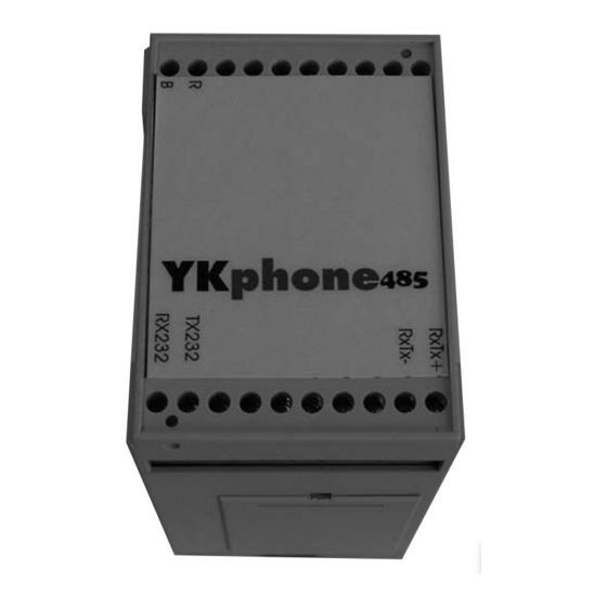
Thermostat Phase control relay The control panel of the unit introduces a sequence and The VCH 20A to 90A units include, as standard equipment, phase failure detector if it detects a phase sequence other the DPC-1 thermostat. To connect the thermostat to the than R-S-T;... - Page 5 International YKtool YKphone 485 This is a device designed for the remote supervision, monitor- The YKtool device is a portable diagnostic and test system for air conditioning units based on the YKtool system. This ing and diagnosis of installations with air conditioning units comprises displaying the main variables of the system as (supermarkets, factories, cinemas, etc.).
- Page 6 Physical data Condensing units VCH 20A VCH 25A VCH 30A VCH 40A VCH 45A VCH 60A VCH 75A VCH 90A Model Amount Nominal power 10.5 2 x 6 2 x 8.1 2 x 10.7 2 x 13.4 Compressor Power supply V.ph.Hz 400.3.50 Degree of protection...
-
Page 7: Installation Instructions
Installation Instructions If, for any reason, this position need be changed sporadically, they will remain in that position a strictly necessary period Inspection of time only. Upon reception, inspect the goods and notify the carrier and the insurance company, in writing, of any possible damage. Warning signs The following signs indicate the existence of potentially dan- Environmental protection... - Page 8 Location of VIR 25 to 90A indoor units Clearances Locate the unit preferably near a wall leading to the exterior so When installing each unit, clearances should be left for: as to make installation, maintenance and draining easier. a) Air intake and discharge of the outdoor unit. b) Connection of the drain pipes and wiring.
- Page 9 Fastening the indoor unit to the ceiling compressor, connecting same electrically as per the dia- grams herein. When fastening, make sure it is completely horizontal, or very slightly tilted towards the drain, so as to avoid possible condensed water leaks (use a bubble level). Drain connections, VIR 25 to 90A indoor unit It is extremely important to be very careful with the support It is necessary to connect a condensed water drain pipe to...
-
Page 10: Pipes To Be Used
Pipes to be used - For interconnecting lines of over 25 metres, oil should be added (30 gr/m. of length). When installing the pipes that join the two units, take special care in checking that the pipes used are kept clean and dry prior to installation. - Page 11 Refrigerant charge and pipe diameters Maximum length Maximum equi- Nominal charge Additional char- Number of Gas line dia- Liquid line dia- in straight valent length Model R-410A ge, grs. circuits meter meter sections of inter- unit interconnec- (Kg.) (per metre) connecting ting pipes pipes (m)
-
Page 12: Electrical Connections
Adjusting the refrigerant charge electronic control board will not be powered and the unit will For lengths over or under 7.5 m., the nominal charge should not operate. In this case, interchange two of the main power be increased or decreased by the grams indicated in the supply intake of the unit. -
Page 13: Limits Of Use
Limits of use Model Voltage limits Min./Max. 342 / 457 WB ° C 15 / 23 15 / 23 15 / 23 14 / 23 14 / 23 14 / 23 14 / 23 14 / 23 min./max. Incoming air temperature to indoor coil Summer DB °... -
Page 14: Electrical Characteristics
Power supply and interconnecting wiring diagram Power supply ������������ ��������� ������������� �� �� �� �� �� �� � � � � ������������� ���������� ������ ������������������ �� �� �� ���������������� ���������� Thermostat ������������������������ �� �� �� � ��� �� �� � �... - Page 15 Electrical characteristics Indoor units Power supply cable Power supply Nominal power Nominal amperage Starting amperage Model section V.ph.Hz (kW) VIR 25A 400.3.50 0.75 4 x 1.5 VIR 40A 400.3.50 4 x 1.5 VIR 45A 400.3.50 4 x 1.5 VIR 60A 400.3.50 4 x 1.5 VIR 75A...
- Page 16 Maintenance of the units sure not to damage them. Since the units are exposed to the outdoor environment, it may be necessary to use water To assure proper operation of the units with minimum electric and an detergent for cleaning. In this case, always apply consumption and a long operating life, a regular maintenance from inside to the exterior, and up and down.
-
Page 17: Technical Characteristics
Technical characteristics General dimensions mm. VCH 20A and 25A ������� ������������� ������� ������������� �� ������� ������������� ������� ������������� ���������� ����������� ���������� ����������� ������������������ � � � � �����������������������... - Page 18 General dimensions mm. VCH 30A and 40A ������� ������������� ������� ������������� �� ������� ������� ������������� ������������ ��������������������� �������������������� ���������� ����������� ���������� ����������� ���������� ����������� ����������������������� ������������������ � ���...
- Page 19 General dimensions mm. VCH 45A and 60A ������� ������������� ������� ������������� �� ������� ������� ������������� ������������� ��������������������� �������������������� ���������� ����������� ���������� ���������� ����������� ����������� ���� � ������������������� ����������������������������������� ��������������...
- Page 20 General dimensions mm. VCH 75A and 90A ������� ������������� ������� ������������� �� ������� ������� ������������� ������������� ��������������������� �������������������� ���������� ����������� ���������� ���������� ����������� ����������� ���� � ������������������� �������������������������...
- Page 21 General dimensions mm. VIR 25A ������� ������� ������������� ������������� ������� ������� ������������� ��� ����������������� ������ ������������ ��������������� ����� ������������������� ���������� ����������� ����������� ���������� ����������� ������� ������������� VIR 40A ������� ������������� ������� ������� ������������� ��� ����������������� ������ ��������������� ������������ ����� ������������������� �����������...
- Page 22 General dimensions mm. VIR 45A and 60A ������� ������������� ������� ������������� ������� ������� ������������� ����� ����������� �������� ������ ���������� �������������� �������������� ������������ ����� ������������������� ���������� ����������� ����������� ���������� ����������� VIR 75A and 90A ������� ������������� ������� ������������� ������� ������� ������������� �����...
- Page 23 Cooling diagram ��������������� ����� ������ ���� ������� ���� ��������� ����� ������� ��������� �� ���������� ������ ����� ����� ����� �� ������� ������� ����� ����� ����������� ����� ������ ��������� ��������� ����� ����� ����� ����� ������������ ������� ����� Variant chart ������������� ������� �������� ��������...
-
Page 24: Nominal Performances
Nominal performances Outdoor unit Indoor unit Summer Winter Cooling Consump- Heating Consump- Model Air flow m³/h Model Air flow m³/h E.E.R. C.O.P. capacity W tion (W) capacity W tion (W) VCH 20A 6 235 VIR 25A 4 590 16 800 5 900 2.85 21 500... - Page 25 Capacity correcting factors in accordance with the length and height between units Heating capacity Cooling capacity ������������ ������������ � � ������ ������ �� �� ��� ���� ���� ��� �� �� �� �� �� �� �� �� � � ����� � �...
-
Page 26: Sensible Cooling Capacities
Sensible cooling capacities Sensible capacity (W) Compressor Dry outdoor Humid intake Total capacity Dry intake air temperature to coil °C (DB) absorbed Model air temperatu- air temperatu- power re °C (DB) re °C (WB) 20 160 5 996 8 828 13 076 15 912 4.08... - Page 27 Sensible cooling capacities Sensible capacity (W) Compressor Dry outdoor Humid intake Total capacity Dry intake air temperature to coil °C (DB) absorbed Model air temperatu- air temperatu- power re °C (DB) re °C (WB) 52 080 15 976 21 638 30 131 35 801 19.5...
- Page 28 Nominal flows bles are valid for the following nominal flows. For other flows, The cooling and heating capacities of the corresponding ta- apply the correcting factors of the corresponding table. Indoor fan nominal Nominal flow Minimum flow Maximum flow available Model pressure VIR 25A...
- Page 29 Indoor fan High Speed Drive H.S.D. and H.S.D.M. configuration for VIR units Fan pulley Motor pulley Motor Automatic switch Adjust- Prim. Shaft Shaft Power Description Code Type Prim. dia. Type Amount ment (1) Code dia. dia. dia. (kW) H.S.D. VIR 25 611991087 SPZ (x 2) H.S.D.M.
- Page 30 Outdoor fan services Available static pressure Air flow Absorbed power Model mm WG 7 055 1.96 1 090 6 420 1.78 6 235 1.73 VCH 20A VCH 25A 7.96 5 715 1.59 12.03 4 990 1.38 3 580 0.99 12 700 3.54 2 900 2.04...
-
Page 31: Electric Diagram
Electric diagram, VCH 20, 25, 30, 40A, 400.3.50 ��������������� ������������� �������� ������ �������������� ��������������� ��� ��� ������ ����� ������������� ������������ ��� ����������������� ����� ����������� ����� ���������������� ��� ������������� ����� ��� ��� ����� ��� ��� ��� ��� ��� ������������ �������������� ��� ���... - Page 32 Electric diagram, VCH 45, 60, 75, 90A, 400.3.50 ��� �������������������� ������������������ ��� �������������������� ������������������ ��� ��� ��� ��� ��� ��� ��� ��� ��� ��� ��� ��� ��� ��� ��� ��� ��� ��� ��� ��� ��� ��� ��� ��� ��� ��� ���...
- Page 33 Electric diagram, VCH 45, 60, 75, 90A, 400.3.50 ��� ��� ��� ������������������� ������������� �������������� ��������������� ��� ������ ����� ������������� ��� ��� ������������ ����� ����� ��� ���������������� ��� ������������� ��� ����� ����� ��� ��� ������������ ��� ���������������� ���������������� ������������� ������������� ������������� ������������...
- Page 34 Configuration of switches...
- Page 35 Cooling capacities (VCH only) lowing table. This coupling is recommended only for use of If the outdoor VCH unit is used with a different indoor unit the cool only model (see cool only operation, page 12). Keep other than the VIR range, this can be selected from the fol- in mind that the indoor unit will need an expansion valve.
-
Page 36: Accessories And Options
Accessories and Options Model Indoor unit accessories Internal electric heater 10 kW Internal electric heater 15 kW Internal electric heater 10 kW Internal electric heater 20 kW Internal electric heater 15 kW Internal electric heater 30 kW Internal electric heater 30 kW Internal electric heater 40 kW... -
Page 37: Technical Specifications
Hot Water Coil - 3-way valve: Bronze body. - Electric actuator: 0-10 V, 24 VAC proportional control. General information - Control board. This hot water coil (optional) is factory-installed; it includes - Temperature probe for water intake, B17. the control board, cables and all material needed for con- - Temperature probe for air impulse, B16. - Page 38 VIR - 45/60 ����� � � � � � � � � VIR - 75/90 ����� � � � � � � � � 3-way valve Actuator Water intake probe, B17 Air impulse probe, B16 Water coil control Automatic air purger Water connecting pipe intake Water connecting pipe outlet...
-
Page 39: Installation
Installation Once the water intake and outlet connections are com- As all components are factory-fitted, at the job site it is nec- pleted, turn the power supply to the machine on. essary to merely connect the 3-way valve intake and output Make sure the green LED (V1) on the coil control board to the how water line. -
Page 40: Operation
Electric actuators, proportional control Attention: Loose cables can cause overheating of terminals VA - 7472 - 9001 (VIR - 25A and 40A) or incorrect operation of the unit. Fire hazards may also exist. Therefore, make sure all cables are connected tightly. Operation Allows generating heat, if conditions are favourable, by modu- �... -
Page 41: Physical Data
Jumper 6. long (stroke length of over 1/2 inch) stroke selection No function. By factory default, with jumper. jumper. By default, factory-set to long position (L). Jumper 3. Configures the direct/inverse action jumper so that the Actuator selection jumpers valve shaft goes in the desired direction. By default, fac- VA - 7472 - 9001 (VIR - 25A and 40A) tory-set to lower position, inverse action (A1). - Page 42 Data with water, without GLYCOL Water temperature (intake - outlet) Water 90 - 70 80 - 60 70 - 50 Air flow Unit volume in D air temp. D air temp. D air temp. Heat. cap. O flow Heat. cap. O flow Heat.
- Page 43 Wiring diagram VIR 45/90 ������ ����������������� �� ��� �� ��� ��������������������� �������������������� ��� ������������� ���� ���������� ����� ��� �� ���� �� ������������������������ ��� ��� ��� ���������� �� ����������� ��� ��� ����� ����� ��� ����� ���� ��������� ������� ��� ������ ���� ����...
- Page 44 Internal Electric Heaters for VIR 25A to - Power supply contactor with a 24 V coil. - Two thermal protectors located at the top of the heater. The first, with automatic reset, disconnects the heater when a The internal electric heaters are designed to provide backup temperature of 77°...
- Page 45 General dimensions mm. VIR 25A ��� �� ��� ���� VIR 40A ��� ��� ��� �� ��� ���� VIR 90A ��� ��� ��� �� ��� ���� For installing in VIR 45A and 60A 1 160 VIR 75A and 90A 1 380...
- Page 46 Assembly and general dimensions mm Electric box of the VCH unit ��������������� �������������� ������������������������������������ �� �� �� �� �� �� �� �� �� ��� �� �� �� �� �� �� �� �� � �� ��� ��� ��� ��� ��� �� ��...
-
Page 47: General Characteristics
General characteristics Automatic Power supply Front sur- Pressure Power supply Power Consumption Stages switch (1) cable section (2) face drop (3) Heater model V.ph.Hz VIR 25A 400.3.50 0.53 VIR 25A 400.3.50 0.53 VIR 40A 400.3.50 0.74 VIR 40A 400.3.50 0.74 VIR 45 and 60A 400.3.50 0.98... -
Page 48: Wiring Diagram
Wiring diagram Heater 10, 15kW, 400.3.50 / VIR 25A, 40A, 45A and 60A ����� ��������� ��������� ���������� ������ ������ ������ ������� �� �� ��� �� � �� �� �� ��� �� �� �� � ������������������ �� �� �� ������������ � ������... - Page 49 Wiring diagram Heater 20, 30, 40kW, 400.3.50 / VIR 40A, 45A, 60A, 75A and 90A ������������ ���������� ������������ ����� ������ ������� ������ ������ �� �� � ���� ����������������� �� �� �� �� � �� �� �� �� �� �� �� ��...
- Page 50 Vertical air discharge for VIR 25A to 90A 3.- Once the fan is fastened to the top panel 5 , install same on the unit. The VIR 25A to VIR 90A units require a conversion that 4.- Fit angles 7 to the unit and fasten the fan to these an- includes: gles.
- Page 51 Vertical air discharge conversion for VCH 20A, leys are aligned (the centre of the tensor will be at about 20 mm. from the face of the fan) (Fig. 3). 25A 30A and 40A 4.- Fasten the fan to the tabs "C" and supports "D" of the This Kit allows converting the standard horizontal air dis- upper panel 3 , before or after mounting same on the charge, in outdoor units VCH 20A to 40A, to a vertical dis-...
- Page 52 General dimensions mm. Fig.4 � � � � � � � � � � � � � Model VCH 20A and 25A 1 364 1 063 VCH 30A and 40A 1 741 1 440...
- Page 53 Vertical air discharge conversion for VCH 45A, leys are aligned (the centre of the tensor will be at about 20 mm. from the face of the fan) (Fig. 3). 60A 75A and 90A 4.- Fasten the fan to the tabs "C" and supports "D" of the This Kit allows converting the standard horizontal air dis- upper panel 3 , before or after mounting same on the charge, in outdoor units VCH 45A to 90A, to a vertical dis-...
- Page 54 General dimensions mm. Fig.4 � � � � � � � � � � � � � Model VCH 45A and 60A 2 240 1 990 VCH 75A and 90A 2 660 2 410...
-
Page 55: Programming And Adjustment
Condensation Control VCH 20 to 90A key: - In standby mode, displays pressure switch 2 value. This option controls the head pressure in the summer cycle - In programming mode, it is used to move on to the previ- by varying air flow in the outdoor coils. This air flow variation ous parameter and to decrease the values of same. - Page 56 diagram. 9.- Press to confirm the change. ��� 16.- Drill a 22 mm. Ø hole on the left side front panel (next 10.- Press to save the changes and exit the program- �������� to damper motor) and insert the guide. Insert the motor ming mode.
-
Page 57: Location Of Components
2.- Turn the unit off and program the thermostat in the sum- 17.- Connect all cables supplied, in accordance with the mer cycle. corresponding wiring diagram. 3.- Start the compressors and check to be sure that when 18.- Turn main power supply on and program the control the pressure begins to rise above the programmed unit. - Page 58 Vertical air discharge VCH 20 - 90A ������������� ������� ������� �������� ������� ��������� �������� ������������� �������� ������� ��������� �������� ������������� �������� ������������� ������� ��������� ������� �������� � ����������� � ����������������� ����������������� ���������������� ���������������� ������������� ������������� Machine VCH-20 to 25A VCH-30 to 40A VCH-45 to 60A VCH-75 to 90A...
- Page 59 VCH-20A to 40A �� �� ��� �� �� �� �� �� �� �� �� �� �� �� �� ����������� ��� �� ������������� ��� ��� �� �� �� �� ��� �� �� � �� �� �� �� �� �� �� �� �� �� ���...
- Page 60 VCH-20A to 40A � � �� � �� �� �� �� �� �� �� �� �� � � �� � � � �� �� � � � � �� ��� ��� �� � � � �� � � � � �...
-
Page 61: Wiring Diagrams
Wiring diagrams � �� ��� ��� �� �� �� ��� ��� �� �� ����� ����� ����� � ��� �� �� ��� ������������������������ � � ��������������������������� ������������������� ����� ������������������������������ � � � � � � � �� �������������� ����� �������� ������� �������... - Page 62 Wiring diagrams �� �� �� ��� ��� ��� �� �� �� �� �� ��� ��� �� ��� ��� ��� �� �� �� �� �� ����� ����� ����� ����� � � ��� �� �� ��� �������������������������������� � � �������������������������� ������������������ ����� �����������������������������...
-
Page 63: Tray Heater
Tray Heater This flexible cable heater can be used in cold climates to ���������� avoid the forming of ice and the subsequent obstruction at ������������� �������������� the tray drain of the heat pumps. This accessory includes: ������������ ������������� ���� ���� Models VCH 20 to 40A - 1 Flexible cable heater with a thermostat. - Page 64 Economiser from the mouth of the duct connected to the machine. These instructions provide the necessary information for cor- 6. Assembly of enthalpy probe, Ref. C7400A (option not ap- rect installation, at the job site, of the economiser dampers. plicable). The enthalpy probes are an optional accessory The economiser is located in the return section of the VIR that cannot be installed with the VIR unit economiser.
- Page 65 Caution: calls for cool or heat, the damper goes back to minimum renovation. If there is no call from the thermostat and Loose cables can cause overheating of terminals the indoor fan is in auto mode, the fan turns off and the or incorrect operation of the unit.
- Page 66 Economiser General dimensions mm. Economiser Weight VIR 25A 1 109 VIR 40A 1 352 VIR 45A / 60A 1 935 1 499 VIR 75A / 90A 2 205 1 724...
- Page 67 Economiser assembly, standard configuration � ����������� ��������������� � ���������� � � The outdoor air damper is at the top. Confront the economiser with the frame of the corresponding VIR unit. To fasten use the screws, nuts and washers 1 supplied. To install said screws 1 , first remove the side panels 2 .
- Page 68 Return, outdoor and impulse air sensor ������� ������ ���������� ������ ������� ��������������� ���������� �������������������� Economiser control board ����� ��� ��� ��� � � �� � ��� ��� ��� �� ����� ��� �� �� ����� ��� �� �� �� Status Indication Board is not connected Board is not in service Flashing...
- Page 69 Wiring diagram ������ ��� ��� �� ��� ��� ���� ����� ��� �� ���� �� ����������� ��� ��� ��� ������������ �� ��� ��� ��� ���������� ����������� ������� ������� ������ ����� ����� ����� ����� ��� ���� �� �� ��� ���� ��� ��� ����...
-
Page 70: Status Indicating Leds
Static starter (Soft Start) magnetic relays that plot the semiconductors during active The RSHR4012BV20 starter is a compact control unit with operation when the ramps are activated. The starting time, a motor with AC semiconductors, designed for soft starting the stopping time and the initial torque are adjusted by means and stopping of three-phase motors for centrifugal fans, with of independent potentiometers. - Page 72 www.johnsoncontrols.com...
Need help?
Do you have a question about the York Vitality Series and is the answer not in the manual?
Questions and answers