Table of Contents
Advertisement
Quick Links
Installation
and
Maintenance
Manual
INVERTER-DRIVEN
MULTI-SPLIT SYSTEM
HEAT PUMP
AIR CONDITIONERS
Type
(H,Y,C)ICS015B21S
(H,Y,C)ICS024B21S
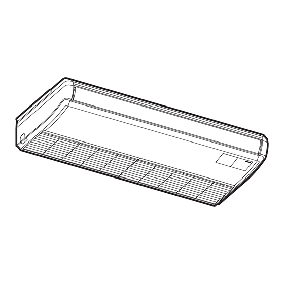
Ceiling Suspended
(H,Y,C)ICS030B21S
(H,Y,C)ICS036B21S
IMPORTANT:
READ AND UNDERSTAND
THIS MANUAL BEFORE
INSTALLING THIS HEAT
PUMP AIR CONDITIONER.
KEEP THIS MANUAL FOR
FUTURE REFERENCE.
Model
P5417058
Advertisement
Table of Contents

Related Manuals for Johnson Controls HICS024B21S


Summary of Contents for Johnson Controls HICS024B21S
- Page 1 Installation Maintenance Manual INVERTER-DRIVEN MULTI-SPLIT SYSTEM HEAT PUMP AIR CONDITIONERS Type Model (H,Y,C)ICS015B21S (H,Y,C)ICS024B21S Ceiling Suspended (H,Y,C)ICS030B21S (H,Y,C)ICS036B21S IMPORTANT: READ AND UNDERSTAND THIS MANUAL BEFORE INSTALLING THIS HEAT PUMP AIR CONDITIONER. KEEP THIS MANUAL FOR FUTURE REFERENCE. P5417058...
- Page 2 ATTENTION Each model number and all matching model numbers within a system must have the same version of software. Follow these steps to verify that your product model numbers have the same version of software. • Access the main printed circuit board in each product. •...
- Page 3 Important Notice ● Johnson Controls, Inc. pursues a policy of continuing improvement in design and performance in its products. As such, Johnson Controls reserves the right to make changes at any time without prior notice. ● Johnson Controls cannot anticipate every possible circumstance that might involve a potential hazard.
-
Page 4: Table Of Contents
TABLE OF CONTENTS 1. Introduction ................................1 2. Safety Instructions ..............................1 3. Before Installation ..............................8 3.1 Combinations of Outdoor Unit and Indoor Unit .................... 8 3.2 Transportation and Handling ........................8 3.3 Factory-Supplied Accessories ........................9 4. Installation Work ..............................12 4.1 Position of Suspension Bolts ........................ -
Page 5: Introduction
● This system should be installed by personnel certified by Johnson Controls, Inc. Personnel must be qualified according to local, state and national building and safety codes and regulations. Incorrect installation could cause leaks, electric shock, fire or explosion. In areas where Seismic ‘’Performance... - Page 6 This unit is a pressurized system. Never loosen threaded joints while the system is under pressure and never open pressurized system parts. ● Johnson Controls will not assume any liability for injuries or damage caused by not following steps outlined or described in this manual. Unauthorized modifications to Johnson Controls' products are prohibited as they…...
- Page 7 Installation Precautions To reduce the risk of serious injury or death, the following installation precautions must be followed. ● When installing the unit into… ▫ A wall: Make sure the wall is strong enough to hold the unit’s weight. It may be necessary to construct a strong wood or metal frame to provide added support.
- Page 8 Controls. uses only refrigerants that have been approved for use in the unit’s intended home country or market. Johnson Controls' distributors similarly are only authorized to provide refrigerants that have been approved for use in the countries or markets they serve. The refrigerant used in this unit is identified on the unit’s faceplate and/or in the associated manuals.
- Page 9 When shielded cable is applied, proper bonding and termination of the cable shield is required as per Johnson Controls guidelines. Plenum and riser ratings for communication cables must be considered per application and local code requirements.
- Page 10 ● Turn OFF and disconnect the unit from the power supply when handling the service connector. Do not open the service cover or access panel to the indoor or outdoor units without turning OFF the main power supply. ● After stopping operation, be sure to wait at least five minutes before turning off the main power switch.
- Page 11 ● Proper handling of this unit requires two people. Safe handling and installation of the indoor unit requires the strength of two people. Mounting the unit alone may cause injury due to a fall of the unit. Although the unit may be girded with steel banding, do not use it for transportation. Avoid contact with finned surfaces of the heat exchanger as sharp edges can cause severe injury to hands and fingers.
-
Page 12: Before Installation
Before Installation Combinations of Outdoor Unit and Indoor Unit The combination capacity of the indoor unit against the outdoor unit is selected depending on the outdoor unit capacity. Refer to the “Installation and Maintenance Manual” for the outdoor unit to decide the required combination of indoor and outdoor units, and the combination unit capacity. -
Page 13: Factory-Supplied Accessories
Factory-Supplied Accessories 1. Check to ensure that the following accessories are packed with the indoor unit. The screws, washers, and flare nuts are packed in the pipe insulation. Accessory Qty. Purpose Suspension Bracket For Installing Indoor Unit Washer For Suspension Bracket Pipe Insulation (Large) For Refrigerant Piping Connection... - Page 14 2. Do not insert or leave any foreign objects inside the indoor unit and verify that no foreign objects remain inside the indoor unit before installation and the test run. Failure to do this can result in equipment failure and damage to the unit. 3.
- Page 15 • For the indoor unit with a motion sensor, the detecting area for the motion sensor is shown in the figure below. Detecting Area Depth 23 ft (7m) Floor-to-Ceiling Height 8.9 ft (2.7m) Detecting Area Detecting Area 2.6 ft (0.8m) from Floor Level 5.9 ft (1.8m) 23.6 ft (7.2m)
-
Page 16: Installation Work
Installation Work Position of Suspension Bolts 1. Determine the final location and installation direction of an indoor unit with care to spacing for piping and wiring. 2. After the position of the indoor unit is determined, make holes in the ceiling to install the suspension bolts. -
Page 17: Mounting Indoor Unit
Mounting Indoor Unit 1. Pattern Board for Installation The pattern board for the installation is printed on the packing. When making holes in the wall and ceiling, use the pattern board that has printed hole positions for suspension, refrigerant pipe and condensate pipe. Upper Cap The pattern board is attached in the upper cap. -
Page 18: Installation Of Wired Controller
B. Hanging Indoor Unit without Suspension Bracket (If there is not enough service space between the ceiling and the indoor unit, hang the indoor unit using procedures of A above.) a. Determine the position to install the Suspension Bolt (Field-Supplied) suspension bolt. -
Page 19: Refrigerant Piping Work
Refrigerant Piping Work Use the specified non-flammable refrigerant (HFC R410A) for the outdoor unit refrigerant system. Do not charge the unit with anything other than HFC R410A, such as hydrocarbon refrigerants (propane and isobutene), oxygen, and other flammable gases (acetylene, ammonia, and so forth), or any poisonous gases when installing, maintaining or moving the unit. - Page 20 2. Use the specific flare nut attached with the unit. 3. Verify that there are no scratches or burrs stuck to internal surfaces, or surface distortion at the flared opening. 4. Before tightening the flare nut, apply a small amount of oil (field-supplied) to the flare face. (Do not apply any oil to the backside of the flare or the threads.) Tighten the liquid pipe flare nut to the specified torque while using a backup wrench to prevent damage to the unit.
-
Page 21: Piping Connection Work
Piping Connection Work 5.3.1 Position of Piping Connection The piping connection is performed inside the indoor unit. The pipe connection can be performed from three directions - rear, right and upper. For rear and upper pipe connection, the plastic cap is attached at the knockout hole for the refrigerant pipe and the condensate pipe. -
Page 22: Access Of Piping Connection
● Piping from Rear Side inch (mm) Upper Surface Cap (Rear Side) 3 (76) 4-3/4 (121) 2-7/16 (62) Condensate Pipe Connection (VP20, Left Side) View from Front ● Piping from Right Side ● Piping from Upper Side Cap (Upper Side) Hole for Condensate Pipe Conncetion (Knockout hole) -
Page 23: Condensate Piping
Condensate Piping Do not run condensate piping into underground areas near sanitary or sewage lines where toxic and corrosive gases can seep into the system. This creates a pathway for the flow of poisonous gas to penetrate inhabited areas. NOTICE ●... - Page 24 Connecting Condensate Hose a. Insert the hose into the hose clamp. b. Push the condensate hose onto the drain adaptor until the hose reaches the end of the condensate pan. (If the condensate hose is not inserted completely, it causes water leakage.) c.
- Page 25 After the condensate piping work is completed, check that water flows smoothly by pouring water into the condensate pan using a hose. NOTE: The optional drain-up mechanism is required when the condensate piping is connected from the upper surface of the indoor unit. For details, refer to the installation and maintenance manual for the drain-up mechanism.
-
Page 26: Electrical Wiring
Electrical Wiring ● All electrical work must be done as outlined in this manual and in accordance with this manual. Substandard work can result in fire and damage to the unit. ● Use specified cables between units and choose the cables correctly. If not, an electrical shock or fire may occur. -
Page 27: Details Of Electrical Wiring Connection
7.2.2 Details of Electrical Wiring Connection Details for electrical wiring capacity of the outdoor unit should be referenced according to the installation and maintenance manual for the outdoor unit. Adjusting the DIP switches may be required depending on the arrangement with the outdoor unit. Select wiring capacity according to Table 7.1. -
Page 28: Position Of Electrical Wiring Connection
Position of Electrical Wiring Connection ● The electrical wiring connection for the indoor unit is shown in Section 7.2.2. For details relating to the intermediate connections between the indoor unit and the decorative panel, refer to installation of the decorative panel. ●... - Page 29 All electrical work should be performed in strict accordance with electrical schematics in the "Installation and Maintenance Manual". If Power Supply Voltage (208V/230V) is introduced into the Communication Line: If 208V/230V are applied to the communication line at (Terminals 1 and 2 of TB2) by mistake, the fuse on the PCB for the communication line will blow.
-
Page 30: Caution For Electrical Wiring
NOTICE 1. The DIP switch settings for the outdoor unit should be performed in accordance with the "Installation and Maintenance Manual" for the outdoor unit. 2. Be aware that communication cable for the wired controller is required in these instances: a. -
Page 31: Wiring Connections
Wiring Connections Wiring connections for the indoor unit are shown below. 1. The wiring connection for the indoor unit is shown in the figure below. Upper Side Communication Cable and Wired Controller Cable 1/2 inch (13mm) Opening Power Supply Wiring Rear Side 7/8 inch (22.2mm) Conduit Opening 2. -
Page 32: Dip Switch Settings
DIP Switch Settings 1. Turn OFF the power supply to both indoor and outdoor units before adjusting DIP switch settings. Otherwise, the settings are invalidated and do not take effect. 2. Positions of DIP switches on the PCB are shown below. DSW5 (Refrigerant System No. - Page 33 Refrigerant System No. Setting (RSW2 and Refrigerant System No. Setting DSW5 (Tens Digit) RSW2 (Units Digit) DSW5) Ex.) Set at No.5 Cycle DSW5 This setting is required. The unit arrives with all Setting Set by inserting Position slotted screwdriver settings in the OFF position. into the groove.
-
Page 34: Function Selection By Wired Controller
Function Selection by Wired Controller Each function can be selected with the wired controller. Refer to the “Installation and Maintenance Manual” for the wired controller and the “Engineering Manual” for details. (1) Press and hold "Menu" and "Back/Help" simultaneously for at least 3 Test Run Menu seconds during the normal mode (when unit is not operated). -
Page 35: Setback Operation
Function Setting Condition (Underlined Part is Factory Setting) Optional Function Selection Unit Item Automatic COOL/HEAT Operation Available Available Dual Setpoint Available Available Cooling/Heating Changeover Temperature (1.0) (1.5) (2.0) (2.5) (3.0) (0.5) Setback Temperature Compensation (During card key removal, setpoint is setbacked) (2.5) (3.0) (3.5) -
Page 36: Test Run
Test Run Before Test Run Verify that there are no problems with the installation, and do not perform the test run until all the following procedures have been accomplished. Refer to the "Installation and Maintenance Manual" for the outdoor unit for details on test run operations from the outdoor unit. - Page 37 ● The total number of connected indoor units is indicated on the Liquid Crystal Display (LCD). In the case of a twin combination (set of two indoor units), the total number of the connected indoor units is displayed as “2 units”, and where there is a triple combination (set of three indoor units), the total number of the connected indoor units is displayed as “3 units”.
- Page 38 Checking the Motion Sensor 1. Perform the motion detection (waving a hand) under the motion sensor of the selected indoor unit for approximately 10 to 15 seconds. 2. Check the value of “q3” to "q6" after 30 seconds* from starting the motion detection at Item 1. The detection information from the motion sensor against the motion detection is displayed in a range of 0% to 100%.
- Page 39 ● The RUN indicator on the wired controller for the indoor unit flashes orange (0.5 second ON/ 0.5 second OFF), indicative of a fault or error having been generated with activation of protection devices during the test run phase. Alarm code, unit model code, and the number of interconnected indoor units is displayed on the LCD as shown below.
-
Page 40: Alarm Codes
Alarm Codes Alarm (Troubleshooting) Code Table Code Category Nature of Problem Likely Cause Activation of a protection device Activation of the float switch. (High water level present in Indoor Unit (float switch). the condensate pan.) A problem exists in the piping. Activation of protection device. - Page 42 © 2017 Johnson Controls, Inc. P5417058-rev.1 Code No. LIT-12012967 Revised January 2018...
Need help?
Do you have a question about the HICS024B21S and is the answer not in the manual?
Questions and answers