Table of Contents
Advertisement
Advertisement
Table of Contents

Related Manuals for Sierra Wireless AirLink RV55


Summary of Contents for Sierra Wireless AirLink RV55
- Page 1 AirLink RV55 Hardware User Guide 41113042 Rev. 1...
- Page 2 Sierra Wireless accepts no responsibility for damages of any kind resulting from delays or errors in data transmitted or received using the Sierra Wireless product, or for failure of the Sierra Wireless product to transmit or receive such data.
- Page 3 Sierra Wireless product. Patents This product may contain technology developed by or for Sierra Wireless Inc. This product ® includes technology licensed from QUALCOMM .
-
Page 4: Contact Information
AirLink RV55 Hardware User Guide ® ® Windows and Windows Vista are registered trademarks of Microsoft Corporation. ® ® Macintosh and Mac OS X are registered trademarks of Apple Inc., registered in the U.S. and other countries. ® QUALCOMM is a registered trademark of QUALCOMM Incorporated. Used under license. -
Page 5: Table Of Contents
Introduction to the AirLink RV55 ........ - Page 6 AirLink RV55 Hardware User Guide Step 6—Check the Router Operation ........35 LED Behavior .
- Page 7 Contents Accessories ............62 DC Power Cable (Black Connector) .
-
Page 8: Introduction To The Airlink Rv55
1: Introduction to the AirLink RV55 ® ® The Sierra Wireless AirLink RV55 LTE-A Pro router is a compact, intelligent and fully- featured communications platform that provides real-time wireless capabilities for fixed and mobile applications. It is intended for use in industrial settings such as: •... - Page 9 Introduction to the AirLink RV55 • Industry leading warranty includes support, software updates, and advance replacement • Power Saving Features, including: · Processor Power Saving Mode · LED power saving mode · Standby mode · Power saving strategies such as turning off unused interfaces (USB, Serial, Ethernet), turning off GNSS, and adjusting the Ethernet data rate •...
-
Page 10: Description
AirLink RV55 Hardware User Guide Description Back Panel Cellular Antenna Connector 9-pin RS-232 Serial Port Diversity (See Connect the Antennas page 19.) Antenna Connector (See Serial Port on page 22.) (See Connect the Antennas page 19.) Power Connector RJ-45 Ethernet Port USB 2.0 Micro-AB Port... -
Page 11: Router Configuration And Management
For a complete list of AT Commands, refer to the ALEOS Software Configuration User Guide. Power Modes The AirLink RV55 router has three power modes: • On—The CPU and the radio are on. The current draw is 900 mW (75 mA @ 12 VDC) when the router is idle (i.e. -
Page 12: Power Saving Features
AirLink RV55 Hardware User Guide Power Saving Features Table 1-1 provides a quick reference to the RV55 power saving features. For more information, refer to the ALEOS Software Configuration User Guide. Table 1-1: Power Saving Features Feature Where to configure... -
Page 13: Sample Power Consumption Scenarios
Introduction to the AirLink RV55 Sample Power Consumption Scenarios Note: All power consumption figures are preliminary. Table 1-2: Power Consumption Scenarios Scenario Radio Ethernet Serial GNSS Processor Power Power Power Saving Saving Mode Mode Standby Mode — — — —... -
Page 14: Dual Sim
AirLink RV55 Hardware User Guide Dual SIM The AirLink RV55 router has two SIM card slots. You can decide which slot is the Primary SIM card. When the router is powered on or reboots, it automatically connects to the network associated with the Primary SIM card. If no card is present in that slot, it connects to the network associated with the Secondary SIM card. -
Page 15: Installation And Startup
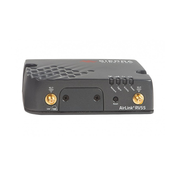
2: Installation and Startup This chapter shows how to connect, install and start the Sierra Wireless RV55 router. It also describes the front panel LEDs, and I/O functionality. Note: Field wiring and connections in hazardous locations must be connected as per the wiring methods requirement for Class 2 circuits mentioned in the National Electric Code and the Canadian Electric Code. -
Page 16: Step 1-Insert The Sim Cards
AirLink RV55 Hardware User Guide Step 1—Insert the SIM Cards The AirLink RV55 router has two mini-SIM (2FF) card slots. The upper slot is Slot 1 and the lower slot is Slot 2. ACEmanager references these slot numbers, and by default, the SIM card in Slot 1 is the Primary SIM card. -
Page 17: Step 2-Mounting The Rv55 Router
Mounting Brackets The RV55 router comes with mounting screws. An optional DIN rail mounting bracket (P/N 6000659) is available from Sierra Wireless. Flat Surface Mount If you are mounting the RV55 router on a flat surface, use the mounting screws that come with the router. -
Page 18: Din Rail Mount
Power Consumption Scenarios on page 13. Note: The DIN rail mounting bracket and clip in the Sierra Wireless kit should only be used on horizontally-mounted DIN rail. Rev. 1 June 2019 41113042... -
Page 19: Grounding The Rv55 Router Chassis
Installation and Startup Grounding the RV55 Router Chassis For DC installations (with a fixed “system” ground reference), Sierra Wireless strongly recommends always grounding the RV55 chassis to this system ground reference. To ensure a good grounding reference, either: • Attach the RV55 to a grounded metallic surface. - Page 20 AirLink RV55 Hardware User Guide To install the antennas: 1. Connect the cellular antenna to the SMA cellular antenna connector. Mount the cellular antenna so there is at least 20 cm between the antenna and the user or bystander. 2. Connect a second antenna to the SMA Diversity antenna connector.
-
Page 21: Recommended Antenna Separation
The recommended antenna separation is related to the band frequency/wavelength. To accommodate the shortest frequency/longest wavelength band supported by the RV55, Sierra Wireless recommends a minimum antenna separation of 214 mm for best results, and if necessary, a separation of 107 mm for acceptable results. -
Page 22: Usb Port
The same serial port can be configured as a dual 4-wire serial port, and connect to devices with a Y cable (Sierra Wireless part number 6001238). The Dual Port Mode setting is available in ACEmanager under Serial > RS232 Configuration > General. - Page 23 Installation and Startup Figure 2-5: DB-9 Female Serial Connector Table 2-2: Serial Connector Pin-out (Single Port Mode) Name Description Type Data Carrier Detect Transmit Data Receive Data Data Terminal Ready Main GND. Connected internally to BOARD GND Data Set Ready Ready To Send Clear To Send Not connected...
-
Page 24: Step 5-Connect The Power
AirLink RV55 Hardware User Guide Step 5—Connect the Power The AirLink RV55 router comes with a 3 meter (10 ft.) DC power cable. You can also purchase an optional AC adapter. Note: Electrical installations are potentially dangerous and should be performed by personnel thoroughly trained in safe electrical wiring procedures. -
Page 25: Power Connector On The Rv55 Router
Installation and Startup Power Connector on the RV55 Router White Pin 3 Ignition Sense Ignition switch or external Green solar power low voltage Pin 4 disconnect device GPI/O Pin 1 Optional: Connect Power to switch, relay or external device Black Pin 2 4.0 A fast-acting Ground... - Page 26 Wire Color Ignition White Sierra Wireless recommends using the Ignition Sense wire to turn the router Sense off. It should not be turned off by disconnecting the power. Note: If you do not connect pin 3 to the ignition, you MUST connect it to the positive terminal of your power supply or battery.
-
Page 27: Wiring Diagrams
Pin 1 (Power) —Use the red wire in the DC cable to connect Pin 1 to the power source. Include a 4.0 A fast-acting fuse in the input power line. Sierra Wireless recom- mends using a continuous (unswitched) DC power source. -
Page 28: Fixed Installation
Pin 1 (Power) —Use the red wire in the DC cable to connect Pin 1 to the power source. Include a 4.0 A fast-acting fuse in the input power line. Sierra Wireless recom- mends using a continuous (unswitched) DC power source. -
Page 29: I/O Configuration
Pin 1 (Power) —Use the red wire in the DC cable to connect Pin 1 to the power source. Include a 4.0 A fast-acting fuse in the input power line. Sierra Wireless recom- mends using a continuous (unswitched) DC power source. -
Page 30: Rev. 1 June 2019
AirLink RV55 Hardware User Guide Note: During bootup, the I/O settings remain in their default state: the internal pull-up resistor is disabled, and output current sink switch is open. After bootup, any custom I/O settings are applied. This may take approximately 30 seconds after the router is restarted or powered on. -
Page 31: Digital Input
Installation and Startup Digital Input You can use the green wire to connect Pin 4 to a digital input to detect the state of a switch such as a vehicle ignition, or to monitor an external device such as a motion detector, a remote solar panel, or a remote camera. - Page 32 AirLink RV55 Hardware User Guide High Side Pull-up / Dry Contact Switch Input You can use the green wire to connect Pin 4 to a dry contact switch. The dry contact switch is not available in Standby mode. RV55 Internal pull-up...
-
Page 33: Analog Input
Installation and Startup Analog Input You can use the green wire to connect Pin 4 to an analog sensor. As an analog input (voltage sensing pin), the router monitors voltage changes in small increments. This allows you to monitor equipment that reports status as an analog voltage. Pin 4 detects inputs of 0.5–36 V referenced to ground. - Page 34 AirLink RV55 Hardware User Guide Low Side Current Sink Output You can use Pin 4 as a low side current sink, for example, to drive a relay. RV55 Internal pull-up resistor Protection External solenoid/relay circuit Circuitry = 500 mA (Typ)*...
-
Page 35: Step 6-Check The Router Operation
— Step 6—Check the Router Operation 1. When power is supplied to the AirLink RV55 router, it powers up automatically, as indicated by the flashing LEDs. If it does not turn on, ensure that the: · Power connector is plugged in and supplying voltage between 7–36 V. -
Page 36: Led Behavior
Solid Amber Fair signal (equivalent to 2–3 bars) Flashing Amber Poor signal (equivalent to 1 bar) If possible, Sierra Wireless recommends moving the router to a location with a better signal. Flashing Red Inadequate (equivalent to 0 bars) Sierra Wireless recommends moving the router to a location with a better signal. -
Page 37: Ethernet Leds
Installation and Startup Table 2-11: LED Behavior Color / Pattern Description LED Power Saving Mode Network Solid Green Connected to an LTE network Solid Amber Connected to a 3G or 2G network Flashing Green Connecting to the network Flashing Green (3 Network Ready—WAN over Wi-Fi (router is in Wi-Fi client mode) sec. -
Page 38: Step 7-Startup And Software Configuration
AirLink devices • Single click over-the-air firmware updates to all your routers and gateways • Compatible with all carriers or mobile network operators To get started, contact your Sierra Wireless Partner or visit www.sierrawireless.com/ ALMS Rev. 1 June 2019 41113042... -
Page 39: Configuring With Amm
If you require a network management solution deployed in your data center, contact your Sierra Wireless sales representative for a demonstration of AMM capabilities. Configuring with AT Commands For a complete list of AT commands, refer to the ALEOS Software Configuration User Guide. -
Page 40: Recovery Mode
AirLink RV55 Hardware User Guide Recovery Mode If the router fails to boot properly, it automatically enters recovery mode, or, if the router is unresponsive to ACEmanager input and AT commands, you can manually put the router into recovery mode. -
Page 41: Specifications At A Glance
3: Specifications at a Glance This chapter provides the specifications for the RV55 router. Certification and Interoperability Emissions / Immunity • Industry Canada • Safety CB Scheme • UL 60950 • Industry Certification E-Mark (UN ECE Regulation 10.04), ISO7637-2 • for Vehicles SAE J1455 (Shock &... -
Page 42: Reliability Specifications
AirLink RV55 Hardware User Guide Test Method Category Description MIL-STD-810G, Humidity 10 × 48-hour cycles: Test method 507.5 4-hour ramp to 60 °C (95% humidity), hold 8 hours • 4-hour ramp down to 30 °C (85% to 95% relative •... -
Page 43: Mobile Network Operator Certification
Specifications at a Glance Mobile Network Operator Certification • Verizon Wireless • AT&T/FirstNet • Rogers • Bell Mobility • Telus • Telstra a. Certification planned Rev. 1 June 2019 41113042... -
Page 44: Host Interfaces
By default, the USB port is configured as a virtual Ethernet port. A Windows driver must be installed on the PC in order to support USB • use. The drivers are available for download on Sierra Wireless’ support web site: source.sierrawireless.com/resources/airlink/software_downloads/... -
Page 45: Sim Card Interface
Specifications at a Glance Ethernet 10/100/1000 Base-T RJ-45 Ethernet • IEEE 802.3 Ethernet specification for 1000 Mbps speed (Gigabit • Ethernet) with fallback to 100 or 10 Mbps (Cat 5e or Cat 6 cable is required for Gigabit Ethernet) Auto-crossover support •... -
Page 46: Operating Voltage
The device looks for a qualified voltage on this pin as part of the power up sequence. If it doesn’t see it, the device will not turn on. If you are using a Sierra Wireless AC power adapter, the connection is inside the cable. -
Page 47: Protocols
Specifications at a Glance Protocols • Network: TCP/IP, UDP/IP, DNS • Routing: NAT, Host Port Routing, DHCP, PPPoE, VLAN, VRRP, Reliable Static Route • Applications: SMS, Telnet/SSH, Reverse Telnet, SMTP, SNMP, SNTP • Serial: TCP/UDP PAD mode, Modbus (ASCII, RTU, Variable), PPP •... -
Page 48: Radio Frequency Bands
AirLink RV55 Hardware User Guide Radio Frequency Bands Use the following table as a guide to the radio frequencies supported by the RV55 radio modules. To determine which radio module your router has, refer to the label on the bottom of the router, or in ACEmanager, go to Status >... - Page 49 Specifications at a Glance Table 3-3: RV55 LTE-A Pro Radio Module EM7511 North America Radio Band Frequency (Tx) Frequency (Rx) Technology Generic Verizon AT&T Wireless Band 1 1920–1980 MHz 2110–2170 MHz Band 2 1850–1910 MHz 1930–1990 MHz ...
- Page 50 AirLink RV55 Hardware User Guide Table 3-3: RV55 LTE-A Pro Radio Module EM7511 North America (Continued) Radio Band Frequency (Tx) Frequency (Rx) Technology Generic Verizon AT&T Wireless HSPA Band 1 1920 –1980 MHz 2110–2170 MHz ...
- Page 51 Specifications at a Glance Table 3-4: Radio Module EM7511 Conducted Transmit Power Band Conducted Tx Notes Power (dBm) Band 1 Band 13 +23±1 Band 2 Band 14 Band 3 Band 18 Band 4 Band 19 Band 5 Band 20 Band 8 Band 26 Band 9 Band 30...
- Page 52 AirLink RV55 Hardware User Guide Table 3-5: RV55 LTE-A Pro Radio Module EM7565 Global Radio Band Frequency (Tx) Frequency (Rx) Technology Generic Telstra Band 1 1920–1980 MHz 2110–2170 MHz Band 2 1850–1910 MHz 1930–1990 MHz Band 3 1710–1785 MHz...
- Page 53 Specifications at a Glance Table 3-5: RV55 LTE-A Pro Radio Module EM7565 Global (Continued) Radio Band Frequency (Tx) Frequency (Rx) Technology Generic Telstra HSPA Band 1 1920 –1980 MHz 2110–2170 MHz Band 2 1850–1910 MHz 1930–1990 MHz Band 4 1710–1755 MHz 2110–2155 MHz...
- Page 54 AirLink RV55 Hardware User Guide Table 3-6: Radio Module EM7565 Conducted Transmit Power Band Conducted Tx Notes Power (dBm) Band 1 Band 13 +23±1 Band 2 Band 18 Band 3 Band 19 Band 4 Band 20 Band 5 Band 26...
- Page 55 Specifications at a Glance Table 3-7: RV55 Radio Module WP7702 Radio Band Frequency (Tx) Frequency (Rx) Technology Generic Verizon AT&T Band 1 1920–1980 MHz 2110– 2170 MHz Band 2 1850–1910 MHz 1930– 1990 MHz Band 3 1710–1785 MHz 1805–1880 MHz ...
-
Page 56: Gnss Bands Supported
AirLink RV55 Hardware User Guide Table 3-8: Radio Module WP7702 Conducted Transmit Power (Continued) Band Conducted Notes Tx Power (dBm) DCS 1800 +29±1 GMSK mode (Class 1; 1 W, 30 dBm) +26±1 8PSK mode (Class E2; 0.4 W, 26 dBm) PCS 1900 +29±1... -
Page 57: Mechanical Specifications
Specifications at a Glance Mechanical Specifications • Housing — The RV55 router is made of ruggedized powder-coated aluminum. • RoHS — The RV55 router complies with the Restriction of Hazardous Substances Directive (RoHS). This directive restricts the use of six hazardous materials in the manufacture of various types of electronic and electrical equipment. -
Page 58: Screw Torque Settings
AirLink RV55 Hardware User Guide Screw Torque Settings • DIN rail mount screws: 1.1 N-m (10 in-lb) • Antennas: Finger tight (5–7 in-lb) is sufficient. The max torque should not go beyond 1.1 N-m (10 in-lb). Rev. 1 June 2019... -
Page 59: Regulatory Information
Warning: Changes or modifications to this device not expressly approved by Sierra Wireless could void the user's authority to operate this equipment. RF Exposure... - Page 60 AirLink RV55 Hardware User Guide Maximum Antenna Gain The antenna gain must not exceed the limits and configurations shown in the following table: Device Frequency Band Gain Limit Gain Limit (Standalone) (Collocated) AirLink RV55 WCDMA Band 2/LTE B2 6 dBi...
-
Page 61: Declaration Of Conformity
RV55_ce_declaration_of_conformity/ WEEE Notice If you purchased your AirLink RV55 device in Europe, please return it to your dealer or supplier at the end of its life. WEEE products may be recognized by their wheeled label on the product label. -
Page 62: Accessories
A: Accessories DC Power Cable (Black Connector) Table A-1: DC Power Cable DC Power Cable Part Number 2000522 Product Release 2016 Components: 1 UL2464 20 AWG × 4 core cable 4 Molex female crimp terminals /AWG 20-24, 250 V, 4 A Max, phosphor bronze tin-plated (part number 43030-0001) ... -
Page 63: Ac Power Adapter (Black Connector)
AC Power Adapter (Black Connector) Note: Please note that the AC power adapter is not available for sale in New Zealand (as of June 1, 2018). AC Power Adapter Part Number 2000579 Product Release Date 2016 AC Power Adapter Input Table A-2: Input Specifications Minimum Typical... -
Page 64: Ac Power Adapter Environmental Specifications
AirLink RV55 Hardware User Guide AC Power Adapter Environmental Specifications Table A-4: AC Power Adapter Environmental Specifications Operating Operating Temperature 0°C ~ 40°C (operates normally) Relative Humidity 10% ~ 90% Altitude Sea level to 2,000 meters Vibration 1.0 mm, 10–55 Hz, 15 minutes per cycle for each axis... -
Page 65: Ac Power Adapter Emc Standards
AC Power Adapter EMC Standards The power supply meets the radiated and conducted emission requirements for EN55022, FCC Part 15, Class B, GB9254. AC Power Adapter Hazardous Substances • EU Directive 2011/65/EU “RoHS” • EU Directive 2012/19/EU “WEEE” • REACH AC Power Adapter Energy Efficiency The AC adapter complies with International Efficiency Levels, as shown in Table... -
Page 66: Dual Serial Port Adapter Cable
AirLink RV55 Hardware User Guide Dual Serial Port Adapter Cable Table A-7: Dual Serial Port Adapter Cable DC Power Cable Part Number 6001238 Product Release 2019 Pin 1 Port 1 Pin 1 Port 3 Pin 1 Pin 9 Port 2... -
Page 67: Index
Index Accessories, 14 Host Interfaces, 44 ACEmanager, 11, 38 AirLink Management Service, 11, 38 ALEOS software, 38 Analog input, 33 I / O Configuration, 29 Antenna Input Connecting, 19 Analog, 33 Maximum gain, 60 Dry contact switch, 32 Recommended separation, 21 Ignition switch, 31 Safe... -
Page 68: Rev. 1 June 2019
AirLink RV55 Hardware User Guide Pulse counter, 30 Rebooting, 39 Regulatory information, 59 Regulatory specifications, 65 Reliability, 42 Reset to factory default settings, 39 specifications, 19 Screw Torque, 58 Serial connector pin-out, 23, 66 Serial port, 22, 45 Virtual serial...
Need help?
Do you have a question about the AirLink RV55 and is the answer not in the manual?
Questions and answers