Table of Contents
Advertisement
Advertisement
Table of Contents

Related Manuals for Sierra Wireless Airlink MG90


Summary of Contents for Sierra Wireless Airlink MG90
- Page 1 AirLink MG90 Hardware User Guide 4118699 Rev 3...
- Page 2 The Sierra Wireless modem can transmit signals that could interfere with this equipment. Do not operate the Sierra Wireless modem in any aircraft, whether the aircraft is on the ground or in flight. In aircraft, the Sierra Wireless modem MUST BE POWERED OFF.
- Page 3 ® product includes technology licensed from QUALCOMM . This product is manufactured or sold by Sierra Wireless Inc. or its affiliates under one or more patents licensed from InterDigital Group and MMP Portfolio Licensing. Copyright © 2017 Sierra Wireless. All rights reserved.
- Page 4 Preface Revision Release date Changes number February 2017 Updated Table 3-1, General Router Specifications, on page 30: • Added ACMA RCM certification • Added Conducted Electrical Transients Corrected RS-232 pin directions in Table 3-2, Serial Connector Pin-out, on page 33 Added topic GPIO Breakout Cable Rev 3 Feb.17...
-
Page 5: Table Of Contents
Contents 1: Introduction to the MG90 ........7 Key Features . - Page 6 Contents Reboot the MG90 ..........29 Reset the MG90 to Factory Default Settings .
-
Page 7: 1: Introduction To The Mg90
Dual concurrent 802.11ac Gigabit Wi-Fi (3 x 3 MIMO) • Precision mobile events reporting at 1 second intervals allows for detailed network and connectivity analysis For information on configuring these features, refer to the Sierra Wireless MG90 Software Configuration User Guide available at source.sierrawireless.com. Rev 3 Feb.17 4118699... -
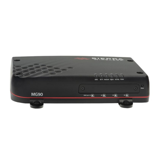
Page 8: Description
Introduction to the MG90 Description Antenna Connectors (See Connect the Antennas page 18.) GNSS Cellular A / Diversity A Wi-Fi A (Wi-Fi WAN) Bluetooth Cellular B / Diversity B Wi-Fi B (Wi-Fi Access Point) (1/2/3) (1/2/3) Back Panel Reprogram/Reset Ground RJ45 Ethernet Ports Locking USB 3.0 type-A Ports (See... -
Page 9: Power Modes
AirLink MG90 Hardware User Guide Power Modes The Sierra Wireless MG90 has two power modes, as described in Table 1-1. Table 1-1: MG90 Power Modes Power Consumption Mode Description Configuration 1 Cellular radio 14 W 17 W Ignition on, CPU and radios are on... -
Page 10: Warranty
Introduction to the MG90 Table 1-2: MG90 Accessories (Continued) Part Part Number Description Contact Sierra Wireless Optional Bluetooth antenna with Antenna for Bluetooth Sales for options. SMA connector Mounting bracket for easy vehicle Mounting bracket 6001024 installation and removal RS-232 GPIO breakout cable. See... -
Page 11: 2: Installation And Startup
Vehicle Wi-Fi access point (AP) broadcasting its own Serial Number as the SSID (e.g. ND60510068011018) · Ethernet—Ethernet ports 1–4 (factory default configured for LAN access) Refer to the AirLink MG90 Software Configuration Guide for configuration/usage instructions. Rev 3 Feb.17 4118699... -
Page 12: Tools And Materials Required
9 for suggested antennas. • SMA wrench (provided with MG90) • AC or DC power cable (available from Sierra Wireless or use your own custom cable). See Table 1-2 on page 9 for part numbers. • Optional—9-pin connection cable for the RS-232 port Caution: The MG90 has a hardened case for use in extreme environments. - Page 13 AirLink MG90 Hardware User Guide If you are using only one SIM card for a radio module, Sierra Wireless recommends that you install it in the module’s ‘1’ slot (e.g. SIM Card A1, SIM Card B1). If the SIM card(s) are not already installed, insert them into the MG90 before connecting any external equipment or power to the unit.
-
Page 14: Step 2-Mounting And Grounding The Mg90 Chassis
Installation and Startup Step 2—Mounting and Grounding the MG90 Chassis The MG90 should not be mounted in the driver’s area of the vehicle or in areas where it can distract the driver. Mount it in accordance with accepted after-market practices and materials. -
Page 15: Flat Surface Mount
AirLink MG90 Hardware User Guide Note: When mounting on a an inclined/vertical surface without the optional mounting bracket, the MG90 should be positioned with the antenna ports facing down (or sideways) with the mounting slots resting on mounting posts, as shown in Figure 2-3. -
Page 16: Bracket Mount
Installation and Startup Bracket Mount An optional mounting bracket (Part #6001024) is available from Sierra Wireless for vertical mounting. This bracket comes is supplied with appropriate mounting screws. Bracket orientation for 218.0 horizontal mounting 173.3 156.8 Vehicle mounting holes Green: Horizontal mount Blue: Vertical mount 96.3... -
Page 17: Ground The Mg90 Chassis
AirLink MG90 Hardware User Guide Ground the MG90 Chassis For DC installations (with a fixed “system” ground reference), Sierra Wireless strongly recommends always grounding the MG90 chassis to this system ground reference. To ensure a good grounding reference connect one end of a short 18 AWG or larger gauge wire with a ring terminal connector to the ground terminal on the rear panel of the MG90 and connect the other end to the vehicle chassis. -
Page 18: Step 3-Connect The Antennas
Installation and Startup When installing cables, adhere to the following practices: 1. Label each cable that attaches to the MG90. For example: “GNSS”, “Wi-Fi A”, “Ethernet to Device X”. 2. Protect the cables using a proper cable conduit. 3. Secure each cable connected to the MG90 via a permanent fixture. Step 3—Connect the Antennas Warning: This router is not intended for use close to the human body. - Page 19 AirLink MG90 Hardware User Guide For regulatory requirements concerning antennas, see Maximum Antenna Gain page 47. To install the antennas: 1. Mount the antenna unit(s) on the vehicle (typically multi-element units): · Follow the antenna unit’s recommended installation instructions. ·...
-
Page 20: Step 4-Connect The Data Cables
Installation and Startup Step 4—Connect the Data Cables The MG90 has multiple ports for connecting optional data cables or accessories: • Ethernet (10/100/1000 Base-T RJ45) ports (5) Use Cat 5e or Cat 6 Ethernet cables to connect up to five devices. ·... -
Page 21: Fusing
For more information, refer to the MG90 Software Configuration User Guide. Fusing For DC installations, Sierra Wireless recommends fusing the power input using a 9 A, fast blow fuse, recommended to have no more than ± 10% de-rating over the operating temperature range. -
Page 22: Connect The Router To The Vehicle's Electrical System
Type Note: If you want to turn the MG90 on/off using a control line, such as a vehicle ignition line, Sierra Wireless strongly recommends that you connect the control/ Power ignition line to Pin 3 and apply continuous power on Pin 1. -
Page 23: Wiring Diagrams
Grounding the MG90 Chassis on page 14. • Pin 3 (Ignition Sense) —Sierra Wireless recommends always using the Ignition Sense wire (Pin 3) to turn the router off. It should not be turned off by discon- necting the power. •... -
Page 24: I/O Configuration
Installation and Startup I/O Configuration The MG90 has five pins you can use for digital input configuration (digital output to be supported by a future software update): • Pin 4 on the power connector • Pins 1, 4, 6, and 9 on the RS-232 serial connector RS-232 Connector DC Power Connector Figure 2-11: I/O Pin-out for RS-232 Connector and Power Connector... -
Page 25: Step 6-Check The Router Operation
AirLink MG90 Hardware User Guide Table 2-3: Digital Input Pull-up State Minimum Typical Maximum Units — — High a. Voltage levels are compatible with 3.3V TTL standard logic families. High Side Pull-up / Dry Contact Switch Input You can connect any of the GPIO pins to a dry contact switch, such as an alarm relay. -
Page 26: Led Behavior
Installation and Startup Locking connector Figure 2-14: Power Cable Locking Connector 2. When power is supplied to the MG90, it powers up automatically. If it does not turn on, make sure that the: · Power connector is plugged in and supplying voltage greater than 11 V. Note: Although the MG90 operates in the range 7 V–36 V, low voltage standby mode is enabled by default, so in order to avoid the router powering on in standby mode, ensure that it is supplied with more than 11 V at startup. - Page 27 AirLink MG90 Hardware User Guide Table 2-5: LED Behavior (Continued) Color / Pattern Description Solid Green Wi-Fi enabled (any mode), and not connected to an access point Flashing Green Transmitting/receiving over Wi-Fi while not connected to an access point Wi-Fi connected to an access point (i.e. Network state is “Network Ready -...
-
Page 28: Ethernet Leds
Installation and Startup Ethernet LEDs The connector has two LEDs that indicate speed and activity. When looking into the connector: • Activity—The right LED indicates the link status: · Solid Amber—Link · Blinking Amber—Activity · Off—No link • Connection Speed—The left LED indicates the Ethernet connection speed: ·... -
Page 29: Reboot The Mg90
AirLink MG90 Hardware User Guide · If you make any configuration changes on a screen, you must click Save to save and apply them before changing screens. If you do not click Save, your changes will be lost. 5. When finished configuring the MG90, click the Logout tab to return to the login screen. -
Page 30: 3: Specifications
3: Specifications This chapter describes the MG90 router specifications, RF band and Tx power specifications, Wi-Fi support, and mechanical specifications. Router Specifications The following table describes general router specifications. Table 3-1: General Router Specifications • Certification and Emissions/Immunity CE (Including EMC Test case for vehicle installation EN301489) Interoperability •... - Page 31 AirLink MG90 Hardware User Guide Table 3-1: General Router Specifications (Continued) Environmental Vibration (operational) MIL-STD-810G, test methods 514.6, 527 Testing Composite Wheeled Vehicle Shock (operational) MIL-STD-810G, test method 516.6-I Procedure I—Functional Shock • SAE J1455 (Shock and Vibration: Section 4.10.4.2 Cab Mount Vibration) for heavy-duty •...
- Page 32 Specifications Table 3-1: General Router Specifications (Continued) Note: Do not use the USB ports in a potentially explosive environment. • USB 3.0 Type A port, complies with USB Version 3.0 specifi- cation • Port supports use of SeaLATCH Type A USB locking connectors Figure 3-1: USB Type A Locking Connector •...
- Page 33 AirLink MG90 Hardware User Guide Table 3-1: General Router Specifications (Continued) • Serial Port 9-pin RS-232 serial port configured as DTE, connects directly to most computers or other devices with a null-modem cable with handshaking Note: If you have a DTE device, you need to use a null modem (cross-over) cable with handshaking.
- Page 34 Specifications Table 3-1: General Router Specifications (Continued) Input / Output GPIOs: • Configurable I/O pin on power connector • GPIOs (4)—Connector type: RS-232 DB9 serial connector (see Serial Port on page 33) Uses: • Digital input with optional pullup (see Digital Input on page 24) •...
- Page 35 AirLink MG90 Hardware User Guide Table 3-1: General Router Specifications (Continued) • Conducted Electrical Transients Compliant to ISO 7637-2:2004: · Load dump specifications—Test Pulses 1, 5a, 5b · Harness transient specifications—Test Pulses 2a, 2b, 3a, 3b · Cranking specification—Test Pulse 4 •...
-
Page 36: Radio Bands/Conducted Tx Power
Specifications Table 3-1: General Router Specifications (Continued) • Security Secure all data WLAN Security and Authentication transmitted to and from · WEP, WPA, WPA2 vehicle without need for · Key management WPA-PSK and WPA-EAP VPN client software on • Firewall devices. -
Page 37: Sku 1102695/1102716 (North America/Europe)
AirLink MG90 Hardware User Guide SKU 1102695/1102716 (North America/Europe) The following tables indicate supported radio frequency bands and conducted transmit power specifications for SKU #1102695 and #1102716. Table 3-4: Supported Bands (SKU #1102695 / 1102716) Radio Band Frequency (Tx) Frequency (Rx) - Page 38 Specifications Table 3-5: Conducted Tx Power (SKU #1102695 / 1102716) Band Conducted Tx Notes Power (dBm) Bands 1, 2, 3, 4, 5, 8, 12, 13, 20, 25, 26 +23±1 Bands 7, 30, 41 +22±1 UMTS Band 1 (IMT 2100 12.2 kbps) Band 2 (UMTS 1900 12.2 kbps) Band 3 (UMTS 1800 12.2 kbps) +23±1...
-
Page 39: Sku 1103007 (North America)
AirLink MG90 Hardware User Guide SKU 1103007 (North America) The following tables indicate supported radio frequency bands and conducted transmit power specifications for SKU #1103007. Table 3-7: Supported Bands (SKU #1103007) Radio Band Frequency (Tx) Frequency (Rx) Technology Band 1 1920–1980 MHz... - Page 40 Specifications Table 3-8: Conducted Transmit Power (SKU #1103007) Band Conducted Tx Notes Power (dBm) Bands 1, 2, 3, 4, 5, 8, 12, 13, 20, 25, 26 +23±1 Bands 7, 30, 41 +22±1 Band 14 +23±2 UMTS Band 1 (IMT 2100 12.2 kbps) Band 2 (UMTS 1900 12.2 kbps) Band 3 (UMTS 1800 12.2 kbps) +23±1...
-
Page 41: Sku 1103239/1103240 (Asia/Pacific)
AirLink MG90 Hardware User Guide SKU 1103239/1103240 (Asia/Pacific) The following tables indicate supported radio frequency bands and conducted transmit power specifications for SKU #1103239 and #1103240. Table 3-10: Supported Bands (SKU #1103239/1103240) Radio Band Frequency (Tx) Frequency (Rx) Technology Band 1 1920–1980 MHz... - Page 42 Specifications Table 3-11: Conducted Tx Power (SKU #1103239/1103240) (Continued) Band Conducted Tx Notes Power (dBm) UMTS Band 1 (IMT 2100 12.2 kbps) Band 5 (UMTS 850 12.2 kbps) Band 6 (UMTS 850 12.2 kbps) +23±1 Connectorized (Class 3) Band 8 (UMTS 900 12.2 kbps) Band 9 (UMTS 1700 12.2 kbps) Band 19 (AWS 850 12.2 kbps) TD-SCDMA...
-
Page 43: Carrier Aggregation Combinations
AirLink MG90 Hardware User Guide Carrier Aggregation Combinations LTE-Advanced uses carrier aggregation to increase bandwidth. Table 3-13 Table 3-14 indicate supported carrier aggregation combinations. Table 3-13: Supported LTE Carrier Aggregation Combinations (SKU #1102695 / 1102716/1103007) 1 + 8 2+ 2/5/12/13/29... -
Page 44: Wi-Fi Support
Specifications Wi-Fi Support The MG90 includes two Wi-Fi modules: • Wi-Fi A · Default configuration—Wi-Fi WAN Instead of submitting data over cellular while in the field, the user can choose to wait until the vehicle arrives at its depot, where it can connect to the local access point. -
Page 45: Mechanical Specifications
AirLink MG90 Hardware User Guide Mechanical Specifications Top view Mounting holes LEDs Back view Front view Side view Weight 5.3 lb / 2.4 kg Figure 3-3: MG90 Mechanical Specifications Rev 3 Feb.17 4118699... -
Page 46: 4: Regulatory Information
• Consult the dealer or an experienced radio/TV technician for help. Warning: Changes or modifications to this device not expressly approved by Sierra Wireless could void the user's authority to operate this equipment. RF Exposure In accordance with FCC/IC requirements of human exposure to radio frequency fields, the radiating element shall be installed such that a minimum separation distance of 20 cm should be maintained from the antenna and the user's body. - Page 47 N7NMC7455 / 2417C-MC7455 UMTS PKTPEMAMW1 Sierra Wireless hereby declares the Sierra Wireless MG90 device is in compliance with the essential requirements and other relevant provisions of Directive 1999/5/EC. The MG90 displays the CE mark. Warning: Changes or modifications to this device not expressly approved by Sierra Wireless could void the user's authority to operate this equipment.
-
Page 48: Battery Replacement/Disposal
WEEE Notice If you purchased your Sierra Wireless MG90 in Europe, please return it to your dealer or supplier at the end of its life. WEEE products may be recognized by their wheeled bin label on the product label. -
Page 49: A: Accessories
A: Accessories Antenna Separation When installing single-element antenna units, refer to the following table for recommended antenna separation distances. Table A-1: Recommended Antenna Separation Antenna Separation Best (= 1/2 (mm) Good (= 1/4 (mm) Service Frequency (MHz) Wavelength ((mm) 1700 1800 1900 2100... -
Page 50: Gpio Breakout Cable
Accessories GPIO Breakout Cable The GPIO breakout cable provides access to four GPIOs via pins 1, 4, 6, 9. 2940 ± 50 Cables unterminated Pin 5 Pin 1 Pin 9 Pin 6 Figure A-1: GPIO Breakout Cable Table A-2: GPIO Breakout Cable Part Number 6001095 Product Release Date...
Need help?
Do you have a question about the Airlink MG90 and is the answer not in the manual?
Questions and answers