Table of Contents
Advertisement
Advertisement
Table of Contents

Related Manuals for Sierra Wireless AirLink RX55


Summary of Contents for Sierra Wireless AirLink RX55
- Page 1 AirLink RX55 Hardware User Guide 41114494 Rev. 1 September 2022...
- Page 2 Sierra Wireless accepts no responsibility for damages of any kind resulting from delays or errors in data transmitted or received using the Sierra Wireless product, or for failure of the Sierra Wireless product to transmit or receive such data.
- Page 3 Sierra Wireless product. Patents This product may contain technology developed by or for Sierra Wireless Inc. This product ® includes technology licensed from QUALCOMM .
- Page 4 AirLink RX55 Hardware User Guide ® QUALCOMM is a registered trademark of QUALCOMM Incorporated. Used under license. Other trademarks are the property of their respective owners. Contact Information Sales information and technical Web: sierrawireless.com/company/contact-us/ support, including warranty and returns Global toll-free number: 1-877-687-7795...
-
Page 5: Table Of Contents
Introduction to the AirLink RX55 ........ - Page 6 AirLink RV55 Hardware User Guide Step 5—Connect the Power ..........25 Cable Strain Relief .
- Page 7 Contents Radio Frequency Bands ..........52 Carrier Aggregation Combinations.
-
Page 8: Introduction To The Airlink Rx55
1: Introduction to the AirLink RX55 ® ® The Sierra Wireless AirLink RX55 LTE-A router is a compact, intelligent and fully- featured communications platform that provides real-time wireless capabilities for fixed and mobile applications. It is intended for use in industrial settings such as: •... -
Page 9: Description
Introduction to the AirLink RX55 • Multi-function digital input, analog input, switchable low side current sink, and high side configurable pull-up Description Back Panel Cellular Antenna Connector Cellular Antenna Connector 9-pin RS-232 Serial Port (See Connect the Antennas (See Connect the Antennas page 20.) -
Page 10: Router Configuration And Management
Sierra Wire- less distributor. Power Modes The AirLink RX55 router has two power modes: • Idle Connected—The CPU and the radio are on. • Standby—The CPU and the radio are off, but can be woken by an I/O input or at a configured time. -
Page 11: Power Saving Features
Introduction to the AirLink RX55 Power Saving Features Table 1-2 provides a quick reference to the ways you can save power with the RX55. Table 1-2: Power Saving Features Feature Where to configure Notes in AirLink OS Processor Power System > MCU >... -
Page 12: Sample Power Consumption Scenarios
AirLink RX55 Hardware User Guide Table 1-2: Power Saving Features (Continued) Feature Where to configure Notes in AirLink OS Standby (Time-based) System > MCU > The RX55 router is in standby mode and automatically wakes Voltage Threshold up periodically, for example hourly or daily. -
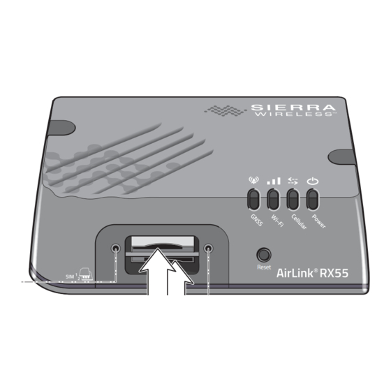
Page 13: Dual Sim
Introduction to the AirLink RX55 Dual SIM The AirLink RX55 router has two SIM card 2FF slots. You can configure which slot is the Primary SIM card—by default, the upper SIM slot is for the Primary SIM card. To configure the Primary and Secondary SIM card slots, see Hardware Interfaces > Cellular Interfaces >... -
Page 14: Warranty
AirLink RX55 Hardware User Guide Warranty You can download the RX55 router warranty from the Sierra Wireless Source. Click sign up to register for free. Rev. 1 September 2022 41114494... -
Page 15: Installation And Startup
2: Installation and Startup This chapter shows how to connect, install and start the Sierra Wireless RX55 router. It also describes the front panel LEDs, and I/O functionality. Note: Field wiring and connections in hazardous locations must be connected as per the wiring methods requirement for Class 2 circuits mentioned in the National Electric Code and the Canadian Electric Code. -
Page 16: Step 1-Insert The Sim Cards
Slot 2. AirLink OS references these slot numbers, and by default, the SIM card in Slot 1 is the Primary SIM card. If you are using only one SIM card, Sierra Wireless recommends that you install it in Slot 1. -
Page 17: Step 2-Mounting And Grounding The Rx55 Router
Mounting Brackets The RX55 router comes with mounting screws. An optional DIN rail mounting bracket (P/N 6000659) is available from Sierra Wireless. Flat Surface Mount If you are mounting the RX55 router on a flat surface, use the mounting screws that come with the router. -
Page 18: Din Rail Mount
Figure 2-2: RX55 Router Mounting Hole Locations and Dimensions DIN Rail Mount If you are mounting the RX55 router on a DIN rail, order DIN rail mounting bracket kit (P/N 6000659) from Sierra Wireless. The kit contains: • L-shaped DIN Rail Mounting Bracket—Qty 1 •... -
Page 19: Grounding The Rx55 Router Chassis
Power Consumption Scenarios on page 12. Note: The DIN rail mounting bracket and clip in the Sierra Wireless kit should only be used on horizontally-mounted DIN rail. Grounding the RX55 Router Chassis For DC installations (with a fixed “system” ground reference), you must ground the RX55 chassis to this system ground reference. -
Page 20: Step 3-Connect The Antennas
AirLink RX55 Hardware User Guide • Connect one end of a short 18 AWG or larger gauge wire to the unpainted upper left mounting hole (see Figure 2-2) and connect the other end to the system ground reference or (if mounted in a vehicle) the vehicle chassis. - Page 21 Installation and Startup To install the antennas: 1. Connect the cellular antenna to the SMA cellular antenna connector. Mount the cellular antenna so there is at least 20 cm between the antenna and the user or bystander. 2. Connect a second antenna to the SMA Cellular 2 antenna connector. 3.
-
Page 22: Recommended Antenna Separation
The recommended antenna separation is related to the band frequency/wavelength. To accommodate the shortest frequency/longest wavelength band supported by the RX55, Sierra Wireless recommends a minimum antenna separation of 214 mm for best results, and if necessary, a separation of 107 mm for acceptable results. -
Page 23: Usb Port
The same serial port can be configured as a dual 4-wire serial port, and connect to devices with a Y cable (Sierra Wireless part number 6001238). The Dual Port Mode setting is available in AirLink OS under Hardware Interfaces > Serial > Configuration >... - Page 24 AirLink RX55 Hardware User Guide Figure 2-5: DB-9 Female Serial Connector Table 2-2: Serial Connector Pin-out (Single Port Mode) Name Description Type Data Carrier Detect Receive Data Transmit Data Data Terminal Ready Main GND. Connected internally to BOARD GND Data Set Ready...
-
Page 25: Step 5-Connect The Power
Installation and Startup Step 5—Connect the Power The AirLink RX55 router comes with a 3 meter (10 ft.) DC power cable. You can also purchase an optional AC adapter. Note: Electrical installations are potentially dangerous and should be performed by personnel thoroughly trained in safe electrical wiring procedures. -
Page 26: Power Connector On The Rx55 Router
AirLink RX55 Hardware User Guide Power Connector on the RX55 Router White Pin 3 Ignition Sense Ignition switch or external Green solar power low voltage Pin 4 disconnect device GPI/O Pin 1 Optional: Connect Power to switch, relay or external device... - Page 27 Wire Color Ignition White Sierra Wireless recommends using the Ignition Sense wire to turn the router Sense off. It should not be turned off by disconnecting the power. Note: If you do not connect pin 3 to the ignition, you MUST connect it to the positive terminal of your power supply or battery.
-
Page 28: Wiring Diagrams
Pin 1 (Power) —Use the red wire in the DC cable to connect Pin 1 to the power source. Include a 4.0 A fast-acting fuse in the input power line. Sierra Wireless recom- mends using a continuous (unswitched) DC power source. - Page 29 Pin 1 (Power) —Use the red wire in the DC cable to connect Pin 1 to the power source. Include a 4.0 A fast-acting fuse in the input power line. Sierra Wireless recom- mends using a continuous (unswitched) DC power source.
-
Page 30: I/O Configuration
Pin 1 (Power) —Use the red wire in the DC cable to connect Pin 1 to the power source. Include a 4.0 A fast-acting fuse in the input power line. Sierra Wireless recom- mends using a continuous (unswitched) DC power source. - Page 31 Installation and Startup Note: During bootup, the I/O settings remain in their default state: the internal pull-up resistor is disabled, and output current sink switch is open. After bootup, any custom I/O settings are applied. This may take approximately 30 seconds after the router is restarted or powered on. You can use Pin 4 in conjunction with Telemetry to configure the RX55 router to send a report when the state of the monitored router changes, for example when a switch is opened or closed.
- Page 32 AirLink RX55 Hardware User Guide Digital Input You can use the green wire to connect Pin 4 to a digital input to detect the state of a switch such as a vehicle ignition, or to monitor an external device such as a motion detector, a remote solar panel, or a remote camera.
- Page 33 Installation and Startup High Side Pull-up / Dry Contact Switch Input You can use the green wire to connect Pin 4 to a dry contact switch. The dry contact switch is not available in Standby mode. RX55 Internal pull-up resistor (10K) Pin 4 (power connector) On** = 1.1 mA (Typ)
- Page 34 AirLink RX55 Hardware User Guide Analog Input You can use the green wire to connect Pin 4 to an analog sensor. As an analog input (voltage sensing pin), the router monitors voltage changes in small increments. This allows you to monitor equipment that reports status as an analog voltage.
- Page 35 Installation and Startup Note: The same method is used to sample the input voltage and the internal board temperature for Events Reporting. The significant changes are 300 mV for the input voltage and 1 ºC for the board temperature. Low Side Current Sink Output You can use Pin 4 as a low side current sink, for example, to drive a relay.
-
Page 36: Step 6-Check The Router Operation
— Step 6—Check the Router Operation 1. When power is supplied to the AirLink RX55 router, it powers up automatically, as indicated by the flashing LEDs. If it does not turn on, ensure that the: · Power connector is plugged in and supplying voltage between 7–36 V. -
Page 37: Led Behavior
Installation and Startup LED Behavior Figure 2-18: RX55 LEDs LED Patterns The RX55’s LEDs display four device statuses (see Table 2-11)—GNSS, Wi-Fi, Cellular radio, and Power using a variety of pattern types and colors: • Solid—Single color, always on • Fast flashing—One color on for 0.2 s, then off or another color for 0.2 s •... - Page 38 AirLink RX55 Hardware User Guide Table 2-11: LED Behavior (Continued) Wi-Fi Solid Green (pulse off with activity) Connected in Client mode (good signal) with traffic Connected in Access Point mode with traffic (Client mode not configured) Note: If access point and client are configured and have traffic at same time, LED displays the client status (i.e. displaying a connected Depot is the priority).
- Page 39 Installation and Startup Table 2-11: LED Behavior (Continued) Fast Flashing Green Router is rebooting after Reset button pressed for <5 seconds (or reset from AirLink OS) Solid Yellow Router is booting • Router is thermally throttled—one or more of CPU, cellular radio, and Wi-Fi radio has exceeded threshold. When operating temperature •...
-
Page 40: Ethernet Leds
AirLink RX55 Hardware User Guide Ethernet LEDs The Ethernet connector has two LEDs that indicate speed and activity. When looking into the connector: • Activity—The right LED is solid amber when a link is present and flashing amber when there is activity. -
Page 41: Step 7-Startup And Software Configuration
Installation and Startup Step 7—Startup and Software Configuration You can configure the AirLink OS software on the RX55 router using: • Web-based UI • AirLink Management Service (cloud-based application) Configuring with AirLink OS You can configure the RX55 using: • AirLink OS (the RX55’s web interface) •... -
Page 42: Configure And Monitor Remotely With Airlink Management Service
AirLink RX55 Hardware User Guide Configure and Monitor Remotely with AirLink Management Service AirLink Management Service (ALMS) allows remote management of all your routers from one user interface. Some of its features include: • Centralized, remote monitoring for all your AirLink routers •... - Page 43 Installation and Startup Tip: In AirLink OS, you can configure the RX55 router to revert to a custom settings template when the router is reset to the factory default settings. See the RESET CONFIGURATION TYPE list in AirLink OS ( System >...
-
Page 44: Specifications At A Glance
3: Specifications at a Glance This chapter provides the specifications for the RX55 router. Certification and Interoperability Emissions / Immunity • ISED Canada • Safety CB Scheme • UL 62368-1 • Industry Certification E-Mark (UN ECE Regulation 10.04), ISO7637-2 • for Vehicles SAE J1455 (Shock &... -
Page 45: Reliability Specifications
Specifications at a Glance Test Method Category Description MIL-STD-810G, Humidity 10 × 48-hour cycles: Test method 507.5 4-hour ramp to 60 °C (95% humidity), hold 8 hours • 4-hour ramp down to 30 °C (85% to 95% relative • humidity), hold 21 hours 1-hour ramp down to 20 °C, hold 4 hours •... -
Page 46: Included Radio Module Firmware
By default, the USB port is configured as a virtual Ethernet port. A Windows driver must be installed on the PC in order to support USB • use. The drivers are available for download on Sierra Wireless’ support web site: source.sierrawireless.com/resources/airlink/software_downloads/... -
Page 47: Sim Card Interface
Specifications at a Glance Ethernet 10/100/1000 Base-T RJ-45 Ethernet • IEEE 802.3 Ethernet specification for 1000 Mbps speed (Gigabit • Ethernet) with fallback to 100 or 10 Mbps (Cat 5e or Cat 6 cable is required for Gigabit Ethernet) Auto-crossover support •... -
Page 48: Operating Voltage
The device looks for a qualified voltage on this pin as part of the power up sequence. If it doesn’t see it, the device will not turn on. If you are using a Sierra Wireless AC power adapter, the connection is inside the cable. -
Page 49: Gnss Bands Supported
Specifications at a Glance Table 3-3: GNSS Specifications (Continued) Parameter/feature Description Tracking : -160 dBm Sensitivity Acquisition (Assisted): -158 dBm Acquisition (Standalone): -145 dBm Altitude <18288 m (60,000 ft), or Velocity <1852 km/h (1000 knots) Operational limits (Either limit may be exceeded, but not both.) a. -
Page 50: Protocols
AirLink RX55 Hardware User Guide Protocols • Network: TCP/IP, UDP/IP, DNS • Routing: NAT, Host Port Routing, DHCP, PPPoE, VLAN, VRRP, Reliable Static Route • Applications: SMS, Telnet/SSH, Reverse Telnet, SMTP, SNMP, SNTP • Serial: TCP/UDP PAD mode, Modbus (ASCII, RTU, Variable), PPP •... -
Page 51: Wi-Fi Antenna Gain
Wi-Fi Antenna Gain The AirLink RX55 is compliant with the RF exposure requirements at 20 cm separation distance specified in EN 62311:2008 and 1999/519/EC for mobile exposure conditions, provided the maximum antenna gain does not exceed the limits given in the table below. -
Page 52: Radio Frequency Bands
AirLink RX55 Hardware User Guide Radio Frequency Bands Use the following table as a guide to the radio frequencies and transmit power supported by the RX55 radio modules. To determine which radio module your router has, refer to the label on the bottom of the... - Page 53 Specifications at a Glance Note: Values in the following table are preliminary, pending transceiver matching/testing. Table 3-9: EM7411 Conducted Tx (Transmit) Power Tolerances Bands Conducted Tx power Notes LTE bands 2, 4, 25, 26, 66 22.5 dBm 1 dB ...
-
Page 54: Carrier Aggregation Combinations
AirLink RX55 Hardware User Guide Table 3-11: EM7421 WCDMA Frequency Bands Support Frequency (Tx) Frequency (Rx) Band Band 1 1920–1980 MHz 2110–2170 MHz Band 5 824–849 MHz 869–894 MHz Band 8 880–915 MHz 925–960 MHz Table 3-12: EM7421 Conducted Tx (Transmit) Power Tolerances... - Page 55 Specifications at a Glance Table 3-13: EM7411 Carrier Aggregation Downlink Combinations 1 Band / 2CC 2 Bands / 2CC CA_4A-4A CA_4A-5A CA_4A-7A CA_4A-12A CA_4A-13A CA_4A-71A CA_5B CA_5A-66A CA_7A-7A CA_7A-12A CA_7B CA_7C CA_12B CA_12A-66A CA_13A-66A CA_14A-66A CA_25A-25A CA_25A-26A CA_26A-41A CA_41A-41A CA_41C CA_42A-42A CA_42C CA_43C...
- Page 56 AirLink RX55 Hardware User Guide Table 3-14: EM7421 Carrier Aggregation Downlink Combinations 1 Band / 2CC 2 Bands / 2CC CA_3A-3A CA_3A-7A CA_3C CA_3A-8A CA_3A-20A CA_3A-28A CA_7A-7A CA_7A-8A CA_7B CA_7A-20A CA_7C CA_7A-28A CA_20A-32A CA_38C CA_40A-40A CA_40C CA_41A-41A CA_41C CA_42A-42A CA_42C CA_43C Rev.
-
Page 57: Mechanical Specifications
Specifications at a Glance Mechanical Specifications • Housing—The RX55 router is made of ruggedized powder-coated aluminum. • RoHS—The RX55 router complies with the Restriction of Hazardous Substances Directive (RoHS). This directive restricts the use of six hazardous materials in the manufacture of various types of electronic and electrical equipment. -
Page 58: Screw Torque Settings
AirLink RX55 Hardware User Guide Screw Torque Settings • DIN rail mount screws: 1.1 N-m (10 in-lb) • Antennas: Finger tight (5–7 in-lb) is sufficient. The max torque should not go beyond 1.1 N-m (10 in-lb). Rev. 1 September 2022... -
Page 59: Regulatory Information
RF radiation, the maximum antenna gain must not exceed the specifications listed below for the device used. Sierra Wireless hereby declares the AirLink RX55 devices are in compliance with the essential requirements and other relevant provisions of Directive 2014/53/EU. -
Page 60: Iecex Compliance
AirLink RX55 Hardware User Guide Declaration of Conformity The Declaration of Conformity made under Directive 2014/53/EU is available for viewing at: source.sierrawireless.com/resources/airlink/certification_and_type_approval/ RX55_ce_declaration_of_conformity/ IECEx Compliance Special condition of safe use: • Equipment shall be installed in an Ex certified tool secured enclosure which provides a minimum ingress protection of IP54. -
Page 61: Weee Notice
Regulatory Information WEEE Notice If you purchased your AirLink RX55 device in Europe, please return it to your dealer or supplier at the end of its life. WEEE products may be recognized by their wheeled label on the product label. -
Page 62: Accessories
A: Accessories DC Power Cable (Black Connector) Table A-1: DC Power Cable DC Power Cable Part Number 2000522 Product Release 2016 Components: 1 UL2464 20 AWG × 4 core cable 4 Molex female crimp terminals /AWG 20-24, 250 V, 4 A Max, phosphor bronze tin-plated (part number 43030-0001) ... -
Page 63: Ac Power Adapter (Black Connector)
Accessories AC Power Adapter (Black Connector) Note: Please note that the AC power adapter is not available for sale in New Zealand (as of June 1, 2018). AC Power Adapter Part Number 2000579 Product Release Date 2016 AC Power Adapter Input Table A-2: Input Specifications Minimum Typical... -
Page 64: Ac Power Adapter Environmental Specifications
AirLink RX55 Hardware User Guide AC Power Adapter Environmental Specifications Table A-4: AC Power Adapter Environmental Specifications Operating Operating Temperature 0°C ~ 40°C (operates normally) Relative Humidity 10% ~ 90% Altitude Sea level to 2,000 meters Vibration 1.0 mm, 10–55 Hz, 15 minutes per cycle for each axis... -
Page 65: Ac Power Adapter Emc Standards
Accessories AC Power Adapter EMC Standards The power supply meets the radiated and conducted emission requirements for EN55022, FCC Part 15, Class B, GB9254. AC Power Adapter Hazardous Substances • EU Directive 2011/65/EU “RoHS” • EU Directive 2012/19/EU “WEEE” • REACH AC Power Adapter Energy Efficiency The AC adapter complies with International Efficiency Levels, as shown in... -
Page 66: Dual Serial Port Adapter Cable
AirLink RX55 Hardware User Guide Dual Serial Port Adapter Cable Dual Serial Port Adapter Cable Part Number 6001238 Product Release 2019 Pin 1 Port 1 Pin 1 Port 3 Pin 1 Pin 9 Port 2 Pin 9 Pin 9 Table A-7: Serial Connector Pin Assignment... -
Page 67: Serial Can Y-Cable
Accessories Serial CAN Y-Cable The Serial CAN Y-Cable allows you to connect the RX55 to another serial-based system and/or to a vehicle bus interface cable. Serial CAN Y-Cable Part Number 6001479 Product Release 2022 DB9 Female— Accepts RS232 input Pin 1 from DB9 male DB9 Male—... -
Page 68: Index
Index Accessories, 13 Host Interfaces, 46 accuracy (GNSS), 48 ACEmanager, 10 acquisition time (GNSS), 48 AirLink Management Service, 10 I / O Configuration, 30 Analog input, 34 Input Antenna Analog, 34 Connecting, 20 Dry contact switch, 33 Recommended separation, 22 Ignition switch, 32 Safe... - Page 69 Index power tolerances, conducted Tx, 53, 54 Protocols, 50 Pull-up resistor, 33 Pulse counter, 31 Rebooting, 42 Regulatory information, 59 Regulatory specifications, 65 Reliability, 45 Reset to factory default settings, 42 RF bands supported LTE, 52, 53, 54 specifications, 20 Screw Torque, 58 Serial connector...
Need help?
Do you have a question about the AirLink RX55 and is the answer not in the manual?
Questions and answers