Table of Contents
Advertisement
Advertisement
Table of Contents

Related Manuals for Sierra Wireless AirLink MP70


Summary of Contents for Sierra Wireless AirLink MP70
- Page 1 AirLink MP70 Hardware User Guide 4119008 Rev 4...
- Page 2 Data may be delayed, corrupted (i.e., have errors) or be totally lost. Although significant delays or losses of data are rare when wireless devices such as the Sierra Wireless modem are used in a normal manner with a well-constructed network, the Sierra Wireless modem should not be used in...
-
Page 3: Contact Information
Sierra Wireless product, regardless of the number of events, occurrences, or claims giving rise to liability, be in excess of the price paid by the purchaser for the Sierra Wireless product. -
Page 4: Table Of Contents
Contents Introduction to the MP70 ......... .6 Key Features . - Page 5 Contents Reset the MP70 to Factory Default Settings ......30 Recovery Mode ..........31 Specifications .
-
Page 6: Introduction To The Mp70
1: Introduction to the MP70 The AirLink MP70 is a high performance, LTE Advanced vehicle router developed specifically for mobile mission-critical applications in public safety, transit, and field services. Offering high power, long range Gigabit Wi-Fi and Gigabit Ethernet, and up to 300... -
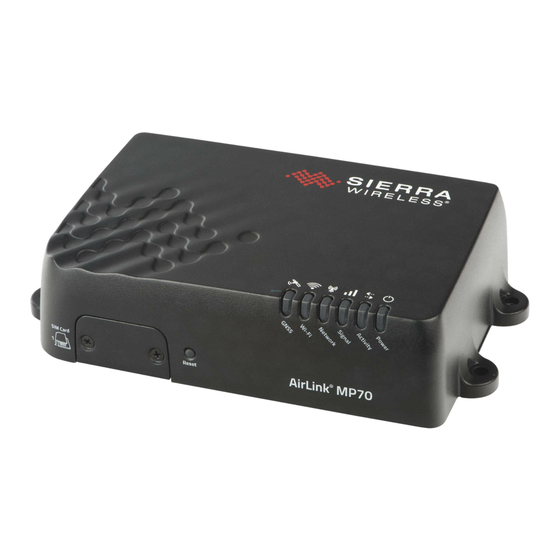
Page 7: Description
Introduction to the MP70 Description Diversity Antenna Connector Back Panel (See Connect the Antennas GNSS Antenna Connector page 12.) Cellular Antenna Connector Wi-Fi Antenna Connector Auxiliary I/O Ports (See Connect the Antennas (See I/O Pins on page 20.) page 12.) Power Connector USB 2.0 Micro-AB Port Four RJ-45 Ethernet Port... -
Page 8: Modes And Power Consumption
• DC power cable • Mounting screws • Quick Start Guide The following items can be ordered separately from Sierra Wireless: • Universal AC power adapter · Voltage input: 100–240 VAC · Current output: 1.5 A · Part number: 2000492 •... -
Page 9: Installation And Startup
2: Installation and Startup This chapter shows how to connect, install and start the Sierra Wireless MP70. It also describes the front panel LEDs, and I/O functionality. Note: Sierra Wireless recommends that a professional vehicle electronics installer perform the installation. An experienced installer typically completes a standard installation in approximately half an hour. -
Page 10: Step 1-Insert The Sim Cards
Step 1—Insert the SIM Cards The AirLink MP70 has two mini-SIM (2FF) card slots. The upper slot is Slot 1 and the lower slot is Slot 2. By default, the SIM card in Slot 1 is the Primary SIM card. -
Page 11: Step 2-Mount And Ground The Mp70 Chassis
The MP70 should not be mounted in the driver’s area of the vehicle or in areas where it can distract the driver. Mount it in accordance with accepted after-market practices and materials. Sierra Wireless strongly recommends that you always ground the chassis using the unpainted mounting hole shown if Figure 2-2. -
Page 12: Cabling Concerns
Separate MP70 antenna, data, and power cables from other wiring in the vehicle and route away from sharp edges. Cable Strain Relief Sierra Wireless recommends using cable strain relief for installations in high- vibration environments. Place the cable strain relief within 200 mm (8") of the MP70 to reduce the mass of cable supported by the power connector under vibration. - Page 13 If you are not using the second antenna, it can be disabled in ACEmanager, but Sierra Wireless recommends always using it, as disabling the second antenna prevents it being used in both the 3G and 4G applications.
-
Page 14: Recommended Antenna Separation
All components used in the electrical connection to the vehicle should be UL Listed. The AirLink MP70 comes with a 3 meter (10 ft.) DC power cable. You can also purchase an optional AC adapter. -
Page 15: Fusing
Installation and Startup Fusing For DC installations, Sierra Wireless recommends fusing the power input using a 7.5 A, fast blow fuse, recommended to have no more than +/- 10% de-rating over the operating temperature range. DC Voltage Transients The AirLink MP70 has built-in protection against vehicle transients including engine cranking (down to 5.0V) and load dump, so there is no need for external... -
Page 16: Connect The Router To The Vehicle's Electrical System
Note: If you do not connect pin 3 to the ignition, you MUST connect it to the positive terminal of your power supply or battery. If you are using a Sierra Wireless AC adapter, the connection is inside the cable. -
Page 17: Wiring Diagrams
Include a 7.5 A, fast blow fuse, recommended to have no more than +/- 10% de-rating over the operating temperature range, in the input power line. Sierra Wireless recommends using a continuous (unswitched) DC power source. Connect the power through the vehicle’s fuse box. -
Page 18: Fixed Installation
Pin 1 (Power) —Use the red wire in the DC cable to connect Pin 1 to the power source. Include a 7.5 A, fast blow fuse, recommended to have no more than +/- 10% de-rating over the operating temperature range, in the input power line. Sierra Wireless recommends using a continuous (unswitched) DC power source. •... -
Page 19: I/O Configuration
Pin 4 (GPIO)—Use the green wire for I/O configurations. See I/O Configu- ration on page 19. I/O Configuration The AirLink MP70 has five pins you can use for I/O configuration: • Pin 4 on the power connector • Pins 2, 3, 6, and 7 on the auxiliary I/O connector Rev 4 Nov.16... -
Page 20: I/O Pins
AirLink MP70 Hardware User Guide I/O Pins Power Connector Auxiliary I/O Connector DIGIN DIGIN DIGIN DIGIN a. Do Not Connect Figure 2-9: I/O Pin-out for Auxiliary I/O Connector and Power Connector Table 2-3: I / O Pin-out Configuration Location Pin — Wire... - Page 21 Installation and Startup You can use the I/O pins as: · Pulse counters (See Table 2-4 on page 22 and Figure 2-10 on page 22.) · digital inputs (See Table 2-4 on page 22 and Figure 2-11 on page 23.) ·...
-
Page 22: Digital Input
AirLink MP70 Hardware User Guide MP70 router Pin 4 on the power connector, or Internal Pull-up Pin 2, 3, 6, or 7 on the auxiliary Resistor I/O connector Off (default)* = 100 kΩ Digital Pulse Generator Protection circuitry ≤ 1.0 V ≥... - Page 23 Installation and Startup MP70 router Pin 4 on the power connector, or Internal Pull-up Pin 2, 3, 6, or 7 on the auxiliary Resistor I/O connector Off (default)* High ≥ 2.7 V Digital input Protection circuitry * Configurable on the ACEmanager I/O tab Figure 2-11: Digital Input Table 2-5: Digital Input Pull-up...
-
Page 24: Analog Input
AirLink MP70 Hardware User Guide Table 2-6: High Side Pull-up / Dry Contact Switch Input Minimum Typical Maximum Units Comments Source Current Maximum current the voltage output can provide (depends on Vin = 7 V Vin = 12 V Vin = 36 V Vin) - 2.5... - Page 25 Installation and Startup Data sampling is handled by a dedicated microprocessor. In order to filter noisy signals, twenty measurements are taken over a 250 ms interval and they are averaged to generate a sample. If the change since the last sample is significant, a notification is sent to the CPU for updating the current value displayed in the user interface and for use by Events Reporting.
-
Page 26: Step 6-Check The Router Operation
5 mA, Step 6—Check the Router Operation 1. When power is supplied to the AirLink MP70 router, it powers up automati- cally, as indicated by the flashing LEDs. If it does not turn on, ensure that the: · Power connector is plugged in and supplying voltage greater than 9 V. -
Page 27: Led Behavior
Flashing Red Inadequate (equivalent to 0 bars) Sierra Wireless recommends moving the router to a location with a better signal. Note: The quality of the signal strength is measured using the appropriate parameters for the radio technology in use. -
Page 28: Ethernet Leds
AirLink MP70 Hardware User Guide Table 2-10: LED Behavior Color / Pattern Description Network Solid Green Connected to an LTE network Solid Amber Connected to a 3G or 2G network Flashing Green Connecting to the network Flashing Red No network available... -
Page 29: Step 7-Configure The Software
Installation and Startup · Solid Orange—1000 Mbps (Gigabit) · Off—10/100 Mbps Step 7—Configure the Software You can configure the ALEOS software on the MP70 using: • ACEmanager (browser-based application) • AirLink Management Service (cloud-based application) • oMM Management System (unified software platform deployed in the enter- prise data center) •... -
Page 30: Reboot The Mp70
If you require a network management solution deployed in your data center, contact your Sierra Wireless sales representative for a demonstration of the oMM capabilities. Configuring with AT Commands For a complete list of AT commands, refer to the ALEOS Software Configuration User Guide. -
Page 31: Recovery Mode
Installation and Startup Note: When you reset the router to the factory default settings, some settings such the network ID, network password, custom APNs, Primary SIM, low voltage standby are preserved by default. However, you can configure the MP70 to reset all values. For more details, refer to the ALEOS Software Configuration User Guide (Admin chapter). -
Page 32: Specifications
3: Specifications This chapter describes the MP70 router specifications. Table 3-1: Specifications Certification and Emissions / CE (Including EMC Test case for vehicle installation EN301489) • Interoperability Immunity ACMA RCM • • Industry Canada • Safety CB Scheme • UL 60950 •... - Page 33 Specifications Table 3-1: Specifications (Continued) Environmental Vibration MIL-STD-810G, test method 514.6 Testing (operational) Composite Wheeled Vehicle Shock MIL-STD-810G, test method 516.6-I (operational) Procedure I—Functional Shock SAE J1455 (Shock Vibration: Section 4.10.4.2 Cab Mount • and Vibration) for Shock: Section 4.11.3.4 Operational Shock •...
- Page 34 AirLink MP70 Hardware User Guide Table 3-1: Specifications (Continued) Note: Do not use the USB port in a potentially explosive environment. USB 2.0 Micro-AB connector complies with USB Version 2.0 for • high speed operation Can be configured to operate in one of two modes: •...
- Page 35 Specifications Table 3-1: Specifications (Continued) Serial Port 9-pin RS-232 serial port connects directly to most computers or • other devices with a standard serial straight-through cable Note: If you have a DCE device, you need to use a null modem (cross-over) cable.
- Page 36 AirLink MP70 Hardware User Guide Table 3-1: Specifications (Continued) Power Adapter Pins 4-Pin connector: Power • Ground • Configurable digital I/O and analog voltage input sensing • Configurable ignition sense • Reset Manual reset button or using ACEmanager LEDs 6 LEDs: LED Behavior on page 27.
- Page 37 Specifications Table 3-1: Specifications (Continued) GNSS Satellite channels Maximum 48 tracking channels and 2 fast acquisition channels Technology Constellations • Galileo • GLONASS • BeiDou • QZSS • Protocol NMEA 0183 V3.0 Acquisition time Hot start: 1 second • (Time to first fix) Cold start: 30 seconds •...
-
Page 38: Wi-Fi Performance
AirLink MP70 Hardware User Guide Wi-Fi Performance Technology Frequency MIMO 20 MHz 40 MHz 80 MHz 802.11n 2.4 GHz 1 x 1 72 Mbps 2 x 2 144 Mbps 3 x 3 216 Mbps 5 GHz 1 x 1 72 Mbps... - Page 39 Specifications Table 3-3: MP70 Radio Module MC7455 North America and EMEA Radio Band Frequency (Tx) Frequency (Rx) Technology HSPA+ Band 1 1920 –1980 MHz 2110–2170 MHz Band 2 1850–1910 MHz 1930–1990 MHz Band 3 1710–1785 MHz 1805–1880 MHz Band 4 1710–1755 MHz 2110–2155 MHz Band 5...
-
Page 40: Radio Module Conducted Transmit Power
AirLink MP70 Hardware User Guide Table 3-5: GNSS Bands Supported Band Frequency 1575.42 MHz GLONASS 1602 MHz Galileo 1575.42 MHz BeiDou 1561.098 MHz QZSS 1176.45–1575.42 MHz Radio Module Conducted Transmit Power The following tables provide radio module conducted transmit power specifications. -
Page 41: Carrier Aggregation Combinations
Specifications Table 3-7: Radio Module MC7430 Conducted Transmit Power (Continued) Band Conducted Tx Notes Power (dBm) HSPA+ +23±1 Connectorized (Class 3) Band 1 (IMT 2100 12.2 kbps) Band 5 (UMTS 850 12.2 kbps) Band 6 (UMTS 800 12.2 kbps) Band 8 (UMTS 900 12.2 kbps) Band 9 (UMTS 1700 12.2 kbps) Band 19 (UMTS 850 12.2 kbps) TD-SCDMA... - Page 42 AirLink MP70 Hardware User Guide Table 3-9: MC7430 Carrier Aggregation Combinations (Continued) 8 + 1 18 + 1 19 + 1/3/21 21 + 1/19 28 + 3/7 38 + 38 39 + 39 40 + 40 41 + 41 Rev 4 Nov.16...
-
Page 43: Mechanical Specifications
Specifications Mechanical Specifications Weight: 0.76 Kg (1.68 lb.) Back view 190.03 mm 7.48 in. Front view 44.99 mm 1.77 in. Underside view 115.29 mm 4.54 in. 108.91 mm 4.29 in. Figure 3-2: MP70 Mechanical Specifications Rev 4 Nov.16 4119008... -
Page 44: Regulatory Information
• Consult the dealer or an experienced radio/TV technician for help. Warning: Changes or modifications to this device not expressly approved by Sierra Wireless could void the user's authority to operate this equipment. RF Exposure In accordance with FCC/IC requirements of human exposure to radio frequency fields, the radiating element shall be installed such that a minimum separation distance of 20 cm should be maintained from the antenna and the user's body. -
Page 45: Declaration Of Conformity
FCC ID/IC Number N7NMC7455 2417C-MC7455 Maximum Antenna Gain (dBi) AirLink MP70 Sierra Wireless hereby declares the AirLink MP70 device is in compliance with the essential requirements and other relevant provisions of Directive 1999/5/EC. The MP70 displays the CE mark. Warning: Changes or modifications to this device not expressly approved by Sierra Wireless could void the user's authority to operate this equipment. -
Page 46: Weee Notice
AirLink MP70 Hardware User Guide WEEE Notice If you purchased your AirLink MP70 in Europe, please return it to your dealer or supplier at the end of its life. WEEE products may be recognized by their wheeled bin label on the product label. -
Page 47: Accessories
A: Accessories DC Power Cable (Black Connector) Table A-1: DC Power Cable DC Power Cable Part Number 2000522 Product Release 2016 Components: 1 UL2464 20 AWG x 4 core cable 4 Molex female crimp terminals /AWG 20-24, 250V, 4A Max, phosphor bronze ... -
Page 48: Ac Power Adapter (Black Connector)
AC Power Adapter (Black Connector) Table A-2: AC Power Adapter AC Power Adapter Part Number 2000579 Product Release 2016 AC Power Adapter Input Table A-3: Input Specifications Minimum Typical Maximum Input Input Voltage 90 VAC 100–240 VAC 264 VAC Input Frequency 47 Hz 50/60 Hz 63 Hz... -
Page 49: Ac Power Adapter Reliability And Quality Control
Table A-5: AC Power Adapter Environmental Specifications (Continued) Non-operating Storage Temperature C ~ 70°C ° Relative Humidity 10% ~ 90% Vibration and Shock MIL-STD-810D, method 514 AC Power Adapter Reliability and Quality Control AC Power Adapter MTBF When the power supply is operating within the limits of this specification, the MTBF is at least 200,000 hours at 25°C (MIL-HDBK-217F). -
Page 50: Ac Power Adapter Energy Efficiency
AC Power Adapter Energy Efficiency The AC adapter complies with International Efficiency Levels, as shown in Table A-7. Table A-7: AC Adapter Energy Efficiency Supplied Input No-load Power Average Active International Consumption Mode Efficiency Efficiency Level Less than 0.1 W Greater than 85% 115 VAC, 60 HZ. -
Page 51: Index
Index AC power adapter, specifications, 48 GNSS, 37 Accessories, 8 GNSS, bands supported, 40 ACEmanager, 29 Grounding the chassis, 11 AirLink Management Service, 29 ALEOS software, 29 Analog input, 24 Antenna High side pull-up/dry contact switch input, 23 connecting, 12 Host Interfaces, 33 gain, 45... - Page 52 Index SIM cards, insert, 10 Software, configure, 29 Specifications, 32 Pinging the router with command line prompt, 26 environmental, 32 Power environmental testing, 33 connecting, 14 GNSS, 37 connector, 14 Input / Output, 35 consumption, 8 regulatory, 49 modes, 8 RF, 12 Protocols, 37 Standards,...
Need help?
Do you have a question about the AirLink MP70 and is the answer not in the manual?
Questions and answers