
Related Manuals for Siemens SIMATIC ET 200SP CM 1xDALI


Summary of Contents for Siemens SIMATIC ET 200SP CM 1xDALI
- Page 1 Manual SIMATIC ET 200SP Communication module CM 1xDALI (6ES7137-6CA00-0BU0) Edition 06/2019 support.industry.siemens.com...
- Page 2 ET 200SP Communication module CM 1xDALI Preface (6ES7137-6CA00-0BU0) Documentation guide Product overview SIMATIC Wiring ET 200SP Communication module Parameters CM 1xDALI (6ES7137-6CA00-0BU0) Programming Manual Diagnostic alarms Technical specification Appendix A Parameter data record Appendix B Approvals 06/2019 A5E46959434-AA...
- Page 3 Note the following: WARNING Siemens products may only be used for the applications described in the catalog and in the relevant technical documentation. If products and components from other manufacturers are used, these must be recommended or approved by Siemens. Proper transport, storage, installation, assembly, commissioning, operation and maintenance are required to ensure that the products operate safely and without any problems.
-
Page 4: Preface
Security information Siemens provides products and solutions with industrial security functions that support the secure operation of plants, systems, machines and networks. ET 200SP Communication module CM 1xDALI (6ES7137-6CA00-0BU0) - Page 5 Siemens' products and solutions undergo continuous development to make them more secure. Siemens strongly recommends that product updates are applied as soon as they are available and that the latest product versions are used. Use of product versions that are no longer supported, and failure to apply the latest updates may increase customers' exposure to cyber threats.
-
Page 6: Table Of Contents
Table of contents Preface ..............................3 Documentation guide ..........................7 Product overview ............................ 9 Properties ..........................9 Compatibility ........................... 12 Wiring ..............................13 Important notes on using the device ..................13 Installing position ........................15 DALI bus cable ........................16 Block diagram ......................... - Page 7 Table of contents 5.6.5 DALI_ECG_SET_OPHOUR ....................59 5.6.6 DALI_SENSOR_STATUS ...................... 60 5.6.7 DALI_SENSOR_INPUT ......................63 5.6.8 DALI_SENSOR_STATUS_CHECK..................65 Configuration function blocks ....................67 5.7.1 DALI_ECG_ADD ........................67 5.7.2 DALI_ECG_DELETE ......................69 5.7.3 DALI_ECG_QUERY_BASIC_PARAM..................70 5.7.4 DALI_ECG_SET_BASIC_PARAM ..................72 5.7.5 DALI_ECG_QUERY_EXT_PARAM ..................75 5.7.6 DALI_ECG_SET_EXT_PARAM .....................
-
Page 8: Documentation Guide
ET 200SP distributed I/O system, e.g. diagnostics, communication, Web server, motion control and OPC UA. You can download the documentation free of charge from the Internet (https://support.industry.siemens.com/cs/ww/en/view/109742709). Changes and supplements to the manuals are documented in a Product Information. ET 200SP Communication module CM 1xDALI (6ES7137-6CA00-0BU0) - Page 9 You need to register once to use the full functionality of "mySupport". You can find "mySupport" in the Internet (https://support.industry.siemens.com/My/ww/en). Application examples The application examples support you with various tools and examples for solving your automation tasks.
-
Page 10: Product Overview
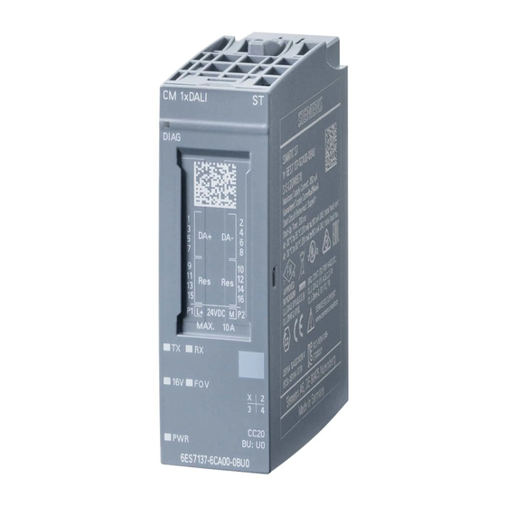
Product overview Properties Article number 6ES7137-6CA00-0BU0 View of the module ① ⑧ Module type and name LED for the supply voltage ② ⑨ LED for diagnostics Function class ③ ⑩ 2D matrix code Color coding module type ④ ⑪ Wiring diagram Function and firmware version ⑤... - Page 11 Product overview 2.1 Properties Properties The CM 1xDALI connects one DALI bus to the automation system and has the following properties: ● Technical properties: – DALI application controller (Multi-master) – 1xDALI bus with 4 pairs DALI+ and DALI- terminals (non-polarity) –...
- Page 12 Product overview 2.1 Properties ● Supported control gear types and input device types: – Fluorescent (control gear type 00) – Emergency lamp (control gear type 01) – Discharge lamp (control gear type 02) – Halogen (control gear type 03) – Incandescent (control gear type 04) –...
-
Page 13: Compatibility
Product overview 2.2 Compatibility Compatibility Connection to the system Through BaseUnit type U0, you can assemble a CM 1xDALI to the CPU, open controller, or IM of the ET 200SP distributed I/O system. Supported DALI devices You can only use the input device which meets the standard of DALI-2, IEC 62386-103. You can only use the control gear which meets the standard of DALI-1 or DALI-2. -
Page 14: Wiring
Wiring Important notes on using the device WARNING The equipment is designed for operation with Safety Extra-Low Voltage (SELV) or Protective Extra-Low Voltage (PELV). This means that electrical circuit in which the voltage cannot exceed 30 V AC (RMS), 42.4 V AC peak or 60 V DC under NORMAL CONDITIONS and CONDITIONS OF A SINGLE FAULT, including ground faults in other circuits. - Page 15 Wiring 3.1 Important notes on using the device General notices on use in hazardous areas according to FM WARNING Requirement for the installing enclosure If the equipment is installed within an ultimate enclosure, the inner service temperature of the enclosure corresponds to the ambient temperature of the module. WARNING Risk of burn injury If a device is operated in an ambient temperature of more than 50 °C, the temperature of...
-
Page 16: Installing Position
When installing and connecting up the CM 1xDALI, refer to the instructions in the system manual SIMATIC ET 200SP Distributed I/O system (https://support.industry.siemens.com/cs/ww/en/view/58649293) note the information in the document "Use of subassemblies/modules in a Zone 2 Hazardous Area" that you will find on the Internet at the following address: Link: (https://support.industry.siemens.com/cs/ww/en/view/78381013) -
Page 17: Dali Bus Cable
Wiring 3.3 DALI bus cable DALI bus cable Pay attention to the following requirements when you set up a DALI system. Requirement for DALI cable ● The voltage drop between the DALI power supply and any DALI device on the DALI bus must be less than 2 V. - Page 18 Wiring 3.3 DALI bus cable DALI bus topology CM 1xDALI is a gateway between automation system and DALI system. At the CPU side, CM 1xDALI works as a communication module and gateway to the system. At DALI side, CM 1xDALI works as an application controller. You can use line, tree, star or mixed structures to set up the DALI system.
-
Page 19: Block Diagram
ET 200SP distributed I/O system (https://support.industry.siemens.com/cs/ww/en/view/73021864). You can find information about selecting a suitable BaseUnit in the ET 200SP Distributed I/O System (https://support.industry.siemens.com/cs/ww/en/view/58649293) system manual and ET 200SP BaseUnits (https://support.industry.siemens.com/cs/ww/en/view/59753521) manual. You can find information on wiring the BaseUnit, connecting cable shields, etc. in the Connecting section of the ET 200SP Distributed I/O System (https://support.industry.siemens.com/cs/ww/en/view/58649293) system manual. - Page 20 Wiring 3.4 Block diagram Block diagram The following figure shows the block diagram and the terminal assignment of the CM 1xDALI. ① DALI+ connection Transmit LED (green) ② DALI- connection Receive LED (green) ③ Backplane bus interface Fault over voltage LED (red) ④...
- Page 21 Wiring 3.4 Block diagram L+/M supply voltage You connect the supply voltage (DC 24 V) to terminals L+ and M on a light BaseUnit. For a dark BaseUnit, it uses the supply voltage of the module on its left. An internal protection circuit protects the CM 1xDALI from reverse polarity of the supply voltage.
-
Page 22: Parameters
Parameters Parameter assignment Introduction You configure and assign the parameters of the communication module with STEP 7 V15.1 or later versions. In the CM 1xDALI project, you assign the parameters in the device view of STEP 7 and in the properties tab of the communication module DALI. CM 1xDALI Module Parameters Module Parameters Each CM 1xDALI has the following DALI parameters in Module Parameters. - Page 23 Parameters 4.2 CM 1xDALI Module Parameters Module Parameters Description Value range Default Configura- value tion in Diagnostics Diagnostics: Over Enable or disable the diagnostic message on DALI bus. Enable Enable • voltage on DALI bus Enable: When the DALI bus is connected to a fault •...
-
Page 24: Programming
(Page 32), Control gear dimming function blocks (Page 40), Diagnostic function blocks (Page 52) and Configuration function blocks (Page 67). Download the CM 1xDALI library from the Internet (https://support.industry.siemens.com/cs/ww/en/view/109767048). For more information about using libraries, refer to STEP 7 online help. CM 1xDALI data storage model CM 1xDALI data storage model A DALI device can be a control gear or input device. - Page 25 Programming 5.1 CM 1xDALI data storage model CM 1xDALI Database DALI device Database CPU sends data to CM 1xDALI, and CM 1xDALI stores the data. For example, the CPU uses DALI_ECG_SET_OPHOUR (Page 59) to set the operating hour of control gear in CM 1xDALI. CPU receives data from CM 1xDALI.
-
Page 26: General Information For Programming
Programming 5.2 General information for programming For the detailed parameter information on CM 1xDALI database and DALI device database, refer to the following table. Table 5- 1 Description for database parameters Parameters Storage location Read- Description only DALI 1xDALI devices DALI device ✓... -
Page 27: System Function Blocks
Programming 5.3 System function blocks About output parameter ● The outputs of the FBs are kept when the processing of job is done: – For the FBs with an input of CANCEL, only when both the trigger and input of CANCEL turn to zero, their output is reset. - Page 28 Programming 5.3 System function blocks ● The FB receives and reports the event messages which are sent be the DALI-2 input devices. ● When Bit 1 or Bit 2 of the CM_STATUS show "1", all the other DALI function blocks cannot be executed.
- Page 29 Programming 5.3 System function blocks Parameter Decla- Data Memory Description ration type area EVENT_S USInt I, Q, M, Event characterization that identifies the source of the event: CHEME D, L 0~4: Normal event message • 255: Power cycle event • Scheme of the event EVENT_S...
- Page 30 Programming 5.3 System function blocks Explanation of status Bit 8 Several error frames on the bus. Bit 9 to Bit 31 Reserved When the module is disabled by other DALI application controllers, the CM 1xDALI cannot send out any forward frame (16-bits or 24-bits) to the bus, but it can send out the response frame (8-bits) to other DALI application controllers.
-
Page 31: Dali_Send_Cmd
Programming 5.3 System function blocks Event information Event name description 2#00_0000_*01* Occupied The area is occupied. 2#00_0000_*11* Still occupied The area is still occupied. The event occurs at regular intervals as long as the occupied condition holds. 2#00_0000_0*** Presence sensor The current event is triggered by a presence based sensor. - Page 32 Programming 5.3 System function blocks Parameter The following table shows the parameters of the function block: Parameter Declaration Data type Memory Description area SEND Input BOOL I, Q, M, D, Send the DALI command upon a rising edge. L or Con- stant CMD_CO DWord...
-
Page 33: Addressing Function Blocks
Programming 5.4 Addressing function blocks Addressing function blocks Addressing function blocks are used for assigning short address, identifying devices, changing short address, or querying the address status of the DALI devices. 5.4.1 DALI_DEV_SCAN Description DALI_DEV_SCAN is used for scanning the DALI devices (control gears or input devices) on the bus through random address. - Page 34 Programming 5.4 Addressing function blocks Parameter The following table shows the parameters of the function block: Parameter Declaration Data type Memory Description area SCAN Input BOOL I, Q, M, D, Start the scan procedure upon a rising edge. L or Con- stant DEV_TYP USInt...
-
Page 35: Dali_Dev_Identify
Programming 5.4 Addressing function blocks 5.4.2 DALI_DEV_IDENTIFY Description DALI_DEV_IDENTIFY is used for identifying devices. If the control gear does not support the DALI command IDENTIFY, this function provides a light flicker method to identify the device by setting the level to maximum and minimum alternately. -
Page 36: Dali_Dev_Chg_Addr
Programming 5.4 Addressing function blocks Parameter Declaration Data type Memory Description area FLICKER BOOL I, Q, M, D, Specify the type of identification process: L or Con- FLICKER = 0: Identify the device by DALI command IDENTIFY. • stant The identifying process is specified by manufacturer. FLICKER = 1: Flicker the control gear to identify the device by •... - Page 37 Programming 5.4 Addressing function blocks Parameter The following table shows the parameters of the function block: Parameter Declaration Data type Memory Description area CHANGE Input BOOL I, Q, M, D, Change the short address of the specific device upon a rising edge. L or Con- stant DEV_TYP...
-
Page 38: Dali_Dev_Query_Addr
Programming 5.4 Addressing function blocks 5.4.4 DALI_DEV_QUERY_ADDR Description DALI_DEV_QUERY_ADDR is used for querying the address information of the DALI bus. ● When you set the input DET_ALL to 0, the FB queries the address information which is saved directly in the CM 1xDALI (refer to data flow path 2 (Page 23)). ●... - Page 39 Programming 5.4 Addressing function blocks Parameter The following table shows the parameters of the function block: Parameter Declaration Data type Memory Description area QUERY Input BOOL I, Q, M, D, Query the address information upon a rising edge. L or Con- stant DEV_TYPE USInt...
- Page 40 Programming 5.4 Addressing function blocks Parameter Declaration Data type Memory Description area ADDR_INFO AddrInfo- D, L Address information Detail UNADD BOOL UNADDR =1: At least one unaddressed device is detected on the DALI bus. EXCEED BOOL EXCEED =1: More than 64 control gears or input devices are scanned by using DALI_DEV_SCAN (Page 32).
-
Page 41: Control Gear Dimming Function Blocks
Programming 5.5 Control gear dimming function blocks Control gear dimming function blocks Control gear dimming function blocks are used for querying or setting the level and color of the control gears. 5.5.1 DALI_ECG_SWITCH Description DALI_ECG_SWITCH is used for switching on or off control gear, and you can also define the on and off level with this switch. - Page 42 Programming 5.5 Control gear dimming function blocks Parameter Declaration Data type Memory Description area ON_TYPE USint I, Q, M, D, Switch to the required level: L or Con- 0: Switch to the maximum level. • stant 1: Switch to the last active level. •...
-
Page 43: Dali_Ecg_Switch_Dim
Programming 5.5 Control gear dimming function blocks 5.5.2 DALI_ECG_SWITCH_DIM Description DALI_ECG_SWITCH_DIM is used for controlling the control gear (refer to data flow path 5 (Page 23)), and has the following features: ● If ON_UP sets to 1 and remains for the time which is shorter than the value of SHORT_PRESS, and then resets to 0, the control gear is switched on. - Page 44 Programming 5.5 Control gear dimming function blocks Parameter The following table shows the parameters of the function block: Parameter Declaration Data type Memory Description area ON_UP Input BOOL I, Q, M, D, Switch on or dim up upon a rising edge. L or Con- If ON_UP sets to 1 and remains for the time which is shorter than •...
- Page 45 Programming 5.5 Control gear dimming function blocks Parameter Declaration Data type Memory Description area ON_LEVEL USint I, Q, M, D, When ON_TYPE = 2, the value of ON_LEVEL is available. The con- L or Con- trol gear‘s target level sets to the required level when the switch is stant Range: 0 to 254 OFF_TYPE...
-
Page 46: Dali_Ecg_Query_Level
Programming 5.5 Control gear dimming function blocks 5.5.3 DALI_ECG_QUERY_LEVEL Description DALI_ECG_QUERY_LEVEL is used for querying the actual level of DALI control gears (refer to data flow path 6 (Page 23)). Parameter The following table shows the parameters of the function block: Parameter Declaration Data type... -
Page 47: Dali_Ecg_Set_Level
Programming 5.5 Control gear dimming function blocks 5.5.4 DALI_ECG_SET_LEVEL Description DALI_ECG_SET_LEVEL is used for setting the target level of DALI control gears (refer to data flow path 5 (Page 23)). Parameter The following table shows the parameters of the function block: Parameter Declaration Data type... -
Page 48: Dali_Ecg_Query_Color
Programming 5.5 Control gear dimming function blocks Parameter Declaration Data type Memory Description area BUSY Output BOOL I, Q, M, D, Status parameter: BUSY = 0: Processing of job is terminated. • BUSY = 1: Job is still being committed. •... - Page 49 Programming 5.5 Control gear dimming function blocks Parameter Declaration Data type Memory Description area ADDRESS USint I, Q, M, D, Specify the short address of the device. L or Con- Range: 0 to 63 stant CM_DALI InOut "DALI_CT The data block of DALI_CTRL specifies the CM 1xDALI which RL"...
-
Page 50: Dali_Ecg_Set_Color
Programming 5.5 Control gear dimming function blocks 5.5.6 DALI_ECG_SET_COLOR Description DALI_ECG_SET_COLOR is used for setting the actual color of DALI control gears that are compliant with IEC-62386-209, device type 8 (color control) (refer to data flow path 5 (Page 23)). If you use this FB to set color to a control gear which does not support color control, the command cannot take effect and does not report an error. -
Page 51: Dali_Ecg_Goto_Scene
Programming 5.5 Control gear dimming function blocks Parameter Declaration Data type Memory Description area TEMPER UInt The color value of temperature. ATURE (K) = 1000000 / "TEMPERATURE" Range: 1 to 65534 CM_DALI InOut "DALI_CT The data block of DALI_CTRL specifies the CM 1xDALI which RL"... - Page 52 Programming 5.5 Control gear dimming function blocks Parameter The following table shows the parameters of the function block: Parameter Declaration Data type Memory Description area GOTO Input BOOL I, Q, M, D, Go to the specified scene upon a rising edge. L or Con- stant GROUP...
-
Page 53: Diagnostic Function Blocks
Programming 5.6 Diagnostic function blocks Diagnostic function blocks Diagnostic function blocks are used for querying the status information of all the DALI devices. 5.6.1 DALI_DEV_GTIN Description DALI_DEV_GTIN is used for querying the GTIN (Global Trade Item Number) of device (refer to data flow path 6 (Page 23)). -
Page 54: Dali_Ecg_Status
Programming 5.6 Diagnostic function blocks Parameter Declaration Data type Memory Description area ERROR BOOL I, Q, M, D, Status parameter: ERROR = 0: No error occurs. • ERROR = 1: Error occurs during processing. • STATUS BYTE I, Q, M, D, When ERROR = 0, STATUS has When ERROR = 1, STATUS following three values:... - Page 55 Programming 5.6 Diagnostic function blocks Parameter Declaration Data type Memory Description area ACTIVE BOOL I, Q, M, D, Status parameter: ACTIVE = 0: Job is not yet started. • ACTIVE = 1: Job is being executed. • DONE BOOL I, Q, M, D, Status parameter: DONE = 0: Job is not yet started or still executing.
- Page 56 Programming 5.6 Diagnostic function blocks Parameter Declaration Data type Memory Description area EXT_ST BYTE Show the type-related failure status of the control gear which com- ATUS pliant with the IEC62386-20x. When 1 ≤ ACTUAL_TYPE ≤ 8, each Bit of EXT_STATUS indicates the different error types.
-
Page 57: Dali_Ecg_Status_Check
Programming 5.6 Diagnostic function blocks Parameter BASIC_STATUS Each Bit of the BASIC_STATUS indicates the different status: Status Explanation Bit 0 Control gear The control gear cannot be operated as intended. failure Bit 1 Lamp failure The lamp cannot operate as intended. Bit 2 Lamp on The lamp is on. - Page 58 Programming 5.6 Diagnostic function blocks Parameter The following table shows the parameters of the function block: Parameter Declaration Data type Memory Description area CHECK Input BOOL I, Q, M, D, Compare the specified status mask with the control gears upon a L or Con- rising edge.
-
Page 59: Dali_Ecg_Query_Ophour
Programming 5.6 Diagnostic function blocks 5.6.4 DALI_ECG_QUERY_OPHOUR Description DALI_ECG_QUERY_OPHOUR is used for querying the operation hour of DALI control gear. The operation hour accumulates when the control gear remains on for one hour. The operation hour is stored in the CM 1xDALI (refer to data flow path 2 (Page 23)). If you change short adresses of two control gears, the operating hours of these two control gears are not be changed, you exchange the related operation hours of these two control gears by using DALI_ECG_SET_OPHOUR (Page 59). -
Page 60: Dali_Ecg_Set_Ophour
Programming 5.6 Diagnostic function blocks Parameter Declaration Data type Memory Description area BUSY Output BOOL I, Q, M, D, Status parameter: BUSY = 0: Processing of job is terminated. • BUSY = 1: Job is still being committed. • ACTIVE BOOL I, Q, M, D, Status parameter:... -
Page 61: Dali_Sensor_Status
Programming 5.6 Diagnostic function blocks Parameter The following table shows the parameters of the function block: Parameter Declaration Data type Memory Description area Input BOOL I, Q, M, D, Set the operation hour upon a rising edge. L or Con- stant ADDRES USInt... - Page 62 Programming 5.6 Diagnostic function blocks Parameter The following table shows the parameters of the function block: Parameter Declaration Data type Memory Description area READ Input BOOL I, Q, M, D, Query the status of sensor upon a rising edge. L or Con- stant ADDRESS USInt...
- Page 63 Programming 5.6 Diagnostic function blocks Parameter Declaration Data type Memory Description area ADDR_S BYTE Show the control status of the device: TATUS 1: Normal status • 2: No device with the short address • 3: The DALI device displays an error frame. This error may be •...
-
Page 64: Dali_Sensor_Input
Programming 5.6 Diagnostic function blocks Parameter DEV_STATUS Each Bit of the DEV_STATUS indicates the different status: Status Explanation Bit 0 Input device error The input device or its instances has an error. Bit 1 Quiescent mode The input device does not produce any forward frame. Bit 2 Short address is No short address is assigned to this device. - Page 65 Programming 5.6 Diagnostic function blocks Parameter The following table shows the parameters of the function block: Parameter Declaration Data type Memory Description area READ Input BOOL I, Q, M, D, Query status of sensor upon a rising edge. L or Con- stant ADDRES USInt...
-
Page 66: Dali_Sensor_Status_Check
Programming 5.6 Diagnostic function blocks 5.6.8 DALI_SENSOR_STATUS_CHECK Description DALI_SENSOR_STATUS_CHECK is used for checking the status of input device (sensor). For the detailed status bits description, refer to DEV_STATUS in DALI_SENSOR_STATUS (Page 60). You can set the status mask of all the sensors, compare with the actual status that is stored in the CM 1xDALI, and then return the matching result. - Page 67 Programming 5.6 Diagnostic function blocks Parameter The following table shows the parameters of the function block: Parameter Declaration Data type Memory Description area CHECK Input BOOL I, Q, M, D, Compare the specified status mask with sensors upon a rising edge. L or Con- stant STATUS_...
-
Page 68: Configuration Function Blocks
Programming 5.7 Configuration function blocks Configuration function blocks Configuration function blocks are used for configuring the parameters of all the DALI devices. These function blocks allow to store configuration data in the CM 1xDALI module. The configuration in the modules database can be built up by uploading the physical devices or by configuring from the CPU. - Page 69 Programming 5.7 Configuration function blocks Parameter The following table shows the parameters of the function block: Parameter Declaration Data type Memory Description area Input BOOL I, Q, M, D, Add or modify one configured control gear upon a rising edge. L or Con- stant ADDRES...
-
Page 70: Dali_Ecg_Delete
Programming 5.7 Configuration function blocks 5.7.2 DALI_ECG_DELETE Description DALI_ECG_DELETE is used for deleting one configured control gear. This function block does not send any command to the DALI bus, but deletes the device which is added by using DALI_ECG_ADD (Page 67) and the data which is saved in the CM 1xDALI (refer to data flow path 1 (Page 23)). -
Page 71: Dali_Ecg_Query_Basic_Param
Programming 5.7 Configuration function blocks 5.7.3 DALI_ECG_QUERY_BASIC_PARAM Description DALI_ECG_QUERY_BASIC_PARAM is used for querying the basic parameters of DALI control gears. ● When you set the input "PHY_DEV" to 1, this function block queries the parameters from the physical device (refer to data flow path 6 (Page 23)). ●... - Page 72 Programming 5.7 Configuration function blocks Parameter Declaration Data type Memory Description area DONE BOOL I, Q, M, D, Status parameter: DONE = 0: Job is not yet started or still executing. • DONE = 1: Job is executed without errors. •...
-
Page 73: Dali_Ecg_Set_Basic_Param
Programming 5.7 Configuration function blocks Parameter Declaration Data type Memory Description area EXT_FA USInt Multiplier of the extend fade time DE_MUL Range: 0 to 5 EXT_FADE_MUL extemdedFadeTimeMultiplier 0 ms 100 ms 10 s 1 min In case FADE_TIME = 0, extended fade time is used, fade time = extendedFadeTimeBase * extemdedFadeTimeMultiplier Note: Extended fade time is only supported by devices compliant with DALI 2.0. - Page 74 Programming 5.7 Configuration function blocks Parameter The following table shows the parameters of the function block: Parameter Declaration Data type Memory Description area Input BOOL I, Q, M, D, Set basic parameters of the control gear upon a rising edge. L or Con- stant ADDRESS...
- Page 75 Programming 5.7 Configuration function blocks Parameter Declaration Data type Memory Description area 100 ms 10 s 1 min In case FADE_TIME = 0, extended fade time is used, fade time = extendedFadeTimeBase * extemdedFadeTimeMultiplier Note: Extended fade time is only supported by devices compliant with DALI-2.
-
Page 76: Dali_Ecg_Query_Ext_Param
Programming 5.7 Configuration function blocks 5.7.5 DALI_ECG_QUERY_EXT_PARAM Description DALI_ECG_QUERY_EXT_PARAM is used for querying the extended parameters of DALI control gears. ● When you set the input "PHY_DEV" to 1, this function block queries the extended parameters from the physical device (refer to data flow path 6 (Page 23)). ●... - Page 77 Programming 5.7 Configuration function blocks Parameter The following table shows the parameters of the function block: Parameter Declaration Data type Memory Description area QUERY Input BOOL I, Q, M, D, Query the extended parameters of the control gear upon a rising L or Con- edge.
- Page 78 Programming 5.7 Configuration function blocks Table 5- 2 The extended parameters of DALI control gears Attrib- BYTE Type 1 Type 2 Type 3 Type 4 Type 5 Type 6 Type 7 Type 8 utes (incan- (emer- (dis- (halo- (con- (LED) (switch) (color control) gency)
- Page 79 Programming 5.7 Configuration function blocks Attrib- BYTE Type 1 Type 2 Type 3 Type 4 Type 5 Type 6 Type 7 Type 8 utes (incan- (emer- (dis- (halo- (con- (LED) (switch) (color control) gency) charge) gen) verter) scent) Read Extend Extend Extend Extend...
-
Page 80: Dali_Ecg_Set_Ext_Param
Programming 5.7 Configuration function blocks 5.7.6 DALI_ECG_SET_EXT_PARAM Description DALI_ECG_SET_EXT_PARAM is used for setting the extended parameters of DALI control gears. The extended parameters are type-related. ● If the status of control gear is configured (for example, control gear is added by using DALI_ECG_ADD (Page 67)), the parameters are saved in the CM 1xDALI (refer to data flow path 1 (Page 23)) and sent to the physical device (refer to data flow path 5 (Page 23)). - Page 81 Programming 5.7 Configuration function blocks Parameter The following table shows the parameters of the function block: Parameter Declaration Data type Memory Description area Input BOOL I, Q, M, D, Set extended parameters of the control gear upon a rising edge. L or Con- stant ADDRES...
- Page 82 Programming 5.7 Configuration function blocks Table 5- 3 The extended parameters of DALI control gears Attributes BYTE Type 1 Type 4 Type 5 Type 6 Type 7 Type 8 (incan- (emer- (convert- (LED) (switch) (color control) descent) gency) Read/Writ Emer- Dimming Dimming Dimming...
-
Page 83: Dali_Ecg_Query_Group
Programming 5.7 Configuration function blocks 5.7.7 DALI_ECG_QUERY_GROUP Description DALI_ECG_QUERY_GROUP is used for querying the group membership of DALI control gears. ● When you set the input "PHY_DEV" to 1, this function block queries the group membership from the physical device (refer to data flow path 6 (Page 23)). ●... -
Page 84: Dali_Ecg_Set_Group
Programming 5.7 Configuration function blocks Parameter Declaration Data type Memory Description area STATUS BYTE I, Q, M, D, When ERROR = 0, STATUS has When ERROR = 1, STATUS following three values: shows the detailed error code. For the detailed meaning of each 16#00: Idle •... - Page 85 Programming 5.7 Configuration function blocks Parameter The following table shows the parameters of the function block: Parameter Declaration Data type Memory Description area Input BOOL I, Q, M, D, Set the group membership of the control gear upon a rising edge. L or Con- stant ADDRES...
-
Page 86: Dali_Ecg_Query_Scene
Programming 5.7 Configuration function blocks 5.7.9 DALI_ECG_QUERY_SCENE Description DALI_ECG_QUERY_SCENE is used for querying the scene configuration of the control gear. ● When you set the input "PHY_DEV" to 1, this function block queries the scene information from the physical device (refer to data flow path 6 (Page 23)). ●... - Page 87 Programming 5.7 Configuration function blocks Parameter Declaration Data type Memory Description area BUSY Output BOOL I, Q, M, D, Status parameter: BUSY = 0: Processing of job is terminated. • BUSY = 1: Job is still being committed. • ACTIVE BOOL I, Q, M, D, Status parameter:...
-
Page 88: Dali_Ecg_Set_Scene
Programming 5.7 Configuration function blocks 5.7.10 DALI_ECG_SET_SCENE Description DALI_ECG_SET_SCENE is used for setting the scene configuration of the control gear. ● You can set the scene level and scene color of one scene. ● If the control gear does not support the color control function, only scene level can be set. In this case, the input COLOR_TYPE under the "SCENE_INFO"... - Page 89 Programming 5.7 Configuration function blocks Parameter Declaration Data Memory Description type area COOR UInt The x-coordinate value of the point in the CIE color DINAT space chromaticity diagram. X-coordinate = "COORDINATE_X" * 1/65536. Range: 0 to 65534 COOR UInt The y-coordinate value of the point in the CIE color DINAT space chromaticity diagram.
-
Page 90: Dali_Sensor_Add
Programming 5.7 Configuration function blocks 5.7.11 DALI_SENSOR_ADD Description DALI_SENSOR_ADD is used for adding or modifying one configured sensor, including its instances. ● In order to add one configured sensor, you must set the sensor type of the instance. ● The total number of instances within all sensors which you can add is limited to 64. If the total number of instance exceeds the limitation, this function block returns an error of 16#87 (not supported). - Page 91 Programming 5.7 Configuration function blocks Parameter The following table shows the parameters of the function block: Parameter Declaration Data type Memory Description area Input BOOL I, Q, M, D, Add or modify one configured sensor upon a rising edge. L or Con- stant ADDRES USInt...
-
Page 92: Dali_Sensor_Delete
Programming 5.7 Configuration function blocks 5.7.12 DALI_SENSOR_DELETE Description DALI_SENSOR_DELETE is used for deleting one configured sensor, including its instances. This function block does not send any command to the DALI bus, but deletes the device which is added by using DALI_SENSOR_ADD (Page 89) and the data which is saved in the CM 1xDALI (refer to data flow path 1 (Page 23)). -
Page 93: Dali_Sensor_Query_Dev_Param
Programming 5.7 Configuration function blocks 5.7.13 DALI_SENSOR_QUERY_DEV_PARAM Description DALI_SENSOR_QUERY_DEV_PARAM is used for querying the device parameters of the input device (sensor). ● When you set the input "PHY_DEV" to 1, this function block queries the parameters from the physical device (refer to data flow path 6 (Page 23)). ●... -
Page 94: Dali_Sensor_Set_Dev_Param
Programming 5.7 Configuration function blocks Parameter Declaration Data type Memory Description area BUSY Output BOOL I, Q, M, D, Status parameter: BUSY = 0: Processing of job is terminated. • BUSY = 1: Job is still being committed. • ACTIVE BOOL I, Q, M, D, Status parameter:... - Page 95 Programming 5.7 Configuration function blocks Parameter The following table shows the parameters of the function block: Parameter Declaration Data type Memory Description area Input BOOL I, Q, M, D, Set device parameters of the sensor upon a rising edge. L or Con- stant ADDRES USInt...
-
Page 96: Dali_Sensor_Query_Inst_Param
Programming 5.7 Configuration function blocks 5.7.15 DALI_SENSOR_QUERY_INST_PARAM Description DALI_SENSOR_QUERY_INST_PARAM is used for querying the instance parameters of the input device (sensor). ● When you set the input "PHY_DEV" to 1, this function block queries the parameters from the physical device (refer to data flow path 6 (Page 23)). ●... - Page 97 Programming 5.7 Configuration function blocks Parameter Declaration Data type Memory Description area ACTIVE BOOL I, Q, M, D, Status parameter: ACTIVE = 0: Job is not yet started. • ACTIVE = 1: Job is being executed. • DONE BOOL I, Q, M, D, Status parameter: DONE = 0: Job is not yet started or still executing.
-
Page 98: Dali_Sensor_Set_Inst_Param
Programming 5.7 Configuration function blocks Table 5- 4 Sensor instance type-related parameters Attributes BYTE Type 1 (push button) Type 2 (absolute input) Type 3 (occupancy) Type 4 (light sensor) tShort Read/Write Deadtime Hold time Hysteresis tDouble Report time Report time Hysteresis min tRepeat Not used... - Page 99 Programming 5.7 Configuration function blocks Parameter The following table shows the parameters of the function block: Parameter Declaration Data type Memory Description area Input BOOL I, Q, M, D, Set the instance parameters of the sensor upon a rising edge. L or Con- stant ADDRESS...
- Page 100 Programming 5.7 Configuration function blocks Parameter Declaration Data type Memory Description area CM_DALI InOut "DALI_CT The data block of DALI_CTRL specifies the CM 1xDALI which RL" communicates with the current function block. BUSY BOOL I, Q, M, D, Status parameter: Output BUSY = 0: Processing of job is terminated.
-
Page 101: Dali_Dev_Upload
Programming 5.7 Configuration function blocks 5.7.17 DALI_DEV_UPLOAD Description DALI_DEV_UPLOAD is used for uploading all the parameters of the DALI device and saving them in the CM 1xDALI (refer to data flow path 4 (Page 23)). After this function block is executed without errors, the DALI device is marked as configured, and the setting parameters are saved in the CM 1xDALI. - Page 102 Programming 5.7 Configuration function blocks Parameter The following table shows the parameters of the function block: Parameter Declaration Data type Memory Description area UPLOAD Input BOOL I, Q, M, D, Upload parameters from the device upon a rising edge. L or Con- stant DEV_TYP USInt...
-
Page 103: Dali_Dev_Download
Programming 5.7 Configuration function blocks Table 5- 6 Description of STATUS on upload process Device type STATUS Comment Control 16#01 Querying basic parameters gear 16#02 Querying extended parameters 16#03 Querying group configuration 16#04 Querying scene configuration 16#05 Saving all parameters Input device 16#11 Querying sensor parameters and saving... - Page 104 Programming 5.7 Configuration function blocks Parameter The following table shows the parameters of the function block: Parameter Declaration Data type Memory Description area DOWNLO Input BOOL I, Q, M, D, Download parameters from the device upon a rising edge. L or Con- stant DEV_TYP USInt...
-
Page 105: Dali_Dev_Reset
Programming 5.7 Configuration function blocks Table 5- 7 Description of STATUS on download process Action PROC Comment Control 16#01 Querying status of the control gear Gear 16#02 Setting basic parameters 16#03 Setting type-related parameters 16#04 Setting group configuration 16#05 Setting scene configuration Input device 16#11 Querying status of the sensor... - Page 106 Programming 5.7 Configuration function blocks Parameter The following table shows the parameters of the function block: Parameter Declaration Data type Memory Description area RESET Input BOOL I, Q, M, D, Reset the parameters upon a rising edge. L or Con- stant DEL_ADD BOOL...
-
Page 107: Parameter Status
Programming 5.8 Parameter STATUS Parameter STATUS The following table shows the explanation of each STATUS value: ● When the value of STATUS is greater than 16#80: It shows the detailed error code. ● When the value of STATUS is less than 16#80: It indicates the progress of the function block. -
Page 108: Electric Control Gear (Ecg) Type
Programming 5.9 Electric control gear (ECG) type Electric control gear (ECG) type The following table shows the detailed device types of the control gears: Table 5- 9 Device type of the electric control gear Type ID Device type 16#00 Fluorescent 16#01 Emergency lamp 16#02... - Page 109 Programming 5.11 Description for EVENT_FILTER Description Value Long press start event enabled? "1" = "Yes" Long press repeat event enabled? "1" = "Yes" Long press stop event enabled? "1" = "Yes" Button stuck/free event enabled? “1” = “Yes” Absolute input device (type 2) Description Value Position event enabled?
-
Page 110: Diagnostic Alarms
Diagnostic alarms Status and error displays LED display ① ④ LED display DIAG LED display integrate DALI power 16 V ② ⑤ LED display TX LED display detected over voltage on DALI Bus (Threshold value: 45 V) ③ ⑥ LED display RX LED display PWR Figure 6-1 LED displays... - Page 111 Diagnostic alarms 6.1 Status and error displays Table 6- 2 Meaning of the TX/RX LED displays Meaning Solution Interface is transmitting Flashes Interface is receiving Flashes When the CM 1xDALI receives an "IDENTIFY DEVICE" command (IEC 62386-103), the LED Rx and Tx flash simultaneously at a frequency of 1 Hz and last about 10 seconds. Table 6- 3 Meaning of the 16V displays Meaning...
-
Page 112: Diagnostics Alarms
Diagnostic alarms 6.2 Diagnostics alarms Diagnostics alarms A diagnostics alarm is generated and the DIAG-LED flashes on the module for each diagnostics event. Read out the diagnostics alarms, for example, in the diagnostics buffer of the CPU. Evaluate the error codes with the user program. Diagnostic Error code Meaning... -
Page 113: Technical Specification
Technical specification Technical specifications Article number 6ES7137-6CA00-0BU0 General information Product type designation CM 1xDALI Firmware version FW update possible • usable BaseUnits BU type U0 Color code for module-specific color identifica- CC20 tion plate Product function Yes; I&M0 to I&M3 I&M data •... - Page 114 Technical specification 7.1 Technical specifications Article number 6ES7137-6CA00-0BU0 Diagnostic messages Yes; On DALI bus Short-circuit • Diagnostics indication LED ERROR LED • Yes; Green PWR LED Monitoring of the supply voltage (PWR- • LED) Yes; Green LED Receive RxD • Yes;...
-
Page 115: Appendix A Parameter Data Record
Appendix A Parameter data record Parameter assignment and structure of parameter data record You have the option of reassigning module parameters with the user program while the CPU is in RUN. The parameters are transferred to the module using data record 128, for example, with the WRREC instruction. - Page 116 Appendix A Parameter data record The following table shows the module-specific error codes and their meaning for the parameter data record 128: Table A- 2 Error message Error code Meaning 80B1 Error in data length 80E0 Error in header information 80E1 Parameter error ET 200SP Communication module CM 1xDALI (6ES7137-6CA00-0BU0)
-
Page 117: Appendix B Approvals
Appendix B Approvals This chapter lists the approval for ET 200SP CM 1xDALI specifically. Detailed references to the other approvals of CM 1xDALI are listed in the document 200SP Distributed I/O system. Note Information of the ET 200SP CM 1xDALI The currently valid markings and approvals are printed on the components of the ET 200SP CM 1xDALI. - Page 118 Test number: DEKRA 19ATEX0045 X You should also note the information in the document "Use of subassemblies/modules in a Zone 2 Hazardous Area" that you will find on the Internet at the following address: Link (https://support.industry.siemens.com/cs/ww/en/view/78381013): c(UL)us Applied standards: ● Underwriters Laboratories, Inc.: UL 61010-1 (Safety Requirements for Electrical...
- Page 119 Appendix B Approvals cULus Hazardous (Classified) Locations Underwriters Laboratories, Inc.: CULUS Listed E472610 IND. CONT. EQ. FOR HAZ. LOC. Applied standards: ● ANSI ISA 12.12.01 ● CSA C22.2 No. 213-M1987 APPROVED for Use in: ● Cl. 1, Div. 2, GP. A, B, C, D T4 ●...
-
Page 120: Glossary
Glossary Battery charge Show level of the battery charge. Color space Color space plane scaled in such a way that any color within it may be identified with two coordinates x and y, where x and y are both in the range 0 to 1. Color temperature Tc A black body (perfect radiant body) changes its color from red through yellow to white as its temperature increases (black body line –... - Page 121 Glossary Device group Type of address used to address a group of control devices in the system at once Dimming curve The dimming curve defines how dimmers set voltage output in response to control signal input, such as a slider position. You can set the dimming curve of the control gear as below: 0: sets the dimming curve to linear.
- Page 122 Glossary Error hold-off time The ERROR HOLD-OFF TIME specifies the minimum time an error must be continuously present in order to be indicated Total operation time. Event An instance report, characterized by its event number, of a change or a defined sequence of changes of its input value Fast fade time The Fast Fade Time is used instead of the Fade Time if the Fade Time is equal to 0.
- Page 123 Glossary Prolong time Time the extended emergency mode lasts after restoration of the mains supply Report time If the report timer is set, it shall generate a ‘repeat’ trigger every Treport even if the "inputValue" has not changed. The report timer shall be restarted every time an event is sent.
- Page 124 Glossary Up switch off threshold Value against which the virtual arc power level is continually compared, the output of the control gear being switched off whenever the virtual arc power level reaches or passes this level whilst increasing. Up switch on threshold Value against which the virtual arc power level is continually compared, the output of the control gear being switched on whenever the virtual arc power level reaches or passes this level whilst increasing.
-
Page 125: Index
Index Addressing function blocks, 32 Instance type of input devices, 107 Article number, 9 Module Parameters, 21 Background detection, 22 Basic parameter, 21 Diagnostics, 22 Period, 22 CM 1xDALI data storage model and data flow, 23 CM 1xDALI database, 25 CM 1xDALI library, 23 Program a DALI application, 25 Download the CM 1xDALI library, 23... - Page 126 Index ET 200SP Communication module CM 1xDALI (6ES7137-6CA00-0BU0) Manual, 06/2019, A5E46959434-AA...
Need help?
Do you have a question about the SIMATIC ET 200SP CM 1xDALI and is the answer not in the manual?
Questions and answers