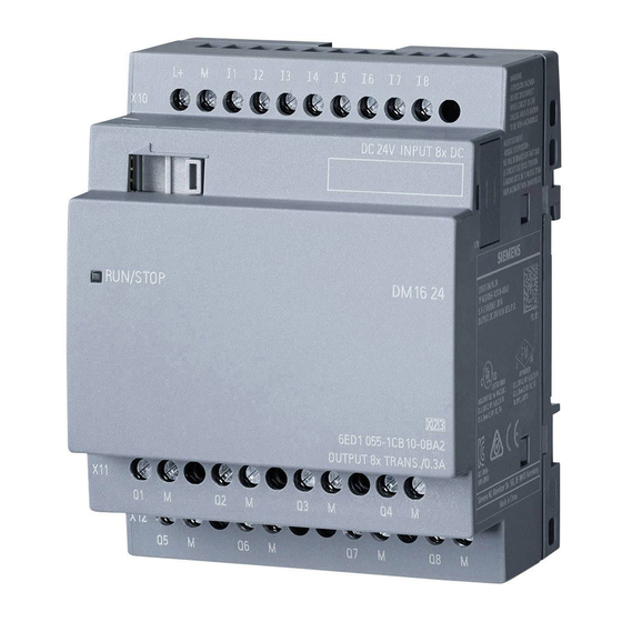
Siemens LOGO! Series Manual
Hide thumbs Also See for LOGO! Series:
Table of Contents

Advertisement

Welcome to LOGO!
Dear customer,
Thank you for purchasing LOGO!, and congratulations on your decision.
In LOGO! you have acquired a logic module that meets the stringent qual-
ity requirements of ISO 9001.
LOGO! is universal in application. Its comprehensive functionality and
great ease of use make it a highly cost-efficient solution for virtually any
application.
LOGO! documentation
This LOGO! manual tells you how to install, progam and use LOGO!.
In addition, the step-by-step graphical guide shipped with LOGO! and the
LOGO!Soft online help system provide you with the essentials.
LOGO!Soft is a programming package that runs on PCs under WindowsT .
It will help you get to know LOGO! and test, print and archive programs.
Guide to the manual
We have subdivided this manual into 6 chapters:
S
Getting to know LOGO!
S
Installing and wiring LOGO!
S
Programming LOGO!
S
Parameterizing LOGO!
S
Applications
S
Technical data
Additional support
If you have any questions concerning LOGO!, the dealer from whom you
bought it will be glad to help you.
Safety guidelines
This manual contains notices which you should observe to ensure your own personal
safety, as well as to protect the product and connected equipment. These notices are
highlighted in the manual by a warning triangle and are marked as follows according
to the level of danger:
LOGO! manual
EWA 4NEB 712 6006-02
i

Advertisement

Table of Contents
loading

Summary of Contents for Siemens LOGO! Series

  • Page 1 Welcome to LOGO! Dear customer, Thank you for purchasing LOGO!, and congratulations on your decision. In LOGO! you have acquired a logic module that meets the stringent qual- ity requirements of ISO 9001. LOGO! is universal in application. Its comprehensive functionality and great ease of use make it a highly cost-efficient solution for virtually any application.
  • Page 2 Copyright E Siemens AG 1996 All rights reserved The reproduction, transmission or use of this document or its contents is not permitted without express written authority. Offenders will be liable for damages. All rights, including rights created...
  • Page 3: Table Of Contents

    Contents Getting to know LOGO! ... Installing and wiring LOGO! ..Installing/deinstalling LOGO! ....Wiring LOGO! .
  • Page 4 Contents Blocks (BN) ........Memory required and size of a circuit .
  • Page 5 Contents Automatic door ....... . 5.2.1 Demands on an automatic door .
  • Page 6 Contents LOGO! manual EWA 4NEB 712 6006-02...
  • Page 7: Getting To Know Logo

    1 Getting to know LOGO! What is LOGO! ? – LOGO! is the new universal logic module from Siemens. With dimensions of 72 x 90 x 55 mm, LOGO! provides: Control functions An operating and display unit A power supply...
  • Page 8 Getting to know LOGO! Versions The following different versions of LOGO! are available: LOGO! 230 RC – Power supply and digital inputs: 115 V AC / 230 V AC – Digital outputs: relays, max. 8 A – 4 time switches (clocks) with up to 3 on and off times each LOGO 230R –...
  • Page 9: Installing And Wiring Logo

    2 Installing and wiring LOGO! You install LOGO! in a distribution box or cabinet, ensuring that the con- nectors are covered. If they are not, there is a danger of touching live parts. LOGO! must be installed and wired by a trained technician who knows and complies with both the universally applicable engineering rules and the regulations and standards that apply in specific cases.
  • Page 10: Installing/Deinstalling Logo

    Installing and wiring LOGO! 2.1 Installing/deinstalling LOGO! You install LOGO! on a DIN rail as follows: 1. Place LOGO! on the rail. 2. Swivel it. The snap catch on the back of LOGO! must engage. Depending on the type of DIN rail used, the snapping mechanism may be a bit stiff.
  • Page 11: Wiring Logo

    Installing and wiring LOGO! 2.2 Wiring LOGO! Use a screwdriver with a head 3 mm wide to wire LOGO!. You do not need wire end ferrules for the connectors. You can use wires up to the following sizes: 1 x 2.5 mm 2 x 1.5 mm 2.2.1 Connecting the power supply LOGO! 230R and LOGO! 230RC are suitable for line voltages with a rat-...
  • Page 12: Connecting Logo!'S Inputs

    Installing and wiring LOGO! 2.2.2 Connecting LOGO!’s inputs Requirements You connect sensors to the inputs. The sensors may be switches, photo- electric barriers or daylight control switches, for example. Sensor attributes for LOGO! 230R and LOGO! 230RC LOGO! recognizes the switch state 0 (switch open) at  40 V AC. The maximum input current is 0.24 mA (switches with glow lamps can cause problems if the closed-circuit current of the glow lamps is greater than 0.2 mA.
  • Page 13 Installing and wiring LOGO! Connecting You connect the sensors to LOGO! as follows: L+ L+ L+ L+ L+ L+ LOGO! 24/R LOGO! 230R/RC Warning Existing safety regulations (VDE 0110, ... IEC 1131, ... and UL and CSA) prohibit the connection of different phases to the in- puts of LOGO! 230R/RC.
  • Page 14: Connecting Outputs

    Installing and wiring LOGO! 2.2.3 Connecting outputs LOGO! 230R, LOGO! 230RC and LOGO! 24R The outputs of LOGO! 230R, LOGO! 230RC and LOGO! 24R are relays. The contacts of the relays are isolated from the power supply and the in- puts.
  • Page 15 Installing and wiring LOGO! LOGO! 24 The outputs of LOGO! 24 are switched by means of transistors. The out- puts are short circuit-proof and overload-proof. A separate voltage supply to the load is not necessary; LOGO! 24 supplies the load with voltage. Requirements for transistor outputs The load connected to LOGO! 24 must have the following properties: The maximum switched current is 0.3 amperes.
  • Page 16: Switching Logo! On/Resumption Of Power Supply

    Installing and wiring LOGO! 2.3 Switching LOGO! on/resumption of power supply LOGO! does not have a power switch. How LOGO! responds when switched on depends on: Whether a program is stored in LOGO! Whether a memory card is inserted The state LOGO! was in before power off The table indicates LOGO!’s responses to the possible situations: Then LOGO! does not contain a program...
  • Page 17 Installing and wiring LOGO! Try to remember the 4 simple rules for starting LOGO!: 1. If there is no program in LOGO! or on the memory card, LOGO! dis- plays the message: No Program 2. If there is a program on the memory card, it is copied to LOGO! auto- matically.
  • Page 18: Programming Logo

    3 Programming LOGO! By programming, we mean entering a circuit. A LOGO! program is really no more than a circuit diagram represented in a different way. We have changed the way it is represented to suit LOGO!’s display panel. What does this chapter contain? It begins by telling you something about how a circuit is stored in LOGO!.
  • Page 19: Circuit Diagram

    Programming LOGO! 3.1 Circuit diagram You know, of course, how a circuit is represented in a circuit diagram. Here is an example: The consumer E1 is switched on and off by means of the switches S1 OR S2. The relay K1 picks up when S1 or S2 is closed.
  • Page 20: Connectors And Blocks

    Programming LOGO! 3.2 Connectors and blocks We would like to begin by showing you how we denote the connectors and blocks and by describing the function of the blocks. We will then show you how to enter a circuit in LOGO!. Here is a brief overview of what awaits you: Connectors and blocks Connectors...
  • Page 21: Connectors

    Programming LOGO! 3.3 Connectors LOGO! has inputs and outputs: Inputs SIEMENS Outputs Each input is identified by the letter I with a number. When you look at LOGO! from the front, you see the connectors for the inputs at the top right.
  • Page 22 Programming LOGO! The inputs and outputs can have the state ’0’ or ’1’. ’0’ means there is no voltage at the input, and ’1’ means that there is. But that is unlikely to be new to you. We introduced the connectors hi, lo and x in order to facilitate program entry for you.
  • Page 23: Basic Functions

    Programming LOGO! 3.4 Basic functions When you enter a circuit, you will find the blocks for basic functions in the GF list. The following basic functions exist: Circuit diagram Representation in Basic function representation LOGO! Series connection of normally open contacts Parallel connection of normally open...
  • Page 24: And

    Programming LOGO! 3.4.1 AND The series connection of a number of The symbol for AND is as follows normally open contacts is represented in a circuit diagram as follows: The block is called AND because its output (Q) has the state 1 only when I1 and I2 and I3 have the state 1 (i.e.
  • Page 25: Not

    Programming LOGO! Logic table for OR: The following applies to OR: x = 0 (x means the input is not used) 3.4.3 NOT An inverter is represented in a In LOGO! the inverter is called circuit diagram as follows: NOT: The symbol for this is as follows: The block is called NOT because the output (Q) has the state 1 when the input has the state 0, and vice versa.
  • Page 26: Nand

    Programming LOGO! 3.4.4 NAND The parallel connection of a num- In LOGO! this is a NAND block. ber of normally closed contacts is The symbol for it is as follows: represented in a circuit diagram as follows: The block is called NAND because its output (Q) only has the state 0 if I1 and I2 and I3 have the state 1 (i.e.
  • Page 27: Xor

    Programming LOGO! The block is called NOR because its output (Q) only has the state 1 when all the inputs have the state 0. As soon as any of the inputs takes on the state 1, the output of NOR has the state 0. Logic table for NOR The following applies to NOR: x = 0 (x means the input is not used)
  • Page 28: Special Functions

    Programming LOGO! 3.5 Special functions When you enter a program in LOGO!, you will find the special functions in the SF list. The following special functions exist: Circuit diagram Representation in Special function representation LOGO! On-delay Off-delay Pulse relay Clock pulse generator Latching relay Clock pulse generator LOGO! manual...
  • Page 29: Accuracy Of The Time

    Programming LOGO! Circuit diagram Representation in Special function representation LOGO! Retentive on-delay Counter up and down Note In all functions, R has priority over all other inputs. Note After a power failure/power restoration, in the case of time functions the time that has elapsed is reset, and in the case of the counter the counted value is reset.
  • Page 30: On-Delay

    Programming LOGO! 3.5.2 On-delay The on-delay is represented in a In LOGO! the symbol for on- circuit diagram by a relay with on- delay is as follows: delay: Trg input You start the time for the on-delay by means of the Trg input (TRG stands for trigger) Parameter T T is the time after which the output...
  • Page 31: Off-Delay

    Programming LOGO! 3.5.3 Off-delay The off-delay is represented in a cir- In LOGO! the symbol for the off- cuit diagram by a relay with off- delay is as follows: delay: Trg input You start the time for the off-delay by means of the Trg input (Trg stands for trigger) R input You reset the time for the off-delay and set the output to 0...
  • Page 32: Pulse Relay

    Programming LOGO! 3.5.4 Pulse relay The pulse relay in a circuit Symbol for the pulse relay in diagram: LOGO! Trg input You use the Trg input (Trg stands for trigger) to switch the output on and off. R input You use the R input (reset) to reset the pulse relay and set the output to 0 (R has priority over Trg) Timing diagram...
  • Page 33: Clock (Time Switch)

    Programming LOGO! 3.5.5 Clock (time switch) A time switch is only available in LOGO! versions that have the letter C (for clock) in their name (e.g. LOGO! 230 RC). Each clock has 3 cams. The block for the clock is as follows: No 1 No 2 No 3...
  • Page 34 Programming LOGO! Switch-on time Any time between 00:00 and 23:59 hours ––:–– means there is no switch-on time Switch-off time Any time between 00:00 and 23:59 hours ––:–– means there is no switch-off time Clock buffer In LOGO! 230RC, the internal clock continues to run when there is a power failure.
  • Page 35: Setting The Clock (Time Switch)

    Programming LOGO! 3.5.6 Setting the clock (time switch) To enter switching times, proceed as follows: 1. Position the cursor on one of the clock’s No parameters (e.g. No1). 2. Press the OK key. LOGO! opens the parameter window for the cam. The cursor is positioned on the day of the week.
  • Page 36 Programming LOGO! Example 2 The clock’s output is to be switched on every day from 08:00 hours to 13:00 hours and from 15:00 hours to 18:30 hours. You need 2 cams for this: B01:No1 B01:No2 Day= Mo..Su Day= Mo..Su On =08:00 On =15:00 Off=13:00 Off=18:30...
  • Page 37: Latching Relay

    Programming LOGO! 3.5.8 Latching relay Very often, a circuit is required that retains a switched-on state. This is referred to as latching. Latching is represented in a circuit diagram as fol- lows: LOGO! has a separate block for this type of cir- cuit.
  • Page 38: Clock Pulse Generator

    Programming LOGO! 3.5.9 Clock pulse generator A clock pulse generator in a cir- The symbol for a clock pulse gen- cuit diagram: erator in LOGO! En input You switch the clock pulse generator on and off via the En in- put (enable).
  • Page 39: Retentive On-Delay

    Programming LOGO! 3.5.10 Retentive on-delay Retentive on-delay in a cir- Retentive on-delay in LOGO! cuit diagram: Trg input You start the time for the on-delay via the Trg (trigger) input R input You reset the time for the on-delay and set the output to 0 via the R (reset) input(R has priority over Trg) T parameter T is the time after which the output is switched on (the output...
  • Page 40: Up And Down Counter

    Programming LOGO! 3.5.11 Up and down counter The symbol for the up/down counter is as follows: R input You reset the internal count value and the output to zero via the R (reset) input (R has priority over Cnt). Cnt input The counter counts the changes from state 0 to state 1 at the Cnt (count) input.
  • Page 41 Programming LOGO! At each positive edge at the Cnt input, the internal counter is incremented by one (Dir = 0) or decremented by one (Dir = 1). If the internal count value is greater than or equal to the value specified for Par, the output (Q) is set to 1.
  • Page 42: Blocks (Bn)

    Programming LOGO! 3.6 Blocks (BN) Whenever you insert a block in a program, LOGO! gives this block a num- ber, the block number. The block number appears at the top right of the display. LOGO! uses the block numbers to indicate the connections between blocks: Block number The block number...
  • Page 43: Memory Required And Size Of A Circuit

    Programming LOGO! 3.7 Memory required and size of a circuit A program (or circuit diagram, if you prefer) is subject to limitations with regard to: The number of blocks connected in series The memory available Number of blocks connected in series You can insert a series of up to 7 blocks between an input and an output.
  • Page 44 Programming LOGO! The following table gives you an overview of how much memory each function block occupies in each memory area: Memory area Function Basic functions On-delay Off-delay Pulse relay Clock (time switch) Latching relay Clock pulse generator Retentive on-delay Counter Memory limits in LOGO! Example:...
  • Page 45 Programming LOGO! The sample program contains: Block Memory area Function B01 OR B02 AND B03 Clock B04 On-delay B05 Clock pulse generator B06 AND Memory occupied by the program Memory limits in LOGO! Still available in LOGO! A program contains: Thus, the program fits in LOGO!.
  • Page 46: The Golden Rules For Working With Logo

    Programming LOGO! 3.8 The golden rules for working with LOGO! Rule 1 You enter the circuit in programming mode. You switch to programming mode by pressing the 3 keys , and OK simultaneously. You change the values of times and parameters in parameterization mode. You switch to parameterization mode by pressing the 2 keys ESC and OK simultaneously.
  • Page 47: Overview Of Logo!'S Menus

    Programming LOGO! 3.9 Overview of LOGO!’s menus Programming mode Main menu Programming menu >Program.. >Edit Prg PC/Card.. Clear Prg Start Set Clock PC/card menue >PC´LOGO LOGO³Card Card³LOGO Parameterization mode Parameterization menu >Set Clock Set Param LOGO! manual EWA 4NEB 712 6006-02...
  • Page 48: Converting A Circuit Diagram To A Block Representation

    Programming LOGO! 3.10Converting a circuit diagram to a block representation You create a circuit in LOGO! by connecting blocks and connectors to each other. Consider the following circuit: Wiring: You connect the switches to LOGO!’s inputs: S1 S2 S3 I1 I2 I3 You convert the circuit to blocks.
  • Page 49: Entering A Program

    Programming LOGO! 3.11 Entering a program You have designed a circuit and now want to enter it in LOGO!. The ex- ample below illustrates how to do this. 3.11.1 Switching to programming mode You have connected LOGO! to the mains and switched on the power. The following message appears on the display: No Program Switch LOGO! to programming mode.
  • Page 50: First Program

    Programming LOGO! >Edit Prg LOGO!’s programming menu Clear Prg Set Clock Here too, you can move the ”>” by pressing the keys. Position the ”>” on ”Edit Prg” (i.e. to enter the program), and press the OK key. LOGO! then shows you the first output: LOGO!’s first output You can use the keys to select the other outputs.
  • Page 51: Editing The Program

    Programming LOGO! The wiring is as follows: SIEMENS Switch S1 acts on input I2, and switch S2 acts on input I2. The consumer is connected to relay Q1. 3.11.3 Editing the program Let’s enter the program now (from the output to the input). Initially, LOGO! displays the output: LOGO!’s first output...
  • Page 52 Programming LOGO! The cursor indicates your position in the program. At this point, enter only the first block (the OR block). Press the OK key to switch to input mode. The cursor appears in the form of a solid block: You can select a connector or block.
  • Page 53 Programming LOGO! The following appears in the display panel Your program looks like this Block number You have now entered the first block. Every block you enter receives a number, the block number. All you have to do now is wire the inputs of the block.
  • Page 54 Programming LOGO! The following appears in Your program looks like this the display panel – Now connect input I2 to the input of the OR block. You know how to do this already: 1. Switch to input mode: 2. Select the Co list: 3.
  • Page 55 Programming LOGO! The following appears in the Your program looks like this display panel If you want to have another look at your first program, you can use the key or the cursor to move through the program. But we are going to exit program input now and switch LOGO! to RUN. To do this, proceed as follows: 1.
  • Page 56 Programming LOGO! LOGO! represents the state of an input or output as follows: I:123456 Input/output has the state ’1’: inverse Mo 09:00 Input/output has the state ’0’: not inverse Q:1234 RUN Let’s have a look at that in our example: When switch S1 is closed, volt- age is applied to input I1, which has the state ’1’.
  • Page 57: Second Program

    Programming LOGO! 3.11.4 Second program We use the second program to show you: How to insert a block in an existing program How to select a block for a special function How to enter parameters In order to produce the second program, we modify the first one. Let’s begin by looking at the circuit diagram for the second program: You know the first part of the cir- cuit already.
  • Page 58 Programming LOGO! Inserting an additional block in a program Move the cursor to the B of B01 (B01 is the block number of the OR block). Move the cursor: Press At this point we insert the new block. Press the OK button: LOGO! displays the BN list.
  • Page 59 Programming LOGO! Select the desired block (off-delay, see next diagram), and press the OK key: The inserted block receives the block num- ber B02. Block B01, which has been con- nected up to now to Q1, is connected auto- matically to the uppermost input of the in- serted block.
  • Page 60 Programming LOGO! LOGO! displays the parameter window for parameters: B02: the parameter of block B02 B02:T is a time T=00.00s+ The parameter is displayed in parame- terization mode and can be modified there Time value Time unit The cursor appears on the first position of the time value. To change the time value, proceed as follows: Use the keys to move the cursor to the different positions.
  • Page 61: Deleting A Block

    Programming LOGO! This branch of the program for Q1 is now complete. LOGO! displays the Q1 output. You can have another look at the program on the display. Use the keys to move through the program. Use to move from block to block, and use to move between the inputs on a block.
  • Page 62: Deleting A Number Of Interconnected Blocks

    Programming LOGO! 2. Press the OK key. 3. Connect block B01 instead of block B02 directly to output Q01: Select the BN list, and then press OK. Select B01, and then press OK. Result: Block B02 is deleted. Block B01 is now connected directly to the output instead of block B01.
  • Page 63: Correcting Typing Errors

    Programming LOGO! 3.11.7 Correcting typing errors It is easy to correct typing errors in LOGO!: If you have not yet concluded input, you can use ESC to go back a step If you have already concluded input, simply start again: 1.
  • Page 64 Programming LOGO! >Program.. PC/Card.. Start 2. Move the ’>’ to ’Program..’ using the key, and press OK LOGO! switches to the pro- >Edit Prg gramming menu: Clear Prg Set Clock 3. Move the ’>’ to ’Clear Prg’: 4. Accept ’Clear Prg’: To prevent you from inadvertently Clear Prg deleting your program, we have...
  • Page 65: Using The Program Module/Card

    Programming LOGO! 3.12Using the program module/card You can copy the program stored in LOGO! to a program module/card. You can then insert the program module/card in a different LOGO! and copy the program to it. You can use the program module/card to: Archive programs Duplicate programs Send programs by post...
  • Page 66: Removing The Program Module/Card

    Programming LOGO! 3.12.1 Removing the program module/card You can change the program module/card when the power is on and LOGO! is in RUN or the programming mode. However, please heed the following warning: Warning Only use LOGO! 230 with the cover or the program module/ card inserted.
  • Page 67: Copying A Program From Logo! To The Program Module/Card

    Programming LOGO! Carefully insert a screwdriver into the slot at the upper end of the program module/card, and ease the program module/card out of the shaft a little. You can now remove the program module/card. Inserting the program module/card The shaft for the program module/card is chamfered at the bottom on the right.
  • Page 68: Copying A Program From The Program Module/Card

    Programming LOGO! LOGO! copies the program to the program module/card. While it is doing this, a ’#’ flashes on the display: PC´LOGO >LOGO³Card Card³LOGO Flashes When LOGO! has finished copying, it returns to the main menu: Program.. >PC/Card.. Start The program is now also on the program module/card. You can remove the program module/card.
  • Page 69 Programming LOGO! Result: LOGO! copies the program from the program module/card to LOGO!. While LOGO! is copying, a ’#’ flashes on the display. As soon as LOGO! has finished copying, LOGO! displays the main menu: >Program.. PC/Card.. Start Now you can switch LOGO! to RUN: Note Before you switch LOGO! to RUN, you must ensure that the system you are controlling with LOGO! does not represent a source of danger.
  • Page 70 Programming LOGO! 4. Press OK. The transfer menu appears: PC´LOGO LOGO³Card >Card³LOGO 5. Move the ’>’ to ’Card ³ LOGO’: 6. Press OK. LOGO! copies the program from the progam module/card to LOGO!. When LOGO! has finished copying, it returns to the main menu: LOGO! manual EWA 4NEB 712 6006-02...
  • Page 71: Connecting Logo! To A Pc

    Programming LOGO! 3.13Connecting LOGO! to a PC To connect LOGO! to a PC, you need the LOGO! PC cable. Remove the cover or the program module/card, and connect the cable there. Switch LOGO! to PC´LOGO mode So that the PC can access LOGO!, LOGO! must be in PC ´ LOGO mode. To switch LOGO! to PC ´...
  • Page 72: Parameterizing Logo

    4 Parameterizing LOGO! By parameterization we mean setting the parameters of blocks. You can set delay times for time functions, switching times for clocks (time switches) and the threshold value of a counter. You can set the parameters: In programming mode In parameterization mode In parameterization mode, the programmer sets a value for a parameter.
  • Page 73: Switching To Parameterization Mode

    Parameterizing LOGO! 4.1 Switching to parameterization mode To switch to parameterization mode, press ESC and OK simultaneously: I:123456 Mo 09:00 Q:1234 RUN LOGO! switches to parameterization mode and displays the parameteriza- tion menu: >Set Clock Set Param The ’Set Clock’ menu item is displayed only if your version of LOGO! has a clock/time switch (those versions of LOGO! that have a clock have the letter C in their name, e.g.
  • Page 74: Parameters

    Parameterizing LOGO! 4.1.1 Parameters Parameters can be: The delay times of a time relay The switching times (cams) of a clock The threshold value of a counter How do you recognize a parameter? Simple: by its block number. Every parameter is identified by the block number and the parameter abbrevi- ation.
  • Page 75: Changing A Parameter

    Parameterizing LOGO! If no parameter can be set, LOGO! displays the following: No parameter can be changed: No Param ESC returns you to the parametrization menu Press ESC 3. Select the desired parameter: LOGO! displays a parameter in a separate window. 4.
  • Page 76 Parameterizing LOGO! Current value of a time T If you view a time T in parameterization mode, it looks like this: B01:T T = 12:00m Time T set = 00:00m Current time T You can change the set time T (see ”Changing a parameter”). Current value of the clock If you view a cam of a clock in parameterization mode, it looks like this, for example:...
  • Page 77: Setting The Time (Logo! 230 Rc)

    Parameterizing LOGO! 4.2 Setting the time (LOGO! 230 RC) You can set the time: In parameterization mode In programming mode Setting the time in parameterization mode: 1. Switch to parameterization mode: ESC and OK simultaneously 2. Select ’Set Clock’, and press OK Set Clock The cursor is positioned before the day of the week...
  • Page 78: Applications

    5 Applications To give you a feeling for the kind of situations in which you can use LOGO!, we have compiled a number of application examples. We have in- cluded the circuit diagram of the original solution for each example. For the solutions using LOGO!, we have included the wiring and a diagram.
  • Page 79: Stairway, Hall Or Corridor Lighting

    Applications 5.1 Stairway, hall or corridor lighting 5.1.1 Demands on stairway lighting The lighting system of a stairway should fulfill the following requirements: The light should be on when someone is on the stairway. If there is nobody on the stairway, the light should be off to save energy. 5.1.2 Previous solution Previously there were 2 ways of switching the lighting: By means of an impulse relay...
  • Page 80: Lighting System With Logo

    Applications Lighting system with a pulse relay When a pulse relay is used, the lighting system behaves as follows: When any switch is pressed: The lighting is switched on When any switch is pressed again: The lighting is switched off. Disadvantage: People often forget to switch the light off again.
  • Page 81 Ï Ï Ï Ï Ï Ï Lights L1 N I1 I2 I3 I4 I5 I6 SIEMENS Switches LOGO! 230RC The external wiring of the lighting system with LOGO! is the same as for a conventional hall, corridor or stairway lighting system. The difference is that the automatic lighting device or the pulse relay is replaced.
  • Page 82 Applications Multi-functional switch with LOGO! Off-delay Switch light on On-delay Switch light off 06:00m 02.00s Switch permanent light on Latching relay Pulse-relay The diagram shows the circuit for an input with an associated output. This switch offers the following: When the switch is pressed: The light is switched on and goes off again after the set time of 6 minutes (T=06:00m) has elapsed (off-delay) When the switch is pressed twice: The light is switched on perma- nently (the latching relay is set via the impulse relay).
  • Page 83: Special Features And Enhancement Options

    Applications 5.1.4 Special features and enhancement options Features such as the following are available for adding functions or saving energy: You can have the light flash before it goes off automatically. You can integrate various central functions: – Central off –...
  • Page 84: Automatic Door

    Applications 5.2 Automatic door You often find automatic door control systems at the entrances to supermar- kets, public buildings, banks, hospitals, etc. 5.2.1 Demands on an automatic door When somebody approaches, the door must open automatically. The door must remain open until there is nobody in the doorway any more.
  • Page 85: Previous Solution

    Applications 5.2.2 Previous solution Auxiliary circuit Open Close Open door Waiting time As soon as one of the motion detectors B1 or B2 registers somebody’s pres- ence, the door is opened by K3. If the two motion detectors detect nothing for a minimum period, K4 en- ables the close operation.
  • Page 86 Applications Wiring of the door control system with LOGO! 230RC L1 N I1 I2 I3 I4 I5 I6 SIEMENS LOGO! 230RC Open Close Components used Master contactor Open Master contactor Close Limit switch Closed Limit switch Open Infrared motion detector Outside...
  • Page 87 Applications Diagram of the door control system with LOGO! 230RC & Open & & Close This is what the functional block diagram that corresponds to the circuit diagram of the conventional solution looks like. You can simplify this circuit if you make use of LOGO!’s functions. You can use the off-delay to replace the latching relay and on-delay.
  • Page 88: Special Features And Enhancement Options

    (so that it only opens during shop opening hours and only from the in- side to the outside after closing time, for example). 5.2.5 Enhanced LOGO! 230 RC solution Wiring of the enhanced LOGO! solution O-A-C L1 N I1 I2 I3 I4 I5 I6 SIEMENS LOGO! 230RC Open Close Buzzer LOGO! manual...
  • Page 89 Applications Functional block diagram of the enhanced LOGO! solution No1: Detecting motion Day= Mo..Fr On = 09:00 Off =18:00 No2: Day= Sa On = 08:00 Off =13:00 Motion detector B1 No1: T= 10 s Day= Mo..Fr On = 09:00 Off =19:00 No2: Day= Sa On = 08:00...
  • Page 90 Applications After closing time, motion detector B2 continues to open the door for 1 hour so that customers can leave the shop. Motor for opening Output Q1 is switched on and opens the door when the control switch at I5 is operated (the door is to be constantly open), or the motion detectors indicate that somebody is approaching the door, and the door is not yet completely open (limit switch at I4).
  • Page 91: Ventilation System

    Applications 5.3 V entilation system 5.3.1 Demands on a ventilation system A ventilation system is used either to feed fresh air into a room or to remove used air from it. Consider the following example: É É É É É É É É É É É É É É É É É É É É É É...
  • Page 92 LOGO! module. Wiring of the ventilation system with LOGO! 230RC S3 v> v> L1 N I1 I2 I3 I4 I5 I6 SIEMENS LOGO! 230RC Exhaust ventilator Fresh air ventilator Components used Master contactor...
  • Page 93: Advantages Of Using Logo

    Applications Block diagram of the LOGO! solution The block diagram of the ventilation control system with LOGO! is as fol- lows: Fault Exhaust ventilator Exhaust ventilator Fresh air Exhaust air ventilator Exhaust air ventilator flow monitor Exhaust air flow monitor 10 s Exhaust air ventilator Q2 Fresh air flow...
  • Page 94 Applications Functional diagram of the enhanced LOGO! solution The ventilators at Q1 and Q2 are switched off as shown in the following circuit: Fault Exhaust ventilator 30 s Exhaust air flow monitor Fresh air ventilator Exhaust air ventilator 10 s Exhaust air flow monitor 10 s...
  • Page 95: Industrial Gate

    Applications 5.4 Industrial gate Warning Ô Ô Ô Ô light Safety pressure bar Ô Ô Ô Ô Ô Ô Ô Ô Ô Ô Ô Ô Ô Ô Ô Ô Ô Ô Ô Ô Ô Ô Ô Ô Ô Ô Ô Ô There is often a gate at the entrance to a company’s premises.
  • Page 96: Previous Solution

    Warning light Open Close Wiring of the gate control system with LOGO! 230RC p > Open Closed Stop L1 N I1 I2 I3 I4 I5 I6 SIEMENS LOGO! 230RC S5 p > Open Close Warning light LOGO! manual EWA 4NEB 712 6006-02...
  • Page 97 Applications Components used Master contactor Master contactor Stop switch Open switch Close switch Open position switch Closed position switch Safety pressure bar Functional diagram of the LOGO! solution Open start switch Open Stop switch Gate is open Flashing light Close start switch Close Stop switch...
  • Page 98: Enhanced Logo! Solution

    Applications 5.4.3 Enhanced LOGO! solution In our enhanced solution, the gate will automatically open again when the safety bar operates. Safety bar Gate is closed Open Stop switch Gate is open Open start switch Flashing light Close start switch Close Stop switch Safety bar Gate is closed...
  • Page 99: Fluorescent Lamps

    Applications 5.5 Fluorescent lamps É É É É É É É É É É É É É É É É É Fluorescent lamp 1 Fluorescent lamp 2 É É É É É É É É É É É É É É É É...
  • Page 100: Previous Solution

    Applications 5.5.2 Previous solution lx> The lights are operated by means of a pulse relay controlled by the switches at the door. Independently of this, they are reset by the time switch (clock) or by the brightness-sensitive switch via the central off input. The switch- ing-off commands must be cut by impulse relays so that it is still possible to switch the lights on and off locally after they have been switched off cen- trally.
  • Page 101: Fluorescent Lamp Control With Logo! 230Rc

    Applications 5.5.3 Fluorescent lamp control with LOGO! 230RC lx< L1 N I1 I2 I3 I4 I5 I6 SIEMENS LOGO! 230RC Fluorescent Fluorescent Fluorescent Fluorescent lamp 1 lamp 2 lamp 3 lamp 4 Components used S1 to S4 Switches Daylight control switch...
  • Page 102 Applications Functional diagram of the LOGO! solution Switch-off pulse generated by time switch (clock) Mo..Su 20:00 – 20.01 Mo..Su Lamp 3 21:00 – 21.01 Corridor side Lamp 4 Switch-off pulse generated by daylight control switch Corridor side Daylight control switch Lamp 1 Window side Lamp 2...
  • Page 103: Rainwater Pump

    Applications 5.6 Rainwater pump Rainwater is being used increasingly in homes in addition to drinking water. This saves money and is environment-friendly. You can use rainwater, for example, for: Washing clothes Watering the garden Watering house plants Washing the car Flushing the toilet The following drawing illustrates how a system for using rainwater works: Rainwater...
  • Page 104: Demands On The Control System For A Rainwater Pump

    Applications 5.6.1 Demands on the control system for a rainwater pump The water must be available at all times. Whenever necessary, the con- troller must switch automatically to drinking water. When the switch to drinking water takes place, no rainwater must get into the drinking water system.
  • Page 105: Rainwater Pump With Logo! 230Rc

    Applications 5.6.3 Rainwater pump with LOGO! 230RC p< L1 N I1 I2 I3 I4 I5 I6 SIEMENS LOGO! 230RC Pump Drinking water supply Apart from LOGO!, you need only the pressure switch and the float switches to control the pump. If you are using a three-phase motor, you need a master contactor.
  • Page 106: Special Features And Enhancement Options

    Applications Functional diagram of the LOGO! solution Pressure switch Pump T = 20 s Float switch for run-dry protection on Float switch for run-dry protection off Drinking water supply Float switch for drinking water supply on Float switch for drinking water supply off 5.6.4 Special features and enhancement options In the functional diagram you can see how to wire the control system for the...
  • Page 107: Dereeler

    Applications 5.7 Dereeler A metal strip (coil) is fed to a punching device over a dereeler. 5.7.1 Demands on a dereeler The following demands are placed on a dereeler: The metal strip must not sag. The metal fed to the punching device must not exceed a defined maxi- mum tension.
  • Page 108: Dereeler With Logo! 24R

    If you use LOGO!, you can make the circuit much simpler. You only have to connect the switches, the indicator light and the main contactor to LOGO!. Wiring the dereeler with LOGO! 24R L+ M I1 I2 I3 I4 I5 I6 SIEMENS LOGO! Enable punching device Dereeler...
  • Page 109: Advantages Of The Logo! Solution

    Applications Functional diagram of the LOGO! solution The block diagram for controlling the dereeler with LOGO! is as follows: Manual mode on Manual dereeler control Dereeler drive on Automatic mode on Punching device off Strip taut Strip loose Automatic mode on Punching device off Indicator light for automatic mode...
  • Page 110: Additional Application Options

    So drop us a line – no matter how un- usual or simple your LOGO! circuit is! We will be delighted to receive all your suggestions. Write to: Siemens AG AUT V16 – LOGO! Gleiwitzer Straße 555 D-90327 Nuremberg...
  • Page 111: Technical Data

    6 Technical data General technical data Criterion Complies with Values Dimensions W×H×D 72 x 90 x 55 in mm with installation mechanism: 72 x 90 x 59 Weight approx. 190 g Installation on 35 mm DIN rail Width of 4 modules Ambient climatic conditions Ambient temperature Cold: IEC 68-2-1...
  • Page 112 Technical data Criterion Complies with Values Electromagnetic compatibility (EMC) Electrostatic IEC 801-2 8 kV air discharge discharge Severity 3 6 kV contact discharge Electromagnetic fields IEC 801-3 Field strength 10V / m Interference suppression EN 55011 Limit class B group 1 Burst pulses IEC 801-4 2 kV...
  • Page 113 Relay outputs Electrical isolation In groups of Continuous current I Maximum 8 A Relay type V23961-A1007-A302 (Siemens) Incandescent lamp load 1000W (at 230/240 V AC) (25,000 switching cycles) 500W (at 115/120 V AC) 10 × 58W (at 230/240 V AC) Fluorescent tubes with electr.
  • Page 114 Technical data Short circuit-proof Power protection B16 cos 0.5 to 0.7 900A Parallel switching of outputs to Not permitted increase power Protection of output relay Maximum 16 A, Characteristic B16 Switching rate Mechanical 10 Hz ohm load/lamp load 2 Hz Inductive load 0.5 Hz Technical data of LOGO! 24...
  • Page 115 Technical data Digital outputs Output type Transistor, current-sourcing Electrical isolation In groups of ¢ Supply voltage Output voltage Output current Maximum 0.3 A Parallel switching of outputs to increase power Not permissible Short circuit-proof and overload-proof Short circuit current limiting Approx.
  • Page 116 Relay outputs Electrical isolation In groups of Continuous current Ith Maximum 8 A Relay type V23061-A1007-A302 (Siemens) Incandescent lamp load (25,000 switching 1000 W cycles) Fluorescent tubes with electr. control gear 10 x 58 W (25,000 switching cycles) Fluorescent tubes, conventionally compensated...
  • Page 117 Technical data Switching capacity and service life of the relay outputs Switching cycles / million DC 24V / max. 8 A AC 115/120 V / max. 8 A AC 230/240 V / max. 8 A Switched current / A Figure 1 Switching capacity and service life of the contacts at ohm load (heating) Switching cycles / million DC 24V / max.
  • Page 118: Abbreviations

    Abbreviations Block number B01 Block number Count (input for counter) Connector Direction (for counter: up or down) Enable (switching on the clock pulse generator) Grundfunktion (basic function) Nocke (cam for clock) Parameter for counter Reset Set (setting the latching relay) Special function Time (parameter) Current value of a time (the current value of a time is displayed in...

This manual is also suitable for:

Logo! 230 rcLogo 230rLogo! 24rLogo! 24

Table of Contents