
Related Manuals for Enterasys 7100G Series


Summary of Contents for Enterasys 7100G Series
- Page 1 Enterasys 7100G-Series ® 7100G-Series Switch Hardware Installation Guide 71G21K2L2-48P 71G21K2L2-24P24 71G11K2L2-48 P/N 9034795...
- Page 3 Enterasys Networks reserves the right to make changes in specifications and other information contained in this document and its web site without prior notice. The reader should in all cases consult Enterasys Networks to determine whether any such changes have been made.
- Page 4 Regulatory Compliance Information Federal Communications Commission (FCC) Notice This device complies with Part 15 of the FCC rules. Operation is subject to the following two conditions: (1) this device may not cause harmful interference, and (2) this device must accept any interference received, including interference that may cause undesired operation.
- Page 5 It is the users’ responsibility to utilize the available collection system to ensure WEEE is properly treated. For information about the available collection system, please contact Enterasys Customer Support at +353 61 705500 (Ireland). Battery Notice This product contains a battery used to maintain product information.
- Page 6 SJ/T 11363-2006 standard. This table shows where these substances may be found in the supply chain of Enterasys’ electronic information products, as of the date of sale of the enclosed product. Note that some of the component types listed above may or may not be a part of the enclosed product.
- Page 7 Safety Information Class 1 Laser Transceivers The single mode interface modules use Class 1 laser transceivers. Read the following safety information before installing or operating these modules. The Class 1 laser transceivers use an optical feedback loop to maintain Class 1 operation limits. This control loop eliminates the need for maintenance checks or adjustments.
- Page 8 2006/95/EC Manufacturer’s Name: Enterasys Networks, Inc. Manufacturer’s Address: 9 Northeastern Boulevard Salem, NH 03079 European Representative Name: Enterasys Networks Limited European Representative Address: Nexus House, Newbury Business Park London Road, Newbury Berkshire RG14 2PZ, England Conformance to Directive(s)/Product Standards: EC Directive 2004/108/EC...
- Page 9 CAREFULLY READ THIS LICENSE AGREEMENT. This document is an agreement (“Agreement”) between the end user (“You”) and Enterasys Networks, Inc., on behalf of itself and its Affiliates (as hereinafter defined) (“Enterasys”) that sets forth Your rights and obligations with respect to the Enterasys software program/firmware (including any accompanying documentation, hardware or media) (“Program”) in the package...
- Page 10 Agreement. 12. WAIVER. A waiver by Enterasys of a breach of any of the terms and conditions of this Agreement must be in writing and will not be construed as a waiver of any subsequent breach of such term or condition. Enterasys’ failure to enforce a term upon Your breach of such term shall not be construed as a waiver of Your breach or prevent enforcement on any other occasion.
- Page 11 14. TERMINATION. Enterasys may terminate this Agreement immediately upon Your breach of any of the terms and conditions of this Agreement. Upon any such termination, You shall immediately cease all use of the Program and shall return...
-
Page 13: Table Of Contents
Contents About This Guide Who Should Use This Guide ..........................xv How to Use This Guide .............................xv Related Documents ............................xvi Typographical Conventions ..........................xvi Getting Help ..............................xvii Chapter 1: Introduction 71G21K2L2-48P ............................. 1-1 71G21K2L2-24P24 ............................1-2 71G11K2L2-48 ............................... 1-2 AC Power Supplies ............................ - Page 14 Port LEDs ..............................3-1 System LEDs ............................3-4 Power Supply LED ........................... 3-5 Troubleshooting Checklist ..........................3-6 Replacing the 7100G-Series Fan Module ...................... 3-8 Removing a Power Supply ..........................3-9 Using the OFFLINE/RESET Button ......................3-10 Recommended Shutdown Procedure Using OFFLINE/RESET Button ..........3-10 Last Resort Shutdown Procedure Using OFFLINE/RESET Button ............
- Page 15 Power Conditioning ..........................E-1 Airflow Concerns for Closed Racks ......................E-2 Airflow Concerns for Open Racks ......................E-3 Dust Mitigation and Prevention ........................E-5 Airborne Chemicals and Prevention .......................E-6 Figures 71G21K2L2-48P I/O Port Panel ......................1-1 71G21K2L2-24P24 I/O Port Panel ..................... 1-2 71G11K2L2-48 I/O Port Panel......................1-2 7100G-Series Switch Rack Configurations ..................
- Page 16 Troubleshooting Checklist ........................3-6 7100-Series Switch Ports ........................A-1 Specifications .............................A-2 COM Port Pin Assignments ........................A-2 Compliance Standards ........................A-3 Contents of 71A-RACK-U ........................C-2 Powered Device Classifications ......................D-1 PoE LED Status..........................D-2 Airborne Dust Specification for Enterasys Equipment — Airborne Dust Maximum Values....E-6...
-
Page 17: About This Guide
A brief summary of each chapter • Definitions of the conventions used in this document • Instructions regarding how to obtain technical support from Enterasys Networks. To locate information about various subjects in this guide, refer to the following table. For... Refer to... -
Page 18: Related Documents
Related Documents The Enterasys 7100-Series Configuration Guide and Enterasys 7100-Series CLI Reference Guide provide information on how to use the CLI to set up and manage the 7100G-Series switch. The Enterasys 7100-Series Quick Reference provides an overview of key considerations when installing the 7100G-Series switch. -
Page 19: Getting Help
A description of any action(s) already taken to resolve the problem (for example, changing mode switches or rebooting the unit) • The serial and revision numbers of all involved Enterasys Networks products in the network • A description of your network environment (such as layout, cable type, other relevant environmental information) •... - Page 20 Getting Help xviii About This Guide...
-
Page 21: 71G21K2L2-48P
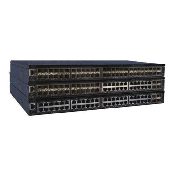
Introduction ® This chapter provides an overview of the capabilities of the Enterasys 7100G-Series models: • 71G21K2L2-48P • 71G21K2L2-24P24 • 71G11K2L2-48 For information about firmware features of the 7100G-Series switch and how to configure them, refer to the Enterasys 7100-Series Configuration Guide. -
Page 22: 71G21K2L2-24P24
The SFP+ and QSFP+ ports support a number of pluggable transceivers. For more information about the transceivers, see the following: http://www.enterasys.com/products/transceivers-ds.pdf 71G11K2L2-48 The 71G11K2L2-48 has forty-eight 100Mb/1Gb SFP ports, two 1/10Gb SFP+ ports and two 10/40Gb QSFP+ ports, as shown in Figure 1-3. -
Page 23: Ac Power Supplies
Management You can manage the 7100G-Series switch either in-band or out-of-band. In-band remote ® management is possible using the Enterasys Networks’ NetSight management application or the command line interface (CLI) via Telnet. Out-of-band management is provided through the RJ45 COM (Communication) port on the front panel using a PC, a VT terminal, or a VT terminal emulator. -
Page 24: Virtual Switch Bonding
(a virtual switch bonded chassis) managed by one IP address. Connect the chassis to each other by using the two 40Gb ports on each 7100G-Series chassis. Note: For virtual switch bonding configuration details, see the Enterasys 7100-Series Configuration Guide. -
Page 25: Required Tools
Read the Release Notes specific to the firmware image running in the chassis to check for any exceptions to the supported features and operation documented in this guide. Required Tools • ESD wrist strap (included with the 7100G-Series switch) • Phillips screwdriver Enterasys 7100G-Series Hardware Installation Guide 2-1... -
Page 26: Installation Site Requirements
7100G-Series Quick Reference Inspect the 7100G-Series switch for any signs of physical damage. If there are any signs of damage, DO NOT install the 7100G-Series switch; instead, contact Enterasys Networks. Refer to “Getting Help” on page xvii for details. 2-2 Installation... -
Page 27: Mounting The 7100G-Series Switch
Flush mounted with the switch I/O ports facing 3 Mid-mounted with the switch I/O ports facing front front (cool air side) Mid-mounting with the power supply facing front Flush mounted with the power supply facing Air flow direction front (cool air side) Enterasys 7100G-Series Hardware Installation Guide 2-3... -
Page 28: Power Supply Air Flow And Switch Fan Module Air Flow
Mounting the 7100G-Series Switch Power Supply Air Flow and Switch Fan Module Air Flow The power supply module has its own fan for cooling the power supply, and the switch fan module has four fans for cooling the switch circuitry. The air flow direction of both the power supply and fan modules must agree in order to properly cool the installed 7100G-Series system. -
Page 29: Reversing The Fan Module Air Flow
2-5. Slide the fan module forward until it is unplugged from the device. Figure 2-2 Removing the Switch Fan Module Fan module captive screws Fan module connector Switch Fan module Fan unit metal plate Enterasys 7100G-Series Hardware Installation Guide 2-5... -
Page 30: Reversing The Fan Unit
Mounting the 7100G-Series Switch Reversing the Fan Unit The switch fan module has a single reversible dual fan unit. When the fan unit is properly seated, the air flow indicator arrow is completely visible as shown in callout 1, Figure 2-3 on page 2-6. -
Page 31: Rack Mount Ear Positioning
I/O port side of the device. Reinsert the front screw, shown by callout 4, and retighten the middle screw, shown by callout Repeat steps 1–3 on the other side of the chassis. Enterasys 7100G-Series Hardware Installation Guide 2-7... -
Page 32: Mid-Mount Switch I/O Ports Facing Front Configuration
Mounting the 7100G-Series Switch Figure 2-4 Flush Mount Switch I/O Ports Front Configuration Ear mount screw removal Ear mount screw insertion Rack mount ear pivot screw Pivot screw retightened Reposition of rack mount ear Mid-Mount Switch I/O Ports Facing Front Configuration The mid-mount, switch I/O ports facing front configuration is depicted in callout 3 of Figure 2-1 on page 2-3. -
Page 33: Mid-Mount Power Supply Facing Front Configuration
2 and the thick black arrow. The three-holed ear is now located in the middle of the device, still facing the power supply side. Reinsert the two rack mount ear screws, shown by callout 3. Repeat steps 1–3 on the other side of the chassis. Enterasys 7100G-Series Hardware Installation Guide 2-9... -
Page 34: Securing The 7100G-Series Switch To The Rack
Mounting the 7100G-Series Switch Figure 2-6 Mid-Mount Power Supply Front Configuration Ear mount screw removal Ear mount screw insertion Reposition of rack mount ear Securing the 7100G-Series Switch to the Rack Warning: Before rack-mounting the device, ensure that the rack can support it without compromising stability. -
Page 35: Securing The 7100G-Series Switch To The Rack In A Flush Mount Configuration
Securing the 7100G-Series Switch to the Rack in a Flush Mount Configuration 4 or 6 screws or fasteners appropriate to the rack Figure 2-8 Securing the 7100G-Series Switch to the Rack in a Mid-Mount Configuration 4 - 6 screws or fasteners appropriate to the rack Enterasys 7100G-Series Hardware Installation Guide 2-11... -
Page 36: Flat Surface Installation
2-4. Remove the power supply from its protective plastic bag. Examine the power supply carefully, checking for damage. If there are any signs of damage, DO NOT install the power supply; instead, contact Enterasys Networks. Refer to “Getting Help” on page xvii for details. -
Page 37: Installing A Power Supply
7100G-Series switch and rotating the coverplate out of its position from right to left before disengaging it from the chassis (see Figure 2-10 on page 2-14). Reinstall the screw once the cover plate is removed. Enterasys 7100G-Series Hardware Installation Guide 2-13... -
Page 38: Powering Up The 7100G-Series Switch
Powering Up the 7100G-Series Switch Figure 2-10 Removing the Power Supply Bay Coverplate Coverplate Coverplate Screw Keep the coverplate in the event you need to revert to a single power supply configuration. If a power supply is not installed, the coverplate must be in place for proper air flow. Repeat steps 2–3 to install the power supply in the right power supply bay. -
Page 39: Connecting To The Network
Link Aggregation to operate properly. Before connecting the cables, refer to the Enterasys 7100-Series Configuration Guide for configuration information. For details on how to obtain manuals, refer to “Related Documents”... -
Page 40: Connecting Pluggable Transceivers To The Sfp+ And Qsfp+ Ports
QSFP+ to four SFP+ cable conversion. See the set port speed command information Enterasys 7100-Series CLI Reference for port configuration details. The two 10Gb ports are taken off-line when 40Gb ports are used in 4x10Gb mode. -
Page 41: 7100G-Series Switch Ground Receptacle
Refer to the instructions in the anti-static wrist strap package. See Figure 2-12 for the location of the ground receptacle. Figure 2-12 7100G-Series Switch Ground Receptacle Ground receptacle Enterasys 7100G-Series Hardware Installation Guide 2-17... -
Page 42: Multiple 7100G-Series Chassis Stacking (Virtual Switch Bonding)
Multiple 7100G-Series Chassis Stacking (Virtual Switch Bonding) Remove the pluggable transceiver from the packaging. If there is a protective dust cover on the pluggable transceiver, do not remove it at this time. Installing the Pluggable Transceiver To install an SFP+ or QSFP+ pluggable transceiver in the 7100G-Series switch: Hold the pluggable transceiver so that the connector will seat properly. -
Page 43: Connecting To The Com Port For Local Management
Plug the RJ45 connector at the other end of the cable into the RJ45-to-DB25 female adapter. Connect the RJ45-to-DB25 adapter to the port labeled COMM on the VT terminal. Turn on the VT terminal and access the Setup Directory. Set the following parameters: Enterasys 7100G-Series Hardware Installation Guide 2-19... -
Page 44: Adapter Wiring And Signal Assignments
Connecting to the COM Port for Local Management Pin Out Descriptions Parameter Setting Mode 7 Bit Control Transmit Transmit = 57600 Bits Parity 8 Bits, No Parity Stop Bit 1 Stop Bit When these parameters are set, the Local Management password screen will display. Refer to “Completing the Installation”... -
Page 45: Completing The Installation
Enterasys 7100 Series Configuration Guide. The CLI commands enable you to initially set up and perform more involved management configurations. The Enterasys 7100 Series Configuration Guide is available online at: https://extranet.enterasys.com/downloads/Pages/default.aspx Enterasys 7100G-Series Hardware Installation Guide 2-21... - Page 46 Completing the Installation Pin Out Descriptions 2-22 Installation...
-
Page 47: Chapter 3: Troubleshooting
Table 3-3 on page 3-3 for LED state definitions. • The PoE status for PoE capable (10/100/1000 PoE (.at+ .af capable) RJ45 ports. See “PoE Port Status LEDs” on page D-2 for PoE LED details. Enterasys 7100G-Series Hardware Installation Guide 3-1... -
Page 48: Sfp+ And Qsfp+ Port Leds
None Port enabled, but no activity. If you know the port should (Transmit) be active and is not, contact Enterasys Technical Support. Green (blinking) Indicates data transmission activity. None. Flashing frequency indicates the data rate. -
Page 49: Qsfp+ Port Leds
Amber Green Link present, port enabled, traffic is being None. (blinking/solid) (blinking) received by the interface. Amber (solid) A transmit fault or error condition exists Contact Enterasys Technical Support if assistance is required. Enterasys 7100G-Series Hardware Installation Guide 3-3... -
Page 50: System Leds
Power off. Ensure chassis has adequate power. Amber Blinking. Device in bootup process. None. Solid. Testing. If the LED remains amber for several minutes, contact Enterasys Networks for technical support. Green Blinking. Image starts running. None. Solid. Functional. None. Solid. Processor in reset. -
Page 51: Power Supply Led
Blinking. Bonding is not functional (non-operational). Power Supply LED The 71A-PS-A/B power supplies have a single LED and 71A-POE-A/B power supplies have two LEDs. Table 3-6 describes the different states of the power supply LEDs. Enterasys 7100G-Series Hardware Installation Guide 3-5... -
Page 52: Troubleshooting Checklist
7100G-Series to assign an IP address. switch through in- Port is disabled. Enable port. See the Enterasys 7100-Series Configuration Guide band management. for instructions to enable/disable ports. Host Port policy and/or management Verify that a management VLAN exists and that it is associated VLAN is incorrectly configured, or with the Host Port. - Page 53 Problem Possible Cause Recommended Action Port(s) goes into Loop condition detected. Verify that Spanning Tree is enabled. Refer to the Enterasys standby for no 7100-Series Configuration Guide for the instructions to set the apparent reason. type of STP. Review the network design and delete loops.
-
Page 54: Replacing The 7100G-Series Fan Module
Replacing the 7100G-Series Fan Module Replacing the 7100G-Series Fan Module The 7100G-Series switch is cooled by a fan module accessible from the power supply side of the unit. If the FAN LED and the output of the CLI show system command indicate that the fan module has failed, you must replace the failed fan module. -
Page 55: Removing A Power Supply
Precaución: Si desea trabajar sólo con una fuente de poder, no olvide colocar la tapa en el compartimiento de la fuente de poder que haya eliminado, para reducir la interferencia electromagnética y para asegurar una buena ventilación. Figure 3-5 Removing the Power Supply Enterasys 7100G-Series Hardware Installation Guide 3-9... -
Page 56: Using The Offline/Reset Button
Using the OFFLINE/RESET Button Lock Tab Power Supply Handle Using the OFFLINE/RESET Button You can shut down a 7100G-Series switch using the OFFLINE/RESET button, shown in Figure 3-6, which is slightly recessed behind the 7100G-Series switch faceplate. There are two procedures to shut down a 7100G-Series switch: •... -
Page 57: Last Resort Shutdown Procedure Using Offline/Reset Button
Recurra a él sólo como último recurso, puesto que interrumpe todos los procesos del módulo en funcionamiento, lo que podría resultar pérdidas de frames. To reset an 7100G-Series switch without it performing an orderly shutdown routine, press and hold the OFFLINE/RESET button for approximately 6 seconds. Enterasys 7100G-Series Hardware Installation Guide 3-11... - Page 58 Using the OFFLINE/RESET Button 3-12 Troubleshooting...
-
Page 59: 7100G-Series Switch Specifications
7100G-Series Switch Specifications Pluggable Transceiver Specifications COM Port Pinout Assignments Regulatory Compliance Enterasys Networks reserves the right to change specifications at any time without notice. 7100G-Series Switch Specifications Table A-1 describes I/O ports for the 7100G-Series switch. Table A-1 7100-Series Switch Ports... -
Page 60: Pluggable Transceiver Specifications
1.72” H x 17.61” W x 17.086” D Approximate Weight Gross: 7.12 kg (15.7 lb) Mean Time Between Failure (MTBF) Refer to the MTBF web site at URL http://www.enterasys.com/support/mtbf/ 71A-POE-A or 71A-POE-B Input Frequency 50 to 60 Hz Input (Voltage/Current) at Output Power... -
Page 61: Regulatory Compliance
(Class A), EN 55024, EN 61000-3-2, EN 61000-3-3, AS/NZ CISPR-22 (Class A). VCCI V-3. CNS 13438 (BSMI), 2004/108/EC (EMC Directive) Environmental 2011/65/EU (RoHS Directive), 2002/96/EC (WEEE Directive), Ministry of Information Order #39 (China RoHS) Enterasys 7100G-Series Hardware Installation Guide A-3... - Page 62 Regulatory Compliance A-4 Specifications...
-
Page 63: Appendix B: Clearing The Persistent Storage Or System Password
To either clear the 7100G-Series switch persistent storage or only the system password, proceed as follows: With the console port connected, power up the device. The following message displays: Boot ROM Initialization, Version 01.00.02 Copyright (c) 2012 Enterasys Networks, Inc. SDRAM size: 1024 MB Testing SDRAM..PASSED. -
Page 64: Clearing System Storage Or Password Using The Dip Switch Method
Enter admin at the username prompt. Enter a carriage-return at the password prompt. See the Image Configuration and File Management chapter of the Enterasys 7100 Series Configuration Guide for instructions on restoring a config if you cleared the NVRAM. Clearing System Storage or Password Using the Dip Switch Method Electrical Hazard: Only qualified personnel should perform installation procedures. -
Page 65: Required Tools
1 through 8 from left to right. Switch definitions and positions are as follows: • Switches 1– 6: For Enterasys Networks use only. • Switch 7: Clear Persistent Data. Changing the position of this switch from the up position to the down position clears persistent data on the next power-up of the 7100G-Series switch. -
Page 66: Setting The Mode Switches
Clearing System Storage or Password Using the Dip Switch Method Figure B-1 Mode Switch Location Fan Module Bay Mode Switches Setting the Mode Switches Before setting the mode switches, you must power down the 7100G-Series switch. Put on the ESD wrist strap and attach it to the ground receptacle on the switch I/O ports side of the 7100G-Series switch. -
Page 67: Required Tools
Removing the Rack Mount Ears from the 7100G-Series Chassis Installing the Adapter Plates 4-Post Rack Mount Installation 2-Post Rack Mount Installation Required Tools • ESD wrist strap (included with the 7100G-Series chassis) • Phillips screwdriver Enterasys 7100G-Series Hardware Installation Guide C-1... -
Page 68: Contents Of Mounting Kit
Contents of Mounting Kit Contents of Mounting Kit Table C-1 lists the contents of the 71A-RACK-U mounting kit. Table C-1 Contents of 71A-RACK-U Item Number Left and right rails and extensions assemblies Adapter plates Mid-Brackets 6-32 flat head screws 10-32 pan head screws (black) 10-32 cage nuts Note: The 71A-RACK-U mounting kit does not include rack screws. -
Page 69: Required Order Of Installation
The rail and mid-bracket assemblies used in the 2-post rack configuration (see “Pre- Installation Tasks” on page C-8) • The adapter plates can be installed in either a flush or a recessed configuration of up to 1.5 inch. Enterasys 7100G-Series Hardware Installation Guide C-3... -
Page 70: Installing The Adapter Plates
Installing the Adapter Plates Note: The side air vents are intentionally covered by the adapter plates in certain mounting configurations. The 7100G-Series switch cooling design is from front to back, not side to side. The 7100G-Series chassis can be configured for air intake on either the chassis switch I /O port side or the power supply side. -
Page 71: 4-Post Rack Mount Installation
The length of each assembly is adjustable from 22 inches to 30 inches. Each assembly is labeled either “right front” or “left front”. The front of the rack is always the cool air intake side. The rear of the rack is always the hot air exhaust side. Enterasys 7100G-Series Hardware Installation Guide C-5... -
Page 72: Rack Mount Rail With Attached Extension Assembly Installation
4-Post Rack Mount Installation Rack Mount Rail with Attached Extension Assembly Installation Refer to Figure C-4 on page C-6 as you perform the following procedure. To install the rack mount rail with extension assembly: Adjust the length of the two assemblies (callout 1) to agree with the distance between the outer face of the vertical rack posts. -
Page 73: 2-Post Rack Mount Installation
C-8 displays the 2-post rack flush mount and mid-mount configurations for supported air flow directions for a 3 inch post installation. The same configurations apply to a 7.25 inch post installation. The recessed chassis configurations are not displayed. Enterasys 7100G-Series Hardware Installation Guide C-7... -
Page 74: Pre-Installation Tasks
2-Post Rack Mount Installation Figure C-6 Two Post Rack Supported Configurations Flush mount, switch I/O port side to power supply side air flow Cool air intake side Flush mount, power supply side to switch I/O port side air flow Hot air exhaust side Mid-mount, switch I/O port side to power supply side air flow Air flow direction Mid-mount, power supply to switch I/O port side air flow... -
Page 75: Mid-Bracket To Rail Assembly
The 2-post rack mount rail can be installed in both a flush mount or mid-mount configuration. In a flush mount configuration, the rack mount rail is secured to both the front and rear flange of either a 3 inch or 7.25 inch rack post. Enterasys 7100G-Series Hardware Installation Guide C-9... -
Page 76: Securing Mid-Bracket To Rail 3 Inch Flush Mount
2-Post Rack Mount Installation Mid-Bracket to Rail 3 Inch Flush Mount Assembly Note: If you are installing the rack mount rail in a flush mount 7.25 inch rack post or a mid-mount configuration, proceed to “Mid-Bracket to Rail 7.25 Inch Flush Mount or Mid-Mount Assembly”... -
Page 77: Securing The Rail Assembly For A 2-Post Flush Mount Configuration
Figure C-10 on page C-12 Secure each rail assembly with two screws or fasteners appropriate to the rack at both the rail ear and mid-bracket ear Enterasys 7100G-Series Hardware Installation Guide C-11... -
Page 78: Securing The Rail Assembly For A 2-Post Mid-Mount Configuration
2-Post Rack Mount Installation Figure C-10 Securing a Flush Mount Rail Assembly Rack appropriate screws of fasteners (8) Securing the Rail Assembly for a 2-Post Mid-Mount Configuration When securing the rail and mid-bracket assembly in a mid-mount configuration: Ensure that a cage nut is installed in the rail ear square opening as described in “Mid-Bracket to Rail 7.25 Inch Flush Mount or Mid-Mount Assembly”... -
Page 79: Securing The 7100G-Series Chassis To The Rack
10-32 screw that comes with the rack mount kit. These screws are screwed into the cage nut installed in the square rail ear opening as described in Step 3 of section “Mid-Bracket to Rail 7.25 Inch Flush Mount or Mid-Mount Assembly” on page C-10. Enterasys 7100G-Series Hardware Installation Guide C-13... -
Page 80: Securing The 7100G-Series Chassis To The Rack
2-Post Rack Mount Installation Figure C-12 Securing the 7100G-Series Chassis to the Rack Flush mount configuration Rack appropriate screws or fasteners (2) Mid-mount configuration Black 10-32 screws (2) C-14 Optional Rack Mount Rail Kit Installation... -
Page 81: Appendix D: About Poe (Power Over Ethernet)
Not Allowed Reserved for Future Use Proprietary PD Detection 7100G-Series devices support a subset of the currently deployed proprietary PoE methods. This includes support for Cisco PDs, including a proprietary capacitor based detection scheme. Enterasys 7100G-Series Hardware Installation Guide D-1... -
Page 82: Poe Port Status Leds
If the PoE power needed or requested exceeds the power available, the system will generate an SNMP trap to notify the system manager. For more information on configuring allocation mode, see the Enterasys 7100G-Series CLI Reference Guide. Power Distribution Upon Power Supply Removal or Addition... -
Page 83: Management Of Poe Power To Pds
For more information on configuring power management mode, see the Enterasys 7100G-Series CLI Reference Guide. - Page 84 Management of PoE Power to PDs D-4 About PoE (Power over Ethernet)
-
Page 85: Appendix E: Environmental Guidelines
Power Conditioning Enterasys products are rated to be used with internationally accepted AC input parameters. It is important that these parameters are monitored and verified to operate as expected for the ratings that apply to the equipment installed. Surges and excessive noise outside of these prescribed ranges in the power circuits feeding this equipment may cause permanent damage to the equipment installed and must be monitored and prevented. -
Page 86: Airflow Concerns For Closed Racks
Note: The 7100G-Series switch directs air flow from front to back, not side to side. When placing Enterasys switches into enclosed racks, rack exhaust fans must be considered if the rack does not contain adequate inlet and exit venting. These fans may be needed to help exhaust hot air from the rack. -
Page 87: Airflow Concerns For Open Racks
E-4 below shows a non-ideal configuration for an open rack, where sub- systems with mixed flow directions (white arrows) are combined in one rack. Circular red arrows show potential for hot air recirculation. Enterasys 7100G-Series Hardware Installation Guide E-3... -
Page 88: Non-Ideal Open Rack Configuration
Temperature and Humidity Guidelines Figure E-3 Non-ideal Open Rack Configuration Non-ideal flows should be avoided or mitigated and confirmed through thermal testing. Figure E-4 below shows a non-ideal open rack configuration containing sub-systems with mixed flow directions (white arrows). This configuration shows mitigation of potential hot air recirculation by leaving a gap in the rack population. -
Page 89: Dust Mitigation And Prevention
Dust accumulation on inlet and exit venting is not uncommon after prolonged use. In dustier environments this accumulation can be much quicker. Enterasys strongly recommends routine maintenance to check for clean inlet and exit vents on this equipment. Over time, dust accumulation can create vent blockages, thereby decreasing airflow and increasing component temperatures, resulting in reduced reliability. -
Page 90: Airborne Chemicals And Prevention
Airborne Chemicals and Prevention Table E-1 Airborne Dust Specification for Enterasys Equipment — Airborne Dust Maximum Values Dust Guidelines All/Total Airborne Particles (TSP-Dichot 15): 20 µg/m PM10/Coarse Particles (2.5 to 15 microns): Preferred : <10 µg/m Maximum : 20 µg/m PM2.5/Fine particles (<...
Need help?
Do you have a question about the 7100G Series and is the answer not in the manual?
Questions and answers