Enterasys MATRIX 7H4385-49 Hardware Installation Manual
Dfe-platinum series
Hide thumbs
Also See for MATRIX 7H4385-49:
- Specifications (5 pages) ,
- Hardware installation manual (92 pages)

Related Manuals for Enterasys MATRIX 7H4385-49


Summary of Contents for Enterasys MATRIX 7H4385-49
- Page 1 Enterasys Matrix ™ DFE-Platinum Series Hardware Installation Guide 7H4385-49 P/N 9033987-05...
- Page 3 Andover, MA 01810 © 2007 Enterasys Networks, Inc. All rights reserved. Part Number: 9033987‐05 July 2007 ENTERASYS NETWORKS, ENTERASYS MATRIX, LANVIEW, MATRIX, ENTERASYS NETSIGHT, WEBVIEW, and any logos associated therewith, are trademarks or registered trademarks of Enterasys Networks, Inc., in the United States and other countries. All other product names mentioned in this manual may be trademarks or registered trademarks of their respective companies.
-
Page 4: Industry Canada Notice
REGULATORY COMPLIANCE INFORMATION Federal Communications Commission (FCC) Notice This device complies with Part 15 of the FCC rules. Operation is subject to the following two conditions: (1) this device may not cause harmful interference, and (2) this device must accept any interference received, including interference that may cause undesired operation. NOTE: This equipment has been tested and found to comply with the limits for a class A digital device, pursuant to Part 15 of the FCC rules. These limits are designed to provide reasonable protection against harmful interference when the equipment is operated in a commercial environment. This equipment uses, generates, and can radiate radio frequency energy and if not installed in accordance with the operator’s manual, may cause harmful interference to radio communications. Operation of this equipment in a residential area is likely to cause interference in which case the user will be required to correct the interference at his own expense. WARNING: Changes or modifications made to this device which are not expressly approved by the party responsible for compliance could void the user’s authority to operate the equipment. Industry Canada Notice This digital apparatus does not exceed the class A limits for radio noise emissions from digital apparatus set out in the Radio Interference Regulations of the Canadian Department of Communications. Le présent appareil numérique n’émet pas de bruits radioélectriques dépassant les limites applicables aux appareils numériques de la class A prescrites dans le Règlement sur le brouillage radioélectrique édicté par le ministère des Communications du Canada. Class A ITE Notice WARNING: This is a Class A product. In a domestic environment this product may cause radio interference in which case the user may be required to take adequate measures. Clase A. Aviso de ITE ADVERTENCIA: Este es un producto de Clase A. En un ambiente doméstico este producto puede causar interferencia ... - Page 5 Electromagnetic Compatibility (EMC) This product complies with the following: 47 CFR Parts 2 and 15, CSA C108.8, 89/336/EEC, EN 55022, EN 61000‐3‐2, EN 61000‐3‐3, EN 55024, AS/NZS CISPR 22, VCCI V‐3. Compatibilidad Electromágnetica (EMC) Este producto de Enterasys cumple con lo siguiente: 47 CFR Partes 2 y 15, CSA C108.8, 89/336/EEC, EN 55022, EN 55024, EN 61000‐3‐2, EN 61000‐3‐3, AS/NZS CISPR 22, VCCI V‐3. Elektro- magnetische Kompatibilität ( EMC ) Dieses Produkt entspricht den folgenden Richtlinien: 47 CFR Parts 2 and 15, CSA C108.8, 89/336/EEC, EN 55022, EN 61000‐3‐2, EN 61000‐3‐3, EN 55024, AS/NZS CISPR 22, VCCI V‐3. HAZARDOUS SUBSTANCES This product complies with the requirements of European Directive, 2002/95/EC, Restriction of Hazardous Substances (RoHS) in Electrical and Electronic Equipment. EUROPEAN WASTE ELECTRICAL AND ELECTRONIC EQUIPMENT (WEEE) NOTICE In accordance with Directive 2002/96/EC of the European Parliament on waste electrical and electronic equipment (WEEE): The symbol above indicates that separate collection of electrical and electronic equipment is required and that this product was placed on the European market after August 13, 2005, the date of enforcement for Directive 2002/96/EC. When this product has reached the end of its serviceable life, it cannot be disposed of as unsorted municipal waste. It must be collected and treated separately. It has been determined by the European Parliament that there are potential negative effects on the environment ...
- Page 6 Supplement to Product Instructions (Hazardous Substance) (Parts) (Metal Parts) Circuit Modules) Cables & Cable Assemblies) (Plastic and Polymeric parts) Circuit Breakers) SJ/T 11363-2006 Indicates that the concentration of the hazardous substance in all homogeneous materials in the parts is below the relevant threshold of the SJ/T 11363-2006 standard. SJ/T 11363-2006 Indicates that the concentration of the hazardous substance of at least one of all homogeneous materials in the parts is above the relevant threshold of the SJ/T 11363-2006 standard.
-
Page 7: Vcci Notice
VCCI Notice This is a class A product based on the standard of the Voluntary Control Council for Interference by Information Technology Equipment (VCCI). If this equipment is used in a domestic environment, radio disturbance may arise. When such trouble occurs, the user may be required to take corrective actions. BSMI EMC Statement — Taiwan This is a class A product. In a domestic environment this product may cause radio interference in which case the user may be required to take adequate measures. Safety Information Class 1 Laser Transceivers The single mode network expansion modules use Class 1 laser transceivers. Read the following safety information before installing or operating these modules. The Class 1 laser transceivers use an optical feedback loop to maintain Class 1 operation limits. This control loop ... -
Page 8: Declaration Of Conformity
Declaration of Conformity Application of Council Directive(s): 89/336/EEC 73/23/EEC Manufacturer’s Name: Enterasys Networks, Inc. Manufacturer’s Address: 50 Minuteman Road Andover, MA 01810 European Representative Address: Enterasys Networks, Ltd. Nexus House, Newbury Business Park London Road, Newbury Berkshire RG14 2PZ, England Conformance to Directive(s)/Product Standards: EC Directive 89/336/EEC EN 55022 EN 61000‐3‐2 EN 61000‐3‐3 EN 55024 EC Directive 73/23/EEC EN 60950 EN 60825 Equipment Type/Environment: Networking Equipment, for use in a Commercial or Light Industrial Environment. Enterasys Networks, Inc. declares that the equipment packaged with this notice conforms to the above directives. - Page 9 ENTERASYS NETWORKS, INC. FIRMWARE LICENSE AGREEMENT BEFORE OPENING OR UTILIZING THE ENCLOSED PRODUCT, CAREFULLY READ THIS LICENSE AGREEMENT. This document is an agreement (“Agreement”) between the end user (“You”) and Enterasys Networks, Inc., on behalf of itself and its Affiliates (as hereinafter defined) (“Enterasys”) that sets forth Your rights and obligations with respect to the Enterasys software program/firmware (including any accompanying documentation, hardware or media) (“Program”) in the package and prevails over any additional, conflicting or inconsistent terms and conditions appearing on any purchase order or other document submitted by You. “Affiliate” means any person, partnership, corporation, limited liability company, other form of enterprise that directly or indirectly through one or more intermediaries, controls, or is controlled by, or is under common control with the party specified. This Agreement constitutes the entire understanding between the parties, with respect to the subject matter of this Agreement. The Program may be contained in firmware, chips or other media. BY INSTALLING OR OTHERWISE USING THE PROGRAM, YOU REPRESENT THAT YOU ARE AUTHORIZED TO ACCEPT THESE TERMS ON BEHALF OF THE END USER (IF THE END USER IS AN ENTITY ON WHOSE BEHALF YOU ARE AUTHORIZED TO ACT, “YOU” AND “YOUR” SHALL BE DEEMED TO REFER TO SUCH ENTITY) AND THAT YOU AGREE THAT YOU ARE BOUND BY THE TERMS OF THIS AGREEMENT, WHICH INCLUDES, AMONG OTHER PROVISIONS, THE LICENSE, THE DISCLAIMER OF WARRANTY AND THE LIMITATION OF LIABILITY. IF YOU DO NOT AGREE TO THE TERMS OF THIS AGREEMENT OR ARE NOT AUTHORIZED TO ENTER INTO THIS AGREEMENT, ENTERASYS IS UNWILLING TO LICENSE THE PROGRAM TO YOU AND YOU AGREE TO RETURN THE UNOPENED PRODUCT TO ENTERASYS OR YOUR DEALER, IF ANY, WITHIN TEN (10) DAYS FOLLOWING THE DATE OF RECEIPT FOR A FULL REFUND. IF YOU HAVE ANY QUESTIONS ABOUT THIS AGREEMENT, CONTACT ENTERASYS NETWORKS, LEGAL DEPARTMENT AT (978) 684‐1000. You and Enterasys agree as follows: LICENSE. You have the non‐exclusive and non‐transferable right to use only the one (1) copy of the Program ...
- Page 10 APPLICABLE LAW. This Agreement shall be interpreted and governed under the laws and in the state and federal courts of the Commonwealth of Massachusetts without regard to its conflicts of laws provisions. You accept the personal jurisdiction and venue of the Commonwealth of Massachusetts courts. None of the 1980 United Nations Convention on the Limitation Period in the International Sale of Goods, and the Uniform Computer Information Transactions Act shall apply to this Agreement. EXPORT RESTRICTIONS. You understand that Enterasys and its Affiliates are subject to regulation by agencies of the U.S. Government, including the U.S. Department of Commerce, which prohibit export or diversion of certain technical products to certain countries, unless a license to export the product is obtained from the U.S. Government or an exception from obtaining such license may be relied upon by the exporting party. If the Program is exported from the United States pursuant to the License Exception CIV under the U.S. Export Administration Regulations, You agree that You are a civil end user of the Program and agree that You will use the Program for civil end uses only and not for military purposes. If the Program is exported from the United States pursuant to the License Exception TSR under the U.S. Export Administration Regulations, in addition to the restriction on transfer set forth in Section 1 or 2 of this Agreement, You agree not to (i) reexport or release the Program, the source code for the Program or technology to a national of a country in Country Groups D:1 or E:2 (Albania, Armenia, Azerbaijan, Belarus, Cambodia, Cuba, Georgia, Iraq, Kazakhstan, Laos, Libya, Macau, Moldova, Mongolia, North Korea, the People’s Republic of China, Russia, Tajikistan, Turkmenistan, Ukraine, Uzbekistan, Vietnam, or such other countries as may be designated by the United States Government), (ii) export to Country Groups D:1 or E:2 (as defined herein) the direct product of the Program or the technology, if such foreign produced direct product is subject to national security controls as identified on the U.S. Commerce Control List, or (iii) if the direct product of the technology is a complete plant or any major component of a plant, export to Country Groups D:1 or E:2 the direct product of the plant or a major component thereof, if such foreign produced direct product is subject to national security controls as identified on the U.S. Commerce Control List or is subject to State Department controls under the U.S. Munitions List. UNITED STATES GOVERNMENT RESTRICTED RIGHTS. The enclosed Program (i) was developed solely at private expense; (ii) contains “restricted computer software” submitted with restricted rights in accordance with section 52.227‐19 (a) through (d) of the Commercial Computer Software‐Restricted Rights Clause and its successors, and (iii) in all respects is proprietary data belonging to Enterasys and/or its suppliers. For Department of Defense units, the Program is considered commercial computer software in accordance with DFARS section 227.7202‐3 and its successors, and use, duplication, or disclosure by the U.S. Government is subject to restrictions set forth herein. DISCLAIMER OF WARRANTY. EXCEPT FOR THOSE WARRANTIES EXPRESSLY PROVIDED TO YOU IN WRITING BY ENTERASYS, ENTERASYS DISCLAIMS ALL WARRANTIES, EITHER EXPRESS OR IMPLIED, INCLUDING BUT NOT LIMITED TO IMPLIED WARRANTIES OF MERCHANTABILITY, SATISFACTORY QUALITY, FITNESS FOR A PARTICULAR PURPOSE, TITLE AND NON‐INFRINGEMENT WITH RESPECT TO THE PROGRAM. IF IMPLIED WARRANTIES MAY NOT BE DISCLAIMED BY APPLICABLE LAW, THEN ANY IMPLIED WARRANTIES ARE LIMITED IN DURATION TO THIRTY (30) DAYS AFTER DELIVERY OF THE PROGRAM TO YOU.
- Page 11 AUDIT RIGHTS. You hereby acknowledge that the intellectual property rights associated with the Program are of critical value to Enterasys, and, accordingly, You hereby agree to maintain complete books, records and accounts showing (i) license fees due and paid, and (ii) the use, copying and deployment of the Program. You also grant to Enterasys and its authorized representatives, upon reasonable notice, the right to audit and examine during Your normal business hours, Your books, records, accounts and hardware devices upon which the Program may be deployed to verify compliance with this Agreement, including the verification of the license fees due and paid Enterasys and the use, copying and deployment of the Program. Enterasys’ right of examination shall be exercised reasonably, in good faith and in a manner calculated to not unreasonably interfere with Your business. In the event such audit discovers non‐compliance with this Agreement, including copies of the Program made, used or deployed in breach of this Agreement, You shall promptly pay to Enterasys the appropriate license fees. Enterasys reserves the right, to be exercised in its sole discretion and without prior notice, to terminate this license, effective immediately, for failure to comply with this Agreement. Upon any such termination, You shall immediately cease all use of the Program and shall return to Enterasys the Program and all copies of the Program. OWNERSHIP. This is a license agreement and not an agreement for sale. You acknowledge and agree that the Program constitutes trade secrets and/or copyrighted material of Enterasys and/or its suppliers. You agree to implement reasonable security measures to protect such trade secrets and copyrighted material. All right, title and interest in and to the Program shall remain with Enterasys and/or its suppliers. All rights not specifically granted to You shall be reserved to Enterasys. 10. ENFORCEMENT. You acknowledge and agree that any breach of Sections 2, 4, or 9 of this Agreement by You may cause Enterasys irreparable damage for which recovery of money damages would be inadequate, and that Enterasys may be entitled to seek timely injunctive relief to protect Enterasys’ rights under this Agreement in addition to any and all remedies available at law. 11. ASSIGNMENT. You may not assign, transfer or sublicense this Agreement or any of Your rights or obligations under this Agreement, except that You may assign this Agreement to any person or entity which acquires substantially all of Your stock assets. Enterasys may assign this Agreement in its sole discretion. This Agreement shall be binding upon and inure to the benefit of the parties, their legal representatives, permitted transferees, successors and assigns as permitted by this Agreement. Any attempted assignment, transfer or sublicense in violation of the terms of this Agreement shall be void and a breach of this Agreement. 12. WAIVER. A waiver by Enterasys of a breach of any of the terms and conditions of this Agreement must be in writing and will not be construed as a waiver of any subsequent breach of such term or condition. Enterasys’ failure to enforce a term upon Your breach of such term shall not be construed as a waiver of Your breach or prevent enforcement on any other occasion. 13.
-
Page 13: Table Of Contents
Contents About This Guide Who Should Use This Guide ....................... xv How to Use This Guide ........................xvi Related Documents ........................... xvi Conventions Used in This Guide .......................xvii Getting Help ............................xviii Chapter 1: Introduction Overview of DFE-Platinum Series Module Capabilities ..............1-2 DFE-Platinum 7H4385-49 PoE Module .....................1-3 Connectivity ............................1-5 Management ............................1-5... - Page 14 Connecting to a Modem ......................3-22 Adapter Wiring and Signal Assignments ...................3-24 Completing the Installation .......................3-26 Completing the Installation of a New System ................3-26 Completing the Installation of a DFE Module in an Existing System .........3-28 Chapter 4: Troubleshooting Using LANVIEW ..........................4-1 About the Management (MGMT) LED ..................4-1 Viewing the Receive and Transmit Activity ..................4-2 Viewing the PoE Port Status .......................4-2...
- Page 15 Figures 7H4385-49 DFE-Platinum Module ..................1-4 Examples, Module Placement in Matrix E7 Chassis..............3-4 Installing Module into Matrix E7 or N7 Chassis (Matrix E7 shown)........3-10 Installing Module into Matrix N3, N5, or N1 Chassis (N3 shown) ........3-13 Connecting a Twisted Pair Segment with RJ45 Connector ..........3-16 Four-Wire Crossover Cable RJ45 Pinouts, Connections Between Hub Devices....3-17 Four-Wire Straight-Through Cable RJ45 Pinouts, Connections Between Switches and End User Devices ................3-18...
-
Page 17: About This Guide
About This Guide This guide provides an overview, installation and troubleshooting instructions, and specifications for the Enterasys Matrix™ 7H4385‐49 DFE‐Platinum PoE module. For information about the CLI (Command Line Interface) set of commands used to configure and manage the Platinum DFE modules, refer to the Enterasys Matrix DFE‐Platinum Series Configuration Guide. Note: In this guide, the following terms are used: • DFE refers to Distributed Forwarding Engine series of modules. • DFE module or module refers to the 7H4385-49, unless otherwise noted. • Network expansion module (NEM) refers to an optional uplink card installed on the main logic board and accessible through the option slot of the 7H4385-49. -
Page 18: How To Use This Guide
How to Use This Guide How to Use This Guide This preface provides an overview of this guide and the DFE‐Platinum Series manual set, a brief summary of each chapter, defines the conventions used in this document, and instructs how to obtain technical support from Enterasys Networks. To locate information about various subjects in this guide, refer to the following table: For... Refer to... An overview of the DFE-Platinum PoE module Chapter 1, Introduction Network requirements that must be met before Chapter 2, Network Requirements installing the DFE-Platinum PoE module... -
Page 19: Conventions Used In This Guide
Conventions Used in This Guide Conventions Used in This Guide The following conventions are used in this guide. blue type Indicates a hypertext link. When reading this document online, click the text in blue to go to the referenced figure, table, or section. Note: Calls the reader’s attention to any item of information that may be of special importance. -
Page 20: Getting Help
World Wide Web www.enterasys.com/services/support/ Phone 1-800-872-8440 (toll-free in U.S. and Canada) or 1-978-684-1000 For the Enterasys Networks Support toll-free number in your country: www.enterasys.com/services/support/contact/ Internet mail support@enterasys.com To expedite your message, type [SWITCHING] in the subject line. To send comments concerning this document to the Technical Publications Department: techpubs@enterasys.com... - Page 21 Introduction This chapter provides an overview of the DFE‐Platinum module capabilities, and introduces the 7H4385‐49 PoE module. Important Notice Depending on the firmware version used in the DFE module, some features described in this document may not be supported. Refer to the Release Notes shipped with the DFE module to determine which features are supported. For information about...
-
Page 22: Overview Of Dfe-Platinum Series Module Capabilities
Overview of DFE-Platinum Series Module Capabilities Overview of DFE-Platinum Series Module Capabilities The Platinum Distributed Forwarding Engine (DFE) is Enterasys Networks’ next generation of enterprise modules for the Matrix N‐Series and Matrix E7 switches. These DFE modules deliver high performance and flexibility to ensure comprehensive switching, routing, Quality of Service, security, and traffic containment. Key features include: • Superior performance and capacity to support more high‐bandwidth and latency sensitive applications • 10/100/1000 Base‐TX and 10 Gigabit Ethernet connectivity • Integrated Services Design that reduces the number/type of modules required, simplifies network design, and lowers entry cost • Port‐ and User‐Based Policy and Multilayer Packet Classification that provides granular control and security for business‐critical applications • High‐availability services with stateful failover for services and management • Self‐learning configuration modules with increased reliability and fault tolerance that reduces configuration time and maximizes uptime • Network‐wide configuration, change, and inventory management that is easier to install, troubleshoot, and maintain • Reduced support and maintenance costs, and decreased configuration time •... -
Page 23: Dfe-Platinum 7H4385-49 Poe Module
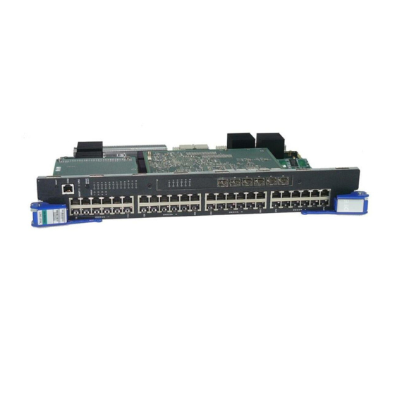
DFE-Platinum 7H4385-49 PoE Module DFE-Platinum 7H4385-49 PoE Module This section provides an overview of the 7H4385‐49 (Figure 1‐1). For information about the DFE module features and how to configure them, refer to the Enterasys Matrix DFE‐Platinum Series Configuration Guide. The 7H4385‐49 has 48, 10BASE‐T/100BASE‐TX, PoE‐compliant ports that are accessed through the fixed front panel RJ45 connectors. There is also an slot for an optional network expansion module (NEM). The DFE module can be installed in a Matrix E7, Matrix N1, Matrix N3, Matrix N5, or Matrix N7 chassis. The 7H4385‐49 DFE‐Platinum module also supports bridging between the Frame Transfer Matrix FTM1 and FTM2 backplanes in a Matrix E7 chassis. When mixing 6x1xxx, 6x2xxx, 6x3xxx, and 7H43xx‐xx series modules in a Matrix E7 chassis, certain hardware installation configuration rules must be followed to ensure proper operation. These rules are covered in “Module Placement and Installation Rules” on page 3‐4. Each of the fixed front panel ports can operate in either half‐duplex or full‐duplex mode of operation. The duplex mode can be determined by either auto‐negotiation or manual configuration. The DFE module ports can be configured to provide a high level of security, control traffic by limiting the rate of traffic accepted into the module and prioritizing traffic to expedite the flow of higher priority traffic through the module. For a complete list of capabilities, refer to the Enterasys Matrix DFE‐Platinum Series Configuration Guide. The DFE module receives power and backplane connectivity when it is inserted into the Matrix E7, Matrix N7, Matrix N5, Matrix N3, or Matrix N1 chassis. The power to support the DFE module connections to 802.3af PoE‐compliant 48 Vdc PDs (powered devices) can ... -
Page 24: 7H4385-49 Dfe-Platinum Module
DFE-Platinum 7H4385-49 PoE Module Figure 1-1 7H4385-49 DFE-Platinum Module FAST ENET 7H4385-49 À OFFLINE/ RESET Á Â Ã MGMT Ä Å GROUP SELECT GROUP Æ Ç È É 48V --- 20A MAX OPTIONAL POWER INPUT 1 OFFLINE/RESET switch GROUP STATUS LEDs 2 RJ45 COM port GROUP SELECT LEDs 3 MGMT LED... -
Page 25: Connectivity
With a NEM installed, the FTM bridging function is disabled. All ports remain active in either case. The fixed front panel ports can also support connections to PoE‐compliant PDs when the module is connected to an external N‐PoE Power system. Management Management of the module can be either in‐band or out‐of‐band. In‐band remote ® management is possible using Telnet, Enterasys Networks’ NetSight management application, or WebView™ application. Out‐of‐band management is provided through the RJ45 COM (Communication) port on the front panel using a VT100 terminal or a VT100 terminal emulator. Switch Configuration Using WebView Enterasys Networks’ HTTP‐based Web management application (WebView) is an intuitive web tool for simple management tasks. Switch Configuration Using CLI Commands The CLI commands enable you to perform more complete switch configuration ... -
Page 26: Secure Networks Policy Support
Secure Networks Policy Support Secure Networks Policy Support Policy Enabled Networking manages the allocation of networking infrastructure resources in a secure and effective manner. Using Secure Networks Policy, an IT Administrator can predictably assign appropriate resources to the Users, Applications, and Services that use the network; while blocking or containing access for inappropriate or potentially dangerous network traffic. Using this technology it is possible, for the first time, to align IT services with the needs of specific users and applications, and to leverage the network as a key component of the organization’s security strategy. The Secure Networks Policy Architecture consists of 3 components: Classification Rules, Network Services, and Behavioral Profiles. These are defined as follows: • Classification Rules determine how specific traffic flows (identified by Layer 2, Layer 3, and Layer 4 information in the data packet) are treated by each Switch or Router. In general, Classification Rules are applied to the networking infrastructure at the network edge/ingress point. • Network Services are logical groups of Classification Rules that identify specific networked applications or services. Users may be permitted or denied access to these services based on their role within the organization. Priority and bandwidth rate limiting may also be controlled using Network Services. • Behavioral Profiles (or roles) are used to assign Network Services to groups of users who share common needs–for example Executive Managers, Human Resources Personnel, or Guest Users. Access, resources, and security restrictions are applied as appropriate to each Behavioral Profile. A variety of authentication methods including 802.1X, EAP‐TLS, EAP‐TTLS, and PEAP may be used to classify and authorize each individual user; and the IT Administrator may also define a Behavioral Profile to apply in the absence of an authentication framework. LANVIEW Diagnostic LEDs LANVIEW diagnostic LEDs serve as an important troubleshooting aid by providing an easy way to observe the status of individual ports and overall network operations. 1-6 Introduction... -
Page 27: Chapter 2: Network Requirements
10BASE-T Network 100BASE-TX Network The network installation must meet the requirements to ensure satisfactory performance of this equipment. Failure to do so will produce poor network performance. The Enterasys Matrix DFE-Platinum Series Configuration Guide and the Cabling Guide referred to in the following sections can be found on the Enterasys Networks World Wide Web site: http://www.enterasys.com/support/manuals Refer to “Related Documents” on page xvi for additional information. -
Page 28: Module Placement In A Matrix E7 Chassis
Module Placement in a Matrix E7 Chassis In normal usage (and typical implementations) there is no need to enable/disable ports for Link Aggregation. The default values will result in the maximum number of aggregations possible. If the switch is placed in a configuration with its peers not running the protocol, no aggregations will be formed and the DFE modules will function normally (that is, Spanning Tree will block redundant paths). For details about the commands involved with configuring the Link Aggregation function, refer to the Enterasys Matrix DFE‐Platinum Series Configuration Guide. Module Placement in a Matrix E7 Chassis If you want to mix 6x1xxx, 6x2xxx, 6x3xxx, and 7H43xx‐xx series modules in the same Matrix E7 chassis, and successfully bridge data traffic to some or all modules in the chassis, it is necessary to have a bridging module (such as the 7H4385‐49) installed, and to follow the module placement rules described in “Module Placement and Installation Rules” on page 3‐4. FTM Bridge Function and Optional Interface Module The 7H4385‐49 DFE‐Platinum module does not support both the FTM bridging function and an optional NEM at the same time. With an optional NEM installed, the FTM bridging function is disabled. In either of these cases, all ports of the 7H4385‐49 remain active. 10BASE-T Network When connecting a 10BASE‐T segment to any of the RJ45 fixed front‐panel ports of the ... -
Page 29: 100Base-Tx Network
100BASE-TX Network 100BASE-TX Network The fixed front panel ports of the 7H4385‐49 provide a connection that supports Category 5 UTP cabling. The device at the other end of the twisted pair segment must meet IEEE 802.3‐2002 100BASE‐TX Fast Ethernet network requirements for the devices to operate at 100 Mbps. The fixed front‐panel ports also support the 802.3af‐2003 standard for Power over Ethernet (PoE) power sourcing applications over existing cabling. For more information about PoE, refer to Appendix Note: The fixed ports of the module support Category 5 UTP cabling with an impedance between 85 and 111 ohms for 100 Mbps operation. The module is capable of operating at either 10 or 100 Mbps. The module automatically senses the speed of the other device and adjusts its speed accordingly. - Page 30 100BASE-TX Network 2-4 Network Requirements...
-
Page 31: Important Notice
Installation Electrical Hazard: Only qualified personnel should perform installation procedures. Riesgo Electrico: Solamente personal calificado debe realizar procedimientos de instalacion. Elektrischer Gefahrenhinweis: Installationen sollten nur durch ausgebildetes und qualifiziertes Personal vorgenommen werden. Important Notice Read the Release Notes shipped with the DFE module to check for any exceptions to the supported features and operation documented in this guide. -
Page 32: Installation Site Requirement
Sicherungen geschützt und durch einen Verantwortlichen kontrolliert werden. Unpacking the DFE Module Unpack the DFE module as follows: Open the box and remove the packing material protecting the DFE module. Verify the contents of the carton as listed in Table 3‐1. Table 3-1 Contents of 7H4385-49 Module Carton Item Quantity 7H4385-49 Installation Guide Customer Release Notes Remove the tape seal on the non‐conductive bag to remove the DFE module. Perform a visual inspection of the DFE module for any signs of physical damage. Contact Enterasys Networks if there are any signs of damage. Refer to “Getting Help” on page xviii for details. 3-2 Installation... -
Page 33: Installing Optional Network Expansion Module (Nem)
Installing Optional Network Expansion Module (NEM) Note: Install any optional equipment before proceeding to “Backplane Connections and Installation Rules” on page 3-3 for an explanation of the rules to install different series modules in a Matrix E7 chassis. Refer to your release notes or the Enterasys Networks web site for the latest available network expansion module. A Phillips screwdriver is required to install an optional network expansion module into the 7H4385‐49. Installing a NEM involves •... -
Page 34: Module Placement And Installation Rules
Backplane Connections and Installation Rules These DFE modules have connections to both FTM1 and FTM2 backplanes, enabling them to route frames between the two backplanes and all modules in the 6C107 chassis. However, the older first (6x1xx), second (6x2xx), and third (6x3xx) generation modules are still managed using their own Local Management and are not subject to management by the DFE module management entity. The Matrix N1 (7C111), Matrix N3 (7C103) and Matrix N7 (7C107) chassis have only FTM2 connections and support only DFE modules. The Matrix N5 (7C105‐P) has FTM2 connections and also supports PoE‐compliant DFE modules. Module Placement and Installation Rules The DFE‐Platinum modules can be installed in a Matrix E7 (refer to “Matrix E7 Chassis Module Placement,” below, for placement rules), Matrix N1, Matrix N3, Matrix N5, or Matrix N7 chassis. The Matrix N1, Matrix N3, Matrix N5, and Matrix N7 chassis support only DFE Series modules and there are no particular rules for installing modules. Matrix E7 Chassis Module Placement Depending on the modules being installed in the Matrix E7 chassis and to help ensure ... - Page 35 Backplane Connections and Installation Rules Example 2 (Figure 3-1, Shows the chassis fully populated with third generation modules (6x3xx). These modules can also be installed in any available chassis slot in the Matrix E7 chassis, but operate as individual modules with separate IP addresses. Each module is configured using Local Management. Rule: The 6x3xx modules can be installed in any available chassis slot in the Matrix E7 chassis. Example 3 (Figure 3-1, C) Shows chassis slots 1 through 5 populated with first and second generation modules (6x1xx and 6x2xx). If a 6x1xx or 6x2xx series module is installed in slot 6 or 7, it will operate in standalone mode (no backplane connectivity). Like the 6x3xx modules, the 6x1xx and 6x2xx modules operate as individual modules with separate IP addresses, and each one is configured using Local Management. Rule: The 6x1xx and 6x2xx modules can communicate with each other when they are installed in chassis slots 1 through 5 in the Matrix E7 chassis. If installed in slot 6 or 7, they operate in standalone mode. Example 4 (Figure 3-1, Shows chassis slots 1 through 5 populated with a mix of 6x1xx, 6x2xx, and 6x3xx modules and only third generation modules in slots 6 and 7. In this module arrangement, the 6x3xx module provides a proxy bridge, which enables the 6x1xx and 6x2xx modules to communicate with 6x3xx modules in slot 6 or 7. If more than one 6x3xx module is installed in slots 1 to 5, the module in the lowest numbered slot performs the proxy function for slots 6 and 7. Therefore, if a 6x3xx module is already ...
- Page 36 Backplane Connections and Installation Rules Example 5 (Figure 3-1, E) Shows chassis slots 1 and 5 populated with 6x2xx and 6x1xx modules, respectively; slots 2 through 4 with DFE modules without a bridging module; and slots 6 and 7 with 6x3xx modules. In this module arrangement, the 6x2xx and 6x1xx modules in slots 1 and 5 can only communicate with each other, because there is no 6x3xx module in one of the first five slots to serve as the proxy bridge to communicate with the 6x3xx modules in slots 6 and 7. The 7x4xxx DFE modules in slots 2, 3, and 4 will operate under one IP address. Since there is no DFE bridging module, the DFE modules will not communicate with any other modules in the chassis. Rule: In this example, there must be at least one 6x3xx series module, and a bridging module in any of the slots 1 through 5 to enable communications between all generations of modules in the chassis. Example 6 (Figure 3-1, F) The module arrangement in this example is similar to the one shown in Figure 3‐1, E described in Example 5. The only difference is that one of the bridging modules (7H4382‐25, 7H4382‐49, 7H4383‐49, or 7H4385‐49) is installed in slot 2, enabling all modules to communicate with each other. The 7H4382‐49 is used in this example. Rule: In this example, the bridging module serves as both the FTM1‐to‐FTM2 bridge and the five‐to‐seven slot proxy bridge. The 6x3xx does not serve as a proxy bridge in this configuration because the bridging module is in a slot with a lower number. 3-6 Installation...
-
Page 37: Preparing To Install Into A Matrix E7, N1, N3, N5, Or N7 Chassis
Preparing to Install into a Matrix E7, N1, N3, N5, or N7 Chassis Preparing to Install into a Matrix E7, N1, N3, N5, or N7 Chassis Caution: Failure to observe static safety precautions could cause damage to the module. Follow static safety handling rules and wear the antistatic wrist strap. Do not cut the non-conductive bag to remove the module. -
Page 38: Installing The 7H4385-49 Into A Matrix E7 Or Matrix N7 Chassis
Preparing to Install into a Matrix E7, N1, N3, N5, or N7 Chassis Examine the module for damage. If any damage exists, DO NOT install the module. Immediately contact Enterasys Networks. Refer to “Getting Help” on page xviii. To install a 7H4385‐49 into a Matrix E7 or Matrix N7, proceed to “Installing the 7H4385‐49 into a Matrix E7 or Matrix N7 Chassis” on page 3‐8. For Matrix N1, Matrix N3, or Matrix N1, refer to “Installing the 7H4385‐49 into Matrix N1, N3, or N5 Chassis” on page 3‐11. Installing the 7H4385-49 into a Matrix E7 or Matrix N7 Chassis To install the 7H4385‐49, refer to Figure 3‐2 and proceed as follows: Caution: To prevent damaging the backplane connectors in the following step, take care... - Page 39 Preparing to Install into a Matrix E7, N1, N3, N5, or N7 Chassis Align the module card between the upper and lower card guides of the desired slot and slide it into the chassis, taking care that the module slides in straight. See Caution below. Caution: Due to the amount of force needed to properly seat the module connectors into the backplane connectors, it is best to apply force to the end of the levers to insert (or eject) the module.
-
Page 40: Installing Module Into Matrix E7 Or N7 Chassis (Matrix E7 Shown)
Preparing to Install into a Matrix E7, N1, N3, N5, or N7 Chassis Figure 3-2 Installing Module into Matrix E7 or N7 Chassis (Matrix E7 shown) Æ Á SERIES Ä FAST ENET 7H4385-49 OFFLINE/ RESET MGMT GROUP SELECT GROUP 12 X Å... -
Page 41: Installing The 7H4385-49 Into Matrix N1, N3, Or N5 Chassis
Preparing to Install into a Matrix E7, N1, N3, N5, or N7 Chassis Installing the 7H4385-49 into Matrix N1, N3, or N5 Chassis Caution: Failure to observe static safety precautions could cause damage to the module. Follow static safety handling rules and wear the antistatic wrist strap. Do not cut the non-conductive bag to remove the module. - Page 42 Preparing to Install into a Matrix E7, N1, N3, N5, or N7 Chassis Align the module card between the upper and lower card guides of the desired slot and slide it into the chassis, taking care that the module slides in straight. See Caution below. Caution: Due to the amount of force needed to properly seat the module connectors into the backplane connectors, it is best to apply force to the end of the levers to insert (or eject) the module.
-
Page 43: Installing Module Into Matrix N3, N5, Or N1 Chassis (N3 Shown)
Preparing to Install into a Matrix E7, N1, N3, N5, or N7 Chassis Figure 3-3 Installing Module into Matrix N3, N5, or N1 Chassis (N3 shown) Æ Á 7C203-1 REDUNDANCY 100-125V~12.0A 200-240V~6.0A 50/60 Hz 7C203-1 REDUNDANCY 100-125V~12.0A 200-240V~6.0A 50/60 Hz Ä... -
Page 44: Connecting 48 Vdc Power For Poe Operation
Connecting 48 Vdc Power for PoE Operation Connecting 48 Vdc Power for PoE Operation The Matrix N5 (7C105‐P) chassis provides 48 Vdc to connected PDs (powered devices) by way of its backplane connection to a PoE‐compliant DFE module such as the 7H4385‐49. Note: When you install the 7H4382-49 in a Matrix N5 chassis 7H4382-49 48 Vdc , the Optional Power Input does not support a connection from an external N-POE Power System. -
Page 45: Connecting To The Network
Connecting to the Network Connecting to the Network This section provides the procedures for connecting unshielded twisted pair (UTP) segments from the network or other devices to the 7H4385‐49 (“Connecting UTP Cables to 7H4385‐49” on page 3‐15). Note: If the DFE module is being installed in a network using Link Aggregation, there are rules concerning the network cable and port configurations that must be followed for Link Aggregation to operate properly. -
Page 46: Connecting A Twisted Pair Segment With Rj45 Connector
Connecting to the Network Making the UTP Connections Caution: To prevent damage to the equipment, do not connect the PoE supported ports (1 through 48) to segments running between buildings. Keep connections to equipment within the building. Precaución: Para evitar que el equipo se dañe, no conecte los puertos PoE (1 a 48) a segmentos que vayan de un edificio a otro. -
Page 47: Four-Wire Crossover Cable Rj45 Pinouts, Connections Between Hub Devices
Connecting to the Network b. Each time the GROUP SELECT button is pressed for less that one second, the GROUP LED lights up in sequence, indicating which Group is selected. The receive and transmit activity for that group of segments is then indicated by the RX and TX LEDs for each segment. Verify that the cabling being used is Category 5 UTP with an impedance between 85 and 111 ohms. If the port is to operate at 100 Mbps, category 5 cabling must be used. d. Verify that the device at the other end of the twisted pair segment is on, and properly connected to the segment. Verify that the RJ45 connectors on the twisted pair segment have the proper pinouts and check the cable for continuity. Typically, a crossover cable is used between hub devices. A straight‐through cable is used to connect between switches or hub devices and an end user (computer). Refer to Figure 3‐5 and Figure 3‐6 for four‐wire RJ45 connections. Refer to Figure 3‐7 and Figure 3‐8 for eight‐wire RJ45 connections. Figure 3-5 Four-Wire Crossover Cable RJ45 Pinouts, Connections Between Hub Devices À Á... -
Page 48: Four-Wire Straight-Through Cable Rj45 Pinouts, Connections Between Switches And End User Devices
Connecting to the Network Figure 3-6 Four-Wire Straight-Through Cable RJ45 Pinouts, Connections Between Switches and End User Devices À Á RX– RX– Ã TX– TX– Â 1 RJ45 device port 3 RJ45-to-RJ45 straight-through cable 2 Other device port 4 RX+/RX- and TX+/TX- connections. These connections must share a common color pair. -
Page 49: Eight-Wire Straight-Through Cable Rj45 Pinouts, Connections Between Switches And End User Devices
Connecting to the Network Figure 3-8 Eight-Wire Straight-Through Cable RJ45 Pinouts, Connections Between Switches and End User Devices À Á TX1+ TX2+ RX1- RX2- TX2+ TX1+ TX3+ TX4+ RX3- RX4- RX2- RX1- TX4+ TX3+ RX4- RX3- Â 1 RJ45 device port 3 RJ45-to-RJ45 straight-through cable 2 Other device port Ensure that the twisted pair connection meets the dB loss and cable specifications ... -
Page 50: Connecting To Com Port For Local Management
Connecting to COM Port for Local Management Press on the GROUP SELECT switch again for more than one second. This returns the 7H4385‐49 to port RX (receive) and TX (transmit) status mode. Connecting to COM Port for Local Management This section describes how to install a UTP straight‐through cable with RJ45 connectors and optional adapters to connect a PC, a VT series terminal, or a modem to an Enterasys Networks module to access Local Management. This section also provides the pinout assignments of the adapters. What Is Needed The following is a list of the user‐supplied parts that may be needed depending on the connection: • RJ45‐to‐DB9 female adapter • UTP straight‐through cable terminated at both ends with RJ45 connectors • RJ45‐to‐DB25 female adapter • RJ45‐to‐DB25 male adapter Using a UTP straight‐through cable and an RJ45‐to‐DB9 adapter, you can connect products equipped with an RJ45 COM port to an IBM or compatible PC running a VT series emulation software package. Using a UTP straight‐through cable and an RJ45‐to‐DB25 female adapter, you can connect products equipped with an RJ45 COM port to a VT series terminal or VT type terminals running emulation programs for the VT series. -
Page 51: Connecting To A Vt Series Terminal
1 UTP straight-through cable with RJ45 connectors 3 RJ45-to-DB9 PC adapter 2 RJ45 COM port 4 IBM PC or compatible device Connecting to a VT Series Terminal To connect a VT Series terminal to an Enterasys Networks DFE module COM port (Figure 3‐10), use a UTP straight‐through cable with RJ45 connectors and an RJ45‐to‐DB25 female adapter, and proceed as follows: Connect the RJ45 connector at one end of the UTP straight‐through cable to the COM port on the Enterasys Networks module. DFE-Platinum Series Hardware Installation Guide 3-21... -
Page 52: Connecting To A Modem
MGMT GROUP SELECT GROUP Á Ã Â À 1 UTP straight-through cable with RJ45 connectors 3 RJ45-to-DB25 VT adapter 2 RJ45 COM port 4 VT series terminal Connecting to a Modem To connect a modem to an Enterasys Networks DFE module COM port (Figure 3‐11), use a UTP straight‐through cable with RJ45 connectors and an RJ45‐to‐DB25 male adapter, and proceed as follows: 3-22 Installation... -
Page 53: Connecting To A Modem
Connecting to COM Port for Local Management Connect the RJ45 connector at one end of the UTP straight‐through cable to the COM port of the module. Plug the RJ45 connector at the other end of the UTP straight‐through cable into the RJ45‐to‐DB25 modem adapter. Connect the RJ45‐to‐DB25 adapter to the communications port on the modem. Turn on the modem. With a PC connected to a remote modem, you can configure the switch remotely. To accomplish this, you must configure your PC VT emulation package with the following parameters. Parameter Setting Mode 7 Bit Control Transmit Transmit=9600 Bits Parity 8 Bits, No Parity Stop Bit 1 Stop Bit When these parameters are set, the Local Management password screen will display. Refer to the Enterasys Matrix DFE‐Platinum Series Configuration Guide for further information. Figure 3-11 Connecting to a Modem FAST ENET 7H4385-49... -
Page 54: Adapter Wiring And Signal Assignments
Connecting to COM Port for Local Management Adapter Wiring and Signal Assignments COM Port Adapter Wiring and Signal Diagram RJ45 Conductor Signal Blue Receive (RX) Transmit (TX) Green Ground (GRD) Orange Request to Send (RTS) Yellow Clear to Send (CTS) Pins Pins RJ45 Connector (Female) - Page 55 Connecting to COM Port for Local Management VT Series Port Adapter Wiring and Signal Diagram RJ45 DB25 Conductor Signal Transmit (TX) Blue Receive (RX) Yellow Clear to Send (CTS) Green Ground (GRD) Orange Data Terminal Ready Pins Pins RJ45 Connector (Female) DB25 Connector (Female) Modem Port Adapter Wiring and Signal Diagram RJ45...
-
Page 56: Completing The Installation
Completing the Installation Completing the Installation Completing the DFE module installation depends on if the module is being installed in: • a new DFE module system (refer to “Completing the Installation of a New System” on page 3‐26), or • an established, operating DFE module system (refer to “Completing the Installation of a DFE Module in an Existing System” on page 3‐28). Completing the Installation of a New System In a new system of DFE modules, one of the installed DFE modules will become the management module on chassis power up, and all DFE modules will automatically be set to the factory default values. A complete list of the factory default values are provided in Chapter 3 of the Enterasys Matrix DFE‐Platinum Series Configuration Guide. After installing all DFE modules into the host chassis and making the connections to the network, proceed to the following First‐Time Log‐In Using a Console Port Connection procedure to access the module management startup screen from your PC, terminal, or modem connection. First-Time Log-In Using a Console Port Connection Notes: This procedure applies only to initial log-in, and to logging in to a device not yet configured with administratively-supplied user and password settings. -
Page 57: Matrix Dfe Startup Screen Example (N7 Chassis)
Enterasys Networks, Inc. 50 Minuteman Rd. Andover, MA 01810-1008 U.S.A. Phone: +1 978 684 1000 E-mail: support@enterasys.com WWW: http://www.enterasys.com (c) Copyright Enterasys Networks, Inc. 2003 Chassis Serial Number: xxxxxxxxxxxx Chassis Firmware Revision: xx.xx.xx Matrix N7(su)-> DFE-Platinum Series Hardware Installation Guide 3-27... -
Page 58: Completing The Installation Of A Dfe Module In An Existing System
Completing the Installation Completing the Installation of a DFE Module in an Existing System In an established DFE module system, • a DFE module is already established as the management module, • the passwords have already been set for various users, • the system IP address is set, and • other system parameters have been set. When you install a new DFE module into a system with an existing configured user account, the current system settings in that account are already recognized by the new DFE module and it will operate accordingly. If you need to change any settings, you can connect a terminal to the local console port as described in “Connecting to COM Port for Local Management” on page 3‐20 to access system management, or use a Telnet connection to access the DFE module system management as described in Chapter 3 of the Enterasys Matrix DFE‐Platinum Series Configuration Guide. Logging in with an Administratively-Configured User Account If the device’s default user account settings have been changed, proceed as follows: At the login prompt, enter your administratively‐assigned user name and press ... -
Page 59: Chapter 4: Troubleshooting
Troubleshooting This chapter provides information concerning the following: For information about... Refer to page... Using LANVIEW Troubleshooting Checklist Overview of DFE Module Shutdown Procedure Recommended Shutdown Procedure Using OFFLINE/RESET Switch Last Resort Shutdown Procedure Using OFFLINE/RESET Switch 4-10 Using LANVIEW The DFE module uses a built‐in visual diagnostic and status monitoring system called LANVIEW. The LANVIEW LEDs (Figure 4‐1) allow quick observation of the network status to aid in diagnosing network problems. About the Management (MGMT) LED The MGMT LED (shown in Figure 4‐1) indicates when the module is serving as the ... -
Page 60: Viewing The Receive And Transmit Activity
Using LANVIEW Viewing the Receive and Transmit Activity You can view the 7H4385‐49 receive and transmit port activity on the RX and TX LEDs. However, only one group of 12 ports may be viewed at a time. To view the receive and transmit activity on a group of 7H4385‐49 segments, press the GROUP SELECT button (see Figure 4‐1) for less than one second to step to the group of interest (Groups 1 through 4). Each time the GROUP SELECT button is pressed for less than one second, the GROUP LED lights up in sequence, indicating which group is selected. The receive and transmit activity for that group of segments is then indicated by the RX and TX LEDs for each port. Figure 4-1 LANVIEW LEDs FAST ENET 7H4385-49 À RESET GROUP SELECT MGMT GROUP GROUP SELECT GROUP Á RX TX 1 MGMT LED 2 Group 1, Port 1 LEDs Viewing the PoE Port Status If the 7H4385‐49 is installed in an N5 chassis or is receiving 48 Vdc from an external ... -
Page 61: Lanview Leds
Power off. Ensure chassis has adequate power. Amber Blinking. DFE module in None. process of booting. Solid. Testing. If the LED remains amber for several minutes, contact Enterasys Networks for technical support. Green Blinking. Image starts None. running. Solid. Functional. None. - Page 62 Amber Flashing. Link present, port None. enabled, traffic is being received by the interface. Blinking. Indicates Contact Enterasys Networks for collisions. This indication is technical support. only supported on 10/100 ports. Port enabled, but no activity. If it is known that the port should be...
- Page 63 Power Classification. according to 802.3af 2. Check Ethernet cable from the PD standard PoE device power for short circuits. classification. 3. Contact Enterasys Networks for technical support. Red/Off Port is off due to PoE power None management. Port may be...
-
Page 64: Troubleshooting Checklist
Troubleshooting Checklist Troubleshooting Checklist If the module is not working properly, refer to Table 4‐2 on page 4‐6 for a checklist of problems, possible causes, and recommended actions to resolve the problem. Table 4-2 Troubleshooting Checklist Problem Possible Cause Recommended Action All LEDs are OFF. Loss of power. Ensure that the DFE module was installed properly according to the installation instructions in Chapter 3, and that the host chassis is providing power. - Page 65 Verify that all network connections between the network management station and the DFE module are valid and operating. If the problem continues, contact Enterasys Networks for technical support. Port(s) goes into Loop condition detected. Verify that Spanning Tree is enabled. standby for no Refer to the Enterasys Matrix apparent reason.
-
Page 66: Overview Of Dfe Module Shutdown Procedure
DFE module. cycled, the front switch, causing the user- If the problem continues, contact panel OFFLINE/ entered parameters to reset to Enterasys Networks for technical support. RESET switch was factory default settings. pressed. Clear Persistent Data that was set through Local Management. -
Page 67: Recommended Shutdown Procedure Using Offline/Reset Switch
Overview of DFE Module Shutdown Procedure Figure 4-2 OFFLINE/RESET Switch FAST ENET À 7H4385-49 OFFLINE/ RESET MGMT GROUP SELECT GROUP 1 OFFLINE/RESET switch (in similar location on all DFE modules) Recommended Shutdown Procedure Using OFFLINE/RESET Switch Caution: Do not pull any DFE module out of an operating chassis before it has completed its shutdown routine. -
Page 68: Last Resort Shutdown Procedure Using Offline/Reset Switch
Overview of DFE Module Shutdown Procedure Last Resort Shutdown Procedure Using OFFLINE/RESET Switch Caution: This method of shutting down a DFE module is not recommended except as a last resort, because all processes currently running on the module will be interrupted resulting in loss of frames. -
Page 69: Appendix A: Specifications
Specifications This appendix provides information about the following: For information about... Refer to page... DFE Module Specifications COM Port Pinout Assignments Regulatory Compliance Enterasys Networks reserves the right to change the specifications at any time without notice. DFE Module Specifications Table A‐1 provides the Input/Output ports, processors and memory, physical, and environmental module specifications for the 7H4385‐49 DFE module. Table A-1 7H4385-49 Specifications Item Specification Ports 1 through 48 Forty-eight, 10BASE-T/100BASE-TX ports by way of RJ45 connectors. -
Page 70: Com Port Pinout Assignments
COM Port Pinout Assignments Table A-1 7H4385-49 Specifications (continued) Item Specification Physical Dimensions 46.43 H x 6.05 W x 29.51 D (cm) 18.28 H x 2.38 W x 11.62 D (in.) Approximate Weight Gross: 5.54 kg (12.0 lb) (shipping carton containing one module) Net: 4.10 kg (9.0 lb) (one module without packaging) -
Page 71: Regulatory Compliance
Regulatory Compliance Regulatory Compliance The 7H4385‐49 meets the safety and electromagnetic compatibility (EMC) requirements listed in Table A‐3: Table A-3 Compliance Standards Regulatory Compliance Standards Safety UL 60950, CSA C22.2 No. 60950, 73/23/EEC, EN 60950, IEC 60950, EN 60825, 21 CFR 1040.10 Electromagnetic Compatibility (EMC) 47 CFR Parts 2 and 15, CSA C108.8, 89/336/EEC, EN 55022, EN 61000-3-2, EN 61000-3-3, EN 55024, AS/NZS CISPR 22, VCCI V-3 ‡FE-Platinum Series Hardware Installation Guide A-3... - Page 72 Regulatory Compliance A-4 Specifications...
-
Page 73: Appendix B: Mode Switch Settings And Option Installations
Mode Switch Settings and Option Installations This appendix covers the following items: For information about... Refer to page... Required Tools Setting the Mode Switches Memory Locations and Replacement Procedures Gaining Access to Memory Modules Required Tools Use the following tools to perform the procedures provided in this appendix: • Antistatic wrist strap • Phillips screwdriver Caution: An antistatic wrist strap is required to perform the procedures in this appendix. Use the antistatic wrist strap shipped with chassis when performing any of the procedures in this appendix to minimize ESD damage to the devices involved. -
Page 74: Setting The Mode Switches
Precaución: Si desea modificar la configuración del interruptor, lea las secciones correspondientes para saber cuál será el resultado de hacerlo. Estas modificaciones a la configuración sólo debe realizarlas personal calificado. Figure B‐1 shows the location of the mode switches and the switch settings for normal operation. These switches are set at the factory and rarely need to be changed. Switch definitions and positions are as follows: • Switches 1 through 6 – For Enterasys Networks use only. • Switch 7 – Clear Persistent Data. Changing the position of this switch clears Persistent Data on the next power‐up of the module. All user‐entered parameters, such as the IP address, module names, etc., are reset to the factory default settings. Once the module resets, you can either use the factory default settings or reenter your own parameters. • Switch 8 – Clear Admin Password. Changing the position of this switch clears the ... -
Page 75: Memory Locations And Replacement Procedures
Mode Switch Location (7H4385-49 shown without safety cover) À 1 2 3 4 5 6 7 8 1 Mode switch pack (7H4385-49 shown without safety cover) Memory Locations and Replacement Procedures If the Dual In‐line Memory Module (DIMM) or DRAM Single In‐line Memory Module (SIMM) (FLASH memory) needs to be replaced, the following sections describe how to access, locate, and replace these memory modules. If you have questions concerning the replacement of either memory module, refer to “Getting Help” on page xviii for details on how to contact Enterasys Networks. Figure B‐2 shows the DIMM and DRAM SIMM locations on the main PC board. DFE-Platinum Series Hardware Installation Guide B-3... -
Page 76: Gaining Access To Memory Modules
Gaining Access to Memory Modules Figure B-2 DIMM and DRAM SIMM Locations (7H4385-49 shown without safety cover) Â Á À 1 DRAM SIMM 2 DIMM 3 Main PC board Gaining Access to Memory Modules Before you can replace the DRAM SIMM, you must gain access to it by removing the safety cover and the network expansion module, if one is installed. To gain access to the DIMM, you only need to remove the safety cover. Electrical Hazard: To prevent exposure to an energy hazard in a 7H4385-49 connected to an external N-POE Power System, disconnect the 48-Vdc power cable from the 48-Vdc input connector before servicing or removing the 7H4385-49. -
Page 77: Removing The Safety Cover
Gaining Access to Memory Modules Removing the Safety Cover Warning: The safety cover protects you from exposure to an energy hazard in excess of 240 Volt-Amperes. Never operate the DFE module without the safety cover installed. Advertencia: La cubierta de seguridad lo protege de exponerlo al riesgo de energía en exceso de 240 Volt -Amperes.Nunca se debe opererar el modulo de DFE sin la cobertura de seguridad instalada. -
Page 78: Removing The Safety Cover
Gaining Access to Memory Modules Figure B-3 Removing the Safety Cover Á À Â Ã 1 Safety cover 3 Standoffs (7) 2 Cover screws (7) 4 Standoff/spacer screwed to standoff under the NEM B-6 Mode Switch Settings and Option Installations... -
Page 79: Dram Simm Replacement Procedure
Gaining Access to Memory Modules DRAM SIMM Replacement Procedure Caution: Observe all Electrostatic Discharge (ESD) precautions when handling sensitive electronic equipment. Precaución: Al trabajar con equipos electrónicos sensibles, tome todas las precauciones de seguridad para evitar descargas de electricidad estática. After you have removed the safety cover as described in “Removing the Safety Cover” on ... -
Page 80: Removing The Existing Dram Simm
Gaining Access to Memory Modules Remove the two screws fastening the NEM to the DFE module front panel and remove the standoff fastening the NEM to the main board. Save the two screws and standoff for later use to reinstall the NEM. Lift and remove the NEM off the two main PC board connectors. Now you have access to the DRAM SIMM. To replace the DRAM SIMM, proceed to “Removing the DRAM SIMM”. Removing the DRAM SIMM To remove the DRAM SIMM, refer to Figure B‐5 and proceed as follows. Refer to Figure B‐5. Push the connector arms away from the DRAM SIMM to release it from the connector. Note: The ejector arms on this connector are not spring-loaded, so they will remain in the open position until manually closed. Remove the DRAM SIMM from the connector. -
Page 81: Installing The Dram Simm
Gaining Access to Memory Modules Installing the DRAM SIMM Caution: Observe all Electrostatic Discharge (ESD) precautions when handling sensitive electronic equipment. Precaución: Al trabajar con equipos electrónicos sensibles, tome todas las precauciones de seguridad para evitar descargas de electricidad estática. To install the DRAM SIMM, refer to Figure B‐6 and proceed as follows: With the connector arms set in the open position, insert the DRAM SIMM between the ... -
Page 82: Dimm Replacement Procedure
Gaining Access to Memory Modules DIMM Replacement Procedure In the event that the Dual In‐line Memory Module (DIMM) needs to be replaced, the following sections explain how to remove and install the DIMM. If you have questions concerning the replacement of the DIMM, refer to “Getting Help” on page xviii for details on how to contact Enterasys Networks. Removing the DIMM Caution: Observe all Electrostatic Discharge (ESD) precautions when handling sensitive electronic equipment. Precaución: Al trabajar con equipos electrónicos sensibles, tome todas las precauciones de seguridad para evitar descargas de electricidad estática. -
Page 83: Installing The Network Expansion Module (Nem
Gaining Access to Memory Modules Installing the DIMM Caution: Observe all Electrostatic Discharge (ESD) precautions when handling sensitive electronic equipment. Precaución: Al trabajar con equipos electrónicos sensibles, tome todas las precauciones de seguridad para evitar descargas de electricidad estática. To install a DIMM, refer to Figure B‐8 and proceed as follows: Insert the DIMM down between the connector fingers. -
Page 84: Installing The Network Expansion Module
Gaining Access to Memory Modules Figure B-9 Installing the Network Expansion Module  À Å Á Ä Ã 1 NEM 3 NEM connectors 5 Coverplate screws (2) 2 Front panel 4 Main board connectors 6 Standoff Use two of the saved coverplate screws to fasten the NEM to the DFE module front panel, but do not tighten screws at this time. Insert the saved standoff through the NEM to the standoff on the main board. Screw in the standoff, but do not tighten screws at this time. ... -
Page 85: Reinstalling The Safety Cover
Gaining Access to Memory Modules Reinstalling the Safety Cover To install the safety cover, refer to Figure B‐10 and proceed as follows: Warning: The safety cover protects you from exposure to an energy hazard in excess of 240 Volt-Amperes. Never operate the DFE module without the safety cover installed. Advertencia: La cubierta de seguridad lo protege de exponerlo al riesgo de energía en exceso de 240 Volt -Amperes.Nunca se debe opererar el modulo de DFE sin la cobertura de seguridad instalada. -
Page 86: Installing The Safety Cover
Gaining Access to Memory Modules Figure B-10 Installing the Safety Cover Á À Â Safety cover Screws (7) Standoff (7) B-14 Mode Switch Settings and Option Installations... -
Page 87: Appendix C: About Poe (Power Over Ethernet)
About PoE (Power over Ethernet) This appendix provides an overview of Power over Ethernet Technology and how it is implemented in relation to the 7H4385‐49. Overview Power over Ethernet (PoE) refers to the ability to provide operational power through the same Ethernet cabling to a PD (powered device) connected to a data network. Modern Ethernet implementations employ differential signals over twisted pair cables. This requires a minimum of two twisted pairs for a single physical link. Both ends of the cable are isolated with transformers blocking any DC or common mode voltage on the signal pair. PoE exploits this fact by using two twisted pairs as the two conductors to supply a direct current. One pair carries the power supply current and the other pair provides a path for the return current. While several proprietary legacy implementations of PoE have been deployed by LAN equipment vendors, in 2003 the IEEE published the IEEE 802.3af‐2003 specification, which is part of the 802.3 suite of standards. The 7H4385‐49 is fully compliant with the IEEE 802.3af standard. It supports the standard resistor based detection method, as well as AC disconnect capability. The 7H4385‐49 is also capable of supplying the maximum specified current to all ports simultaneously. Each PD has a PDC (Powered Device Classification) that is transmitted to the DFE module for power management purposes. Table C‐1 lists the classifications and the associated power ranges. Table C-1 Powered Device Classifications Class Usage PD Maximum Power Range Usage Default 0.44 to 12.95 Watts Optional 0.44 to 3.84 Watts Optional... -
Page 88: Proprietary Pd Detection
Overview Proprietary PD Detection The 7H4385‐49 supports a subset of the currently deployed proprietary PoE methods. This includes support for Cisco PDs, including a proprietary capacitor based detection scheme. Power Interface The 7H4385‐49 can interface with an external 48V power supply that resides in a Matrix N5 chassis or from a separate Matrix N‐POE Power System. Matrix N5 Backplane 48 Vdc Interface The 7H4385‐49 has a connector that interfaces with the backplane of the N5 chassis for 48 Vdc power. This power connection on the 7H4385‐49 is fused, has EMI suppression components for this interface, and can support a sustained output current of 20 A. Front Panel 48 Vdc Interface The 48 Vdc Optional Power Input connector on the 7H4385‐49 front panel provides a power interface connection for an Enterasys Matrix N‐POE Power System, which provides the 48 Vdc, 20 Amperes of power and return as well as the power supply status signals. The status signals indicate the presence and operating state of each Matrix N‐POE Power System power supplies. This 48 Vdc Optional Power Input interface is not fused as the N‐PoE Power System has a circuit breaker for each PoE switch module power feed. Warning: The DFE module is shipped with a cover over its 48 Vdc Optional Power Input connector. -
Page 89: Poe Port Status Leds
Overview PoE Port Status LEDs The PoE port status of each 10/100 Mbps front‐panel port is indicated by the two‐color RX and TX LED display for each port. To observe the PoE port status indications, you must switch the DFE module management system from the default RX/ TX Status Mode to the PoE Port Status Mode using the DFE module front‐panel GROUP SELECT switch. The switch operation and a description of how to use the LED indications are described in “Using LANVIEW” on page 4‐1. Table C‐2 provides a brief description of each port status RX/TX LED display. Table C-2 PoE Status LED Indications PoE Port Status RX LED TX LED Port is powered on GREEN Port is off due to overload Port is off due to power management Port is off for other reason DFE-Platinum Series Hardware Installation Guide C-3... - Page 90 Overview C-4 About PoE (Power over Ethernet)
- Page 91 Index Numerics 100BASE-TX Getting Help connection 3-15 instructions for xviii requirements GROUP SELECT button 10BASE-T use of the connection 3-15 requirements Installation 7H4385-49 connecting to the Network 3-15 introduction to 1-3, module into Matrix E7 or N7 chassis specifications for module into Matrix N1, N3, N5 chassis 3-11 optional network expansion module...
- Page 92 Network Requirements list of Safety requirements Notices Specifications General 7H4385-49 Standards compatibility Offline/reset switch use of Transmit LEDs Optional network expansion module viewing of installation of Troubleshooting checklist for Pinout assignments console port Unpacking the module Pinouts User Personalized Networks (UPN) See Secure crossover 3-17, 3-18 Networks Policy Support.
Need help?
Do you have a question about the MATRIX 7H4385-49 and is the answer not in the manual?
Questions and answers