Table of Contents
Advertisement
Quick Links
Advertisement
Table of Contents
Troubleshooting

Related Manuals for Thermo Scientific GENESYS 20


Summary of Contents for Thermo Scientific GENESYS 20
- Page 1 Artisan Technology Group is your source for quality new and certified-used/pre-owned equipment SERVICE CENTER REPAIRS WE BUY USED EQUIPMENT • FAST SHIPPING AND DELIVERY Experienced engineers and technicians on staff Sell your excess, underutilized, and idle used equipment at our full-service, in-house repair center We also offer credit for buy-backs and trade-ins •...
- Page 2 ™ GENESYS SPECTROPHOTOMETER SERVICE MANUAL...
- Page 3 ™ GENESYS SPECTROPHOTOMETER SERVICE MANUAL...
- Page 4 Copyright © 1998-2002, Thermo Spectronic All rights reserved.
- Page 5 This service manual contains information, instructions, and specifications for the ™ GENESYS 20 spectrophotometer that were believed accurate at the time this manual was written. However, as part of Thermo Spectronic’s on-going program of product development, the specifications and operating instructions may be changed from time to time.
- Page 6 NEW PRODUCT WARRANTY Thermo Spectronic instrumentation and related accessories are warranted against defects in material and workmanship for a period of three (3) years from the date of delivery. This warranty covers all parts and labor, and applies only to equipment which has been installed and operated in accordance with the operator's instruction manual and which has been serviced only by authorized Thermo Spectronic dealers or service personnel.
-
Page 7: Table Of Contents
GENESYS 20 Service Manual Table of Contents Section 1 Description Section 2 Specifications Section 3 Installation and Performance Checks Section 4 Troubleshooting Error Messages ............4 - 1 General Troubleshooting Items . -
Page 8: Table Of Contents
Section 9 Disassembly and Replacement External Covers ............9 - 2 9.1.1 Lamp Door Assembly . - Page 9 GENESYS 20 Components ........
- Page 10 GENESYS 20: Bottom View ........
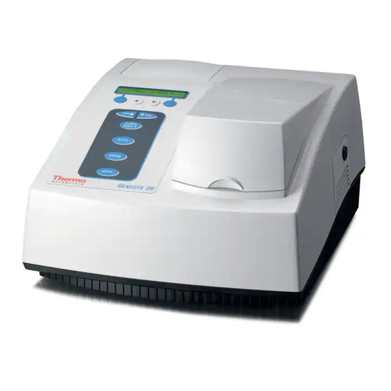
- Page 11 Section 1 Description The GENESYS™ 20 spectrophotometer is a bench-mount instrument that performs Absorbance, % Transmittance, and Concentration measurements within the wavelength range of 325 to 1100 nanometers. Its features include: Two-line, 20-character LCD display Tactile keyboard that clicks to indicate a key was pressed Optional cell holders available for a wide range of cuvettes, test tubes and longpath cells Optional internal printer...
- Page 12 Description Figure 4-1 - GENESYS 20 Components Figure 1.1 shows the main components of the instrument (indicated by the numerical call outs). These are as follows: On/Off switch (on back) LCD display Sample compartment door Keyboard Optional built-in printer Lamp compartment door...
- Page 13 Description Figure 4-2 - Keyboard Layout The main keyboard functions are shown in Figure 1.2 (indicated by the numerical call-outs). These are as follows: Display - 20-character, 2-line LCD Soft key 1 - Function varies depending on screen; generally Escape, Back Up, or Clear Soft key 2 - Function varies depending on screen;...
- Page 14 Description Utility - Accesses instrument set-up, diagnostics, and other functions Print - Sends currently displayed data to selected printer 1 - 4...
- Page 15 [30 cm W x 33 cm D x 19 cm H] Power requirements Selected automatically; 100 to 240 Volts, 50 to 60 Hz The GENESYS 20 spectrophotometer has been designed to operate under the environmental and electrical requirements listed below. Line voltages 100 - 240V ± 10% 50 - 60 Hz ±...
- Page 16 Specifications Storage environment F to 140 F [-40 C to 60 Relative humidity not to exceed 60%. Allow instrument to adjust to room temperature for 24 hours after taking it out of storage. Temperature should be maintained at ±4 F [±2 C ].
- Page 17 Section 3 Installation and Performance Checks The following performance checklist can be copied, completed, and a copy left with the end-user. The checklist should be used anytime an instrument is tested, or repaired. 3 - 1...
- Page 18 Installation and Performance Checks Thermo Spectronic Field Inspection / Performance Checklist GENESYS 20 Customer_______________________ Contact________________________ Phone #________________________ S/N____________________________ Cat #_____________ Man #_______ Date_______ SPECTRONIC Standards Kit, Certified Kit # ________________ Initial inspection - Appearance ..... . . Good___ Fair___ Poor___ Line voltage .
-
Page 19: Error Messages
A number of error messages are generated by the spectrophotometer to indicate improper operations. These are displayed for the operator (and explained in the Error Messages GENESYS 20 Operator's Manual) and can normally be resolved without further troubleshooting. They are included here for the convenience of the Service Technician. - Page 20 Troubleshooting Key not active Indicates a non-functional key was pressed. For example, this message would appear if [A/T/C] is pressed when viewing the Utility menu. The instrument beeps three times to announce the message, the message remains on the display for two seconds, then the normal display returns.
-
Page 21: General Troubleshooting Items
Troubleshooting General Troubleshooting Items Nothing Works (No lights, no fan) Check: Instrument is plugged in and there is power to the outlet. Line cord is good. Open fuse. This unit has two fuses. Both fuses must be good. Check for a defective power switch. Check primary power connection from switch to power supply. - Page 22 Troubleshooting Detector board. Check: +5vA at J1-1, or C7+ (Ground at J1-7 or C7-) at J1-2 Check output signal at J1-3. Should be -8v with room light on detector; 0v with detector dark. Mono Drive board. Check: +5v at J3-3, or C6+ (Ground at J3-5) +12v at J3-6 (Ground at J3-7) -12v at J3-8 (Ground at J3-7) +VMot at J3-1 (Ground at J3-2) (+VMot equals +5v)
- Page 23 Troubleshooting After the monochromator initializes, the unit goes to 546nm (or the user-designated power-on wavelength). An auto zero is performed at the current wavelength. Service Tools: H-152378 - Cuvette target H-152619 - Grating target H-152621 - Detector target The following tools are used on the production line and should NOT be used in the field: H-152620 - Turning mirror target tool H-152622 - Grating hold down fixture...
- Page 24 Common Problems and Probable Cause The following is a list of problems which may be encountered in servicing the GENESYS 20. The symptom is described in the left hand column. A suggested action is listed in the right hand column. Items in quotes ""...
- Page 25 Troubleshooting Check keyboard and display cables. Make sure they are properly plugged on (not offset by 1 pin). Hardware failure. Replace main board. Light not green at 550nm This is a gross wavelength error. The light beam in the sample compartment should be green at 550nm, red at 600nm, and blue at 450nm.
- Page 26 Troubleshooting Check lamp alignment. The lamp may not be aligned to the entrance slit. Turn the lamp adjustment cam 1/8 of a turn and power up again. Repeat this until lamp cam has been rotated for one full turn. Filter wheel, or detector board, or mono motor cable not connected to main board.
- Page 27 Troubleshooting "Invalid Wv Table" The stored wavelength calibration table has been lost. Replace it by using the wavelength table transfer program. The wavelength calibration information is available from the Rochester, NY facility. The table is identified by the instrument serial number. See section 8 below. EEPROM socket failure.
- Page 28 Troubleshooting The mono motor is defective. Do not replace mono motor. Replace instrument. "RAM Failure" The RAM is internal to the microprocessor. Therefore, either replace the 80C251 chip or the entire main board. Please note the second line of the display and return the chip to the factory.
- Page 29 Loss of memory on the internal EEPROM may have been caused by a loose EEPROM chip. SOLUTION: Before loading the Wavelength Calibration Tables into the GENESYS 20 instrument, please perform the following steps, which in some cases may remedy the problem: Ensure that the power is shut off and the ac power cord is disconnected from the rear of the GENESYS 20 instrument.
- Page 30 LOADING THE GENESYS 20 WAVELENGTH CALIBRATION TABLE Install the interface cable between the male 9 pin connector on the GENESYS 20 and the computer’s Com 1 port using a female 9 pin to female 9 pin straight cable ( 336042) or a female 9 to female 25 pin cable (336041).
- Page 31 The RS232 cable is connected to the Com 1 port on the computer. The RS232 setup on the GENESYS 20 is set up as detailed in step 3 above. If the file was loaded correctly, turn the instrument off and back on again. The wavelength tables should be loaded properly and the instrument should operate normally.
- Page 32 Troubleshooting 4 - 14...
-
Page 33: Lamp Replacement
Section 5 Routine Maintenance NOTE To clean the instrument, gently wipe the outside of the instrument with a soft cloth to remove any dust or spills. Water, isopropyl alcohol and other common laboratory cleaning agents may be used if necessary. WARNING HIGH VOLTAGES EXIST INSIDE THE CABINET ANY TIME THE POWER CORD IS PLUGGED INTO A LIVE RECEPTACLE, AND THE... - Page 34 Routine Maintenance Use a coin or large screwdriver to loosen the quarter-turn fastener on the door of the lamp compartment. Pull up on the door and lift to remove it. Figure 5.1 - Lamp Compartment Loosen and remove the thumbscrew (refer to Figure 5.1, [Item #1]). Carefully pull the tab at the top of the lamp holder assembly [Item #2] to lift the assembly out of the instrument.
- Page 35 Press [Esc] twice to return to the standard display. If desired, reset the hours of lamp operation to zero (refer to the GENESYS 20 Operator's Manual). Replace the door of the lamp compartment and allow the lamp to warm up for at least 30 minutes.
-
Page 36: Replace Fuse
Routine Maintenance NOTE Replace Fuse The instrument fuse must be replaced with the same type and rating fuse. Use IEC standard 5x20mm, Type F fuse, 2.5A, 250VAC, 1500A interrupt rating [Littlefuse #216025]. NOTE The fuse is located in the power entry module on the back of the instrument. - Page 37 Routine Maintenance Use the screwdriver to remove the fuse holder to access the fuses as shown in Figure 5.3. Unsnap both fuses to remove them (refer to Figure 5.3, [Item #1]). Insert the new fuses, pushing them in so they snap into place.
- Page 38 Routine Maintenance 5 - 6...
- Page 39 Section 6 Optical Description The monochrometer configuration in the GENESYS 20 uses a modified single mirror Czerny-Turner mounting technique. A schematic of the monochromator layout is shown in Figure 6.1. Figure 6.1 - Optical Path Lamp: The Tungsten-Halogen lamp provides continuous energy output.
- Page 40 Optical Description Lens: The lens brings the beam leaving the exit slit to a focus at the center of the sample location. Detector: The light is transmitted through the sample and lands on the detector. The detector is angled to prevent light reflection back into the sample compartment area.
- Page 41 Section 7 Optical Alignment WARNING HIGH VOLTAGES EXIST INSIDE THE CABINET ANY TIME THE POWER CORD IS PLUGGED INTO A LIVE RECEPTACLE, AND THE POWER SWITCH IS TURNED ON. THE POWER SWITCH SHOULD ALWAYS BE TURNED OFF AND THE LINE CORD UNPLUGGED FROM THE RECEPTACLE BEFORE ACCESSING THE INTERIOR OF THE SPECTROPHOTOMETER.
-
Page 42: Filter And Lens Assembly Alignment
THE HOLE. THIS WILL IMPAIR THE ABILITY OF THE SCREW TO PROPERLY SECURE THE ASSEMBLY. Most of the optical components of the GENESYS 20 Spectrophotometer are fixed at the factory and are not field adjustable. The filter and lens assembly is Filter And Lens the one component which may require field alignment. -
Page 43: Alignment Procedure
Optical Alignment Replace the cover assembly (refer to "Section 9 - Disassembly and Replacement"). Open the sample cover door and leave open through the procedure. Place the alignment tool in the sample holder so the vertical alignment line is facing the filter and lens assembly. Insert the power cord and turn on power to the assembly. - Page 44 Optical Alignment WARNING THE FILTER WHEEL ALIGNMENT PROCEDURE REQUIRES THE OPERATOR TO HAVE POWER TURNED ON WHILE ACCESSING THE INTERIOR OF THE CABINET. THEREFORE, IT IS VERY IMPORTANT THAT ONLY TRAINED TECHNICIANS, AWARE OF THE DANGERS AND PROPER SAFETY PRECAUTIONS, PERFORM THIS ALIGNMENT PROCEDURE.
-
Page 45: Primary Wiring
Section 8 Electrical Circuit Description and Adjustment NOTE Refer to "Section 12 - Drawings and Schematics" for the layout and schematic drawings of all boards referenced in this section. AC power is provided through a detachable power cable to a dual-fused power entry module (4001-652) which contains a single-throw double-pole power Primary Wiring switch. -
Page 46: Universal Input Ac/Dc Switching Power Supply Board
Electrical Circuit Description and Adjustment The AC/DC power supply provides fixed +5 volt and -12 volt supplies and a quasi-regulated +12 volt supply. Heavy loading on the +5 volt supply will cause Universal Input the +12 volt supply to decrease in magnitude by as much as 2 volts. Short AC/DC Switching circuit, overload, and over temperature protection is built-in. -
Page 47: Main Board
Electrical Circuit Description and Adjustment Main Board 4001-6044, Revision B 8.3.1 The Microcontroller Digital Circuitry An Intel 80C251 8-Bit Microcontroller is used to control all instrument functions and to process data into the appropriate units. The 80C251 contains a central processing unit, a clock generator using an external 11.0592 MHz crystal, a power-on reset circuit (with U12 providing the control signal), a serial port, timers for control of the A/D converter and miscellaneous functions, and I/O... -
Page 48: Analog Circuitry
Electrical Circuit Description and Adjustment Direct I/O Signals A number of direct I/O signals, located on the Microcontroller ports 1 and 3, are used for timing-critical controls. Devices controlled include the serial port, display, printer, write control, address bits, and the grating motor limit switch. 8.3.2 Gain-Controlled Amplifier Analog Circuitry... - Page 49 Electrical Circuit Description and Adjustment op-amp offset voltage. The comparator function is returned to U41 by setting /ZERO HIGH and the next signal to be measured is selected. The MEASURE signal is then set HIGH to start the capacitor discharge and enable the output latch.
- Page 50 Electrical Circuit Description and Adjustment Filter Wheel Drive The filter wheel stepper motor is driven by open-collector transistors in U37. When moving the 12 volt unipolar stepper motor, Q2 is turned on to drive the motor with 12 volts. Once the motor is at rest, Q2 is turned off and the motor is held by 4.3 volts through D18 to reduce power consumption.
-
Page 51: Mono Drive Board
Electrical Circuit Description and Adjustment Low-pass filtering has been applied to the ±12 volt power supplies. A 5.00 volt precision voltage reference (U6) is used for the D/A converters. The Mono Drive Board monochromator wavelength is controlled with a unipolar stepper motor. 4001-6054, Microstepping is employed with 16 microsteps per whole step resolution to Revision B... -
Page 52: Detector Board
Electrical Circuit Description and Adjustment Detector Board 4001-6034, Revision A CAUTION THE DETECTOR BOARD IS EXTREMELY SENSITIVE TO SURFACE CONTAMINATION AND SHOULD ONLY BE HANDLED BY THE EDGES. The Detector Board contains a transimpedance (I to v) preamplifier with a “T- gain”... - Page 53 Section 9 Disassembly and Replacement WARNING HIGH VOLTAGES EXIST INSIDE THE CABINET ANY TIME THE POWER CORD IS PLUGGED INTO A LIVE RECEPTACLE, AND THE POWER SWITCH IS TURNED ON. ALWAYS TURN OFF THE POWER SWITCH AND UNPLUG THE LINE CORD FROM THE RECEPTACLE BEFORE ACCESSING INTERIOR...
-
Page 54: External Covers
Disassembly and Replacement Turn off power to the GENESYS 20 using the ON/OFF switch at the back of the unit. External Covers Unplug the power cord from the receptacle and remove the power cord from its connector at the back of the main housing cover. -
Page 55: Printer Cover
Dissassembly and Replacement 9.1.2 The printer cover is located at the Printer Cover back left corner on the top of the cover assembly. This may be a blank cover or may include an integral printer (optional). It can be removed separately to gain access to the printer or EPROMs on the main circuit board or can be left in place... - Page 56 Disassembly and Replacement Reach under the front of the unit and press the two clips toward the sides of the unit and up. Figure 9.3 shows a bottom view of the base assembly indicating the location of the two clips. Figure 9.3 - Base Assembly: Bottom View CAUTION WHEN LIFTING THE COVER ASSEMBLY, TAKE CARE NOT TO...
- Page 57 Dissassembly and Replacement CAUTION WHEN REMOVING CONNECTORS FROM THE CIRCUIT BOARD RECEPTACLES, ALWAYS GRASP BODY CONNECTOR — NEVER PULL ON THE WIRE HARNESS. FAILURE TO OBSERVE THIS CAUTION MAY RESULT IN DAMAGE TO THE WIRING HARNESS. Set the cover assembly on its side and carefully disconnect the key pad and display cables from the main circuit board (refer to Figure 9.4, 9.7).
-
Page 58: Sample Compartment Cover Assembly
Disassembly and Replacement While lowering the cover, make sure the cover assembly slots are behind the attachment screws on the back of the base assembly. Rotate the cover assembly and rear panel forward until the connectors on the main board are in their proper positions. Make sure no wires are caught between the cover assembly and base assembly. - Page 59 Dissassembly and Replacement Remove the sample compartment cover from the sample compartment hinge. Using a very small screwdriver, gently pry up on the center of each hinge tab while gently pulling the cover slightly away from the hinge. Slide the cover off the hinge tabs. Remove the hinge assembly from the main cover assembly.
-
Page 60: Rear Panel
Disassembly and Replacement 9.1.5 REMOVAL Rear Panel Remove the main cover assembly (refer to "Section 9.1.3 - Cover Assembly"). Completely remove the two screws at the back of the base assembly previously loosened to remove the cover assembly. Move the top of the panel away from the main circuit board until the board is out of its mounting slot and the panel is clear of the connectors on the back edge of the board. -
Page 61: Front Panel Assemblies
Dissassembly and Replacement The key pad or display each have a wire harness connected to the main circuit board. Therefore, the cover assembly must be removed including disconnecting Front Panel these cables before either the key pad or display can be changed. Assemblies 9.2.1 REMOVAL... - Page 62 Disassembly and Replacement Make sure the display is clean of all dust and finger prints. Also check the back side of the display cover screen in the key pad to make sure it is clean. Orient the key pad and start the wire harness through the hole in the cover assembly.
-
Page 63: Internal Assemblies
Dissassembly and Replacement INTERNAL ASSEMBLIES 9.3.1 NOTE Main Circuit Board The EPROM and EEPROM can be accessed by removing only the printer cover. However, it may be easier to replace these with the cover assembly removed so there is full access to the circuit board. Remove the main cover assembly (refer to "Section 9.1.3 - Cover Assembly"). - Page 64 Disassembly and Replacement Remove the two screws at the front of the circuit board securing the circuit board to the base assembly. NOTE The screws securing the circuit board also secure the monochromator cover. Carefully lift the circuit board off the base assembly. REPLACEMENT The EEPROM contains the calibration constants for the monochromator and other instrument parameters.
-
Page 65: Power Entry Module
Dissassembly and Replacement Note the location of Pin 1. Using a ROM puller, remove the EEPROM from the board. Pull up equally to prevent bending any of the pins. NOTE When replacing the EEPROM in the new circuit board, note that the socket has four more holes than the EEPROM has pins. - Page 66 Disassembly and Replacement Figure 9.9 - Interior Layout Remove the rear panel (refer to "Section 9.1.5 - Rear Panel"). NOTE It is sometimes easier to lift the module out of its cutout (Step 6) before the wires are removed to make it easier to grasp the connectors with pliers.
-
Page 67: Power Supply
Dissassembly and Replacement Remove the two power connector wires (white wires) from the upper and lower terminals on the right side (as viewed from the rear). Lift the power entry module out of its cutout in the base assembly. REPLACEMENT NOTE If desired, the wires can be attached to the terminals on the new power module before the module is to be replaced. - Page 68 Disassembly and Replacement Disconnect the connector for the wire harness to the power entry module from the socket on the power supply (refer to Figure 9.9). Disconnect the ground wire connector (green and yellow wire) from the power supply. Remove the four thread-forming screws which secure the power supply to the base assembly.
-
Page 69: Detector Assembly
Dissassembly and Replacement Remove the main cover assembly (refer to "Section 9.1.3 - Cover Assembly"). CAUTION DO NOT TOUCH THE DETECTOR. HOLD THE DETECTOR ASSEMBLY AT THE SIDES OR TOP AND BOTTOM ONLY. DO NOT REACH BEHIND THE ASSEMBLY. FAILURE TO OBSERVE THIS CAUTION MAY RESULT IN LOSS OF ACCURACY AND PERFORMANCE. -
Page 70: Lamp Socket
Disassembly and Replacement REPLACEMENT Slide the entrance slit/illumination assembly into position. Replace the two screws on top of the assembly. DO NOT OVER TIGHTEN! Replace the monochromator cover making sure the filter wheel motor cable is properly positioned. Replace the main circuit board (refer to "Section 9.3.1 - Main Circuit Board"). -
Page 71: Spring
Dissassembly and Replacement Unscrew the lamp holding knob (turn counterclockwise). Remove the socket from the assembly. REPLACEMENT Position the socket on the entrance slit/illumination assembly mounting screw. Make sure the screw is properly positioned and not bent or squeezed. Screw the lamp holding knob onto the mounting screw (turn clockwise). Connect the lamp cable to the main circuit board. -
Page 72: Filter And Lens Assembly
Disassembly and Replacement 9.3.6 REMOVAL Filter and Lens Assembly Remove the main cover assembly (refer to "Section 9.1.3 - Cover Assembly"). Remove the main circuit board (refer to "Section 9.3.1 - Main Circuit Board"). Lift off the monochromator cover. CAUTION DO NOT TOUCH THE LENS ON THE BACK SIDE OF THE FILTER WHEEL ASSEMBLY OR ANY OF THE FILTER ELEMENTS. -
Page 73: Filter Wheel
Dissassembly and Replacement 9.3.6.1 Filter Wheel Figure 9.11 - Filter and Lens Assembly REMOVAL Remove the filter and lens assembly from the base assembly (refer to "Section 9.3.6 - Filter Wheel Assembly"). Remove the retaining ring securing the filter wheel and discard. This retaining ring will not be reused. -
Page 74: Filter Wheel Motor
Disassembly and Replacement Clamp the Teflon washer and filter wheel in position using a new retaining ring. Replace the filter and lens assembly in the base assembly (refer to "Section 9.3.6 - Filter and Lens Assembly"). 9.3.6.2 REMOVAL Filter Wheel Motor Remove the filter and lens assembly from the base assembly (refer to "Section 9.3.6 - Filter Wheel Assembly"). - Page 75 Dissassembly and Replacement Turn the instrument over and lay it on its top. Figure 9.12 - Genesys 20: Bottom View Remove the Sector gear and Limit Switch Cover. Remove the two screws which secure the limit switch. Remove the two wires attached to the limit switch terminals.
-
Page 76: Limit Switch
Disassembly and Replacement Replace the two screws. Replace the two screws which secure the limit switch. Turn the unit back over to its upright position. 9 - 24... - Page 77 20-Column Internal Printer (user-installable); includes 5 rolls of paper 333150 SPECTRONIC Standards 336041 Interface cable to connect GENESYS 20 Series to IBM PC/XT computer 335942 Interface cable to connect GENESYS 20 Series to IBM/AT computer 336043 Interface cable to connect GENESYS 20 Series to non-IBM equipment...
- Page 78 Accessories 10 - 2...
- Page 79 Cable, GENESYS 20 Limit Switch (SPS) 4001-262 Power Entry Cable Assembly (SPS) 4001-263 Filter Wheel, GENESYS 20 (SPS) 4001-264 Filter Wheel, GENESYS 20 with Lens and Motor 4001-265 Turning Mirror Assembly (SPS) 4001-266 Grating Assembly (SPS) 4001-267 Knob ASM, GENESYS 20 Lamp (SPS)
- Page 80 Spare Parts and Special Tools Service Tools H152378 - Cuvette target H152619 - Grating target H152621 - Detector target H152626 - Filter motor pinion spacer The following tools are used on the production line and should not be used in the field (list provided as reference only): H152620 - Turning mirror target tool H152622 - Grating hold down fixture...
- Page 81 Section 12 Drawings and Schematics This section provides interconnect, assembly, schematic drawings and parts lists for the mechanical, electrical, and cable assemblies of the GENESYS 20 Spectrophotometer. 12.1 NOTE Mechanical All the mechanical assemblies are on different sheets of Thermo Assemblies Spectronic Drawing Number 4001-200 —...
- Page 82 Drawings and Schematics FIG. ASSEMBLY DESCRIPTION PART NO. REV. SHTS. 12-27 Interface Cable - IBM PC/AT 336042-000 12-28 Interface Cable - Non-IBM 226043-000 BOARDS AND SCHEMATICS (See Section 12-2): 12-29 Main Board Assembly 4001-6024 12-30 Detector Board Assembly 4001-6034 12-31 Main Board Assembly 4001-6044 12-32...
- Page 83 Drawings and Schematics FIG. ASSEMBLY DESCRIPTION PART NO. REV. SHTS. ACCESSORIES 12-65 Printer/Relay Cable 4001-1601 12-66 Printer Cable 4001-1604 12-67 Printer Assembly 4001-200 12 - 3...
- Page 84 Drawings and Schematics Figure 12.1 -Lamp Socket Assembly [4001-250, Rev. E] Figure 12.2 - Filter Motor Assembly [336001-671, Rev. E] 12 - 4...
- Page 85 Drawings and Schematics Figure 12.3 - Grating Motor Assembly [4001-251, Rev. E] Figure 12.4 - Fan Assembly [4001-252, Rev. C] (See Update Information section of manual) 12 - 5...
- Page 86 Drawings and Schematics Figure 12.5 - Mono Motor Power Cable Assembly [4001-253, Rev. E] 12 - 6...
- Page 87 Drawings and Schematics Figure 12.6 - Mono Motor Control Cable Assembly [4001-254, Rev. E] Figure 12.7 - Detector Cable Assembly [4001-255, Rev. E] 12 - 7...
- Page 88 Drawings and Schematics Figure 12.8 - Power Supply Cable Assembly [4001-256, Rev. E] 12 - 8...
- Page 89 Drawings and Schematics Figure 12.9 - Limit Switch Cable Assembly [4001-261, Rev. E] 12 - 9...
- Page 90 Drawings and Schematics Figure 12.10 - Power Entry Cable Assembly [4001-262, Rev. E] Figure 12.11 - Filter Assembly [4001-263, Rev. E] 12 - 10...
- Page 91 Drawings and Schematics Figure 12.12 - Filter & Lens Assembly [4001-264, Rev. G] 12 - 11...
- Page 92 Drawings and Schematics Figure 12.13 - Turning Mirror Assembly [4001-265, Rev. E] 12 - 12...
- Page 93 Drawings and Schematics Figure 12.14 - Grating & Mount Assembly [4001-266, Rev. E] 12 - 13...
- Page 94 Drawings and Schematics Figure 12.15 - Cuvette Adapter Assembly [4010-000, Rev. E] Figure 12.16 - Lamp Knob Assembly [4001-267, Rev. E] 12 - 14...
- Page 95 Drawings and Schematics Figure 12.17 - Entrance Slit / Illumination Assembly [4001-268, Rev. E] 12 - 15...
- Page 96 Drawings and Schematics Figure 12.18 - Display Assembly [4001-269, Rev. E] 12 - 16...
- Page 97 Drawings and Schematics Figure 12.19 - Detector Assembly [4001-270, Rev. E] 12 - 17...
- Page 98 Drawings and Schematics Figure 12.20 - Main Cover Assembly [4001-271, Rev. D] 12 - 18...
- Page 99 Drawings and Schematics Figure 12.21 - Lamp Door Assembly [4001-272, Rev. D] 12 - 19...
- Page 100 Drawings and Schematics Figure 12.22 - Main Board [4001-6046, Rev. K] Figure 12.23 - Mono Motor Board [4001-6056, Rev. K] 12 - 20...
- Page 101 Drawings and Schematics Figure 12.26 - Interface Cable - IBM PC/XT [336041-1602, Sht. 1,Rev. A] 12 - 25...
- Page 102 Drawings and Schematics Figure 12.27 - Interface Cable - IBM PC/AT [335942-000, Sht. 1, Rev. A] 12 - 26...
- Page 103 Drawings and Schematics Figure 12.28 - Interface Cable - Non-IBM [336043-000, Sht. 1, Rev. A] 12 - 27...
- Page 104 Drawings and Schematics 12 - 28...
- Page 105 Drawings and Schematics 12.2 Boards and Schematics Main Board Assembly [4001-6024, Rev. A] Ref. Des. Description Main Board Heatsink, Thermalloy #6043PB Not Presently Used Beeper Capacitor Cerm., .1 Mfd 50V Capacitor Tant., 4.7 Mfd 10V Capacitor Tant., 10 Mfd 20V S/A C1 .1 Mfd 50V Cerm.
- Page 106 Drawings and Schematics Ref. Des. Description S/A C1 .1 Mfd 50V Cerm. S/A C1 .1 Mfd 50V Cerm. S/A C1 .1 Mfd 50V Cerm. S/A C1 .1 Mfd 50V Cerm. Capacitor Polycarb., .1 Mfd 100V Capacitor Cerm., .022 Mfd 50V Capacitor Polyprop., .1 Mfd 100V S/A C1 .1 Mfd 50V Cerm.
- Page 107 Drawings and Schematics Ref. Des. Description Wafer, Non-Polarized 12 Pin KK100, Molex #22-03-2121 Wafer, Right Angle Polarized 2 Pin KK156, Molex #26-48-1024 Wafer, Right Angle Polarized 8 Pin KK156, Molex #26-48-1084 Wafer, Right Angle Polarized 7 Pin KK100, Molex #22-05-3071 Wafer, Right Angle Polarized 2 Pin KK100, Molex #22-05-3021 Wafer, Right Angle Polarized 8 Pin...
- Page 108 Drawings and Schematics Ref. Des. Description S/A R17 634.0 K 1% 1/4W MF S/A R19 4.99 K 1% 1/4W MF S/A R18 10.0 K 1% 1/4W MF Resistor MF, 1.00 K 1% 1/4W Resistor MF, 49.9 K 1% 1/4W S/A R4 10 K 5% 1/4W CF S/A R25 1.00 K 1% 1/4W MF Resistor MF, 2.49 K 1% 1/4W S/A R17 634.0 K 1% 1/4W MF...
- Page 109 Drawings and Schematics Ref. Des. Description IC TL071CP IC LM78L05 IC LM337T IC LM78L08 IC CD4051 IC 74HC132 S/A U17 74HC273 S/A U17 74HC273 S/A U17 74HC273 S/A U17 74HC273 IC ULN2803 S/A U13 74HC08 S/A U37 ULN2803 IC TLC2272CP IC TL072P IC MC1404U5 (REF 02) IC CD4053 (MC14053)
- Page 110 Drawings and Schematics Ref. Des. Description Resistor Netwk, Com., 10 K SIP (9) S/A Z4 10 K SIP Netwk S/A Z2 470 Ohm DIP Netwk S/A Z2 470 Ohm DIP Netwk S/A Z4 10 K SIP Netwk Resistor Netwk, Precision, 1.0K/9.0K 12 - 34...
- Page 111 Drawings and Schematics Main Board Assembly [4001-6044, Rev. B] Ref. Des. Description Main Board Heatsink, Thermalloy #6043PB Not Presently Used Beeper Capacitor Cerm., .1 Mfd 50V Capacitor Tant., 4.7 Mfd 10V Not Presently Used S/A C1 .1 Mfd 50V Cerm. S/A C1 .1 Mfd 50V Cerm.
- Page 112 Drawings and Schematics Ref. Des. Description Capacitor Polycarb, .1 Mfd 100V Not Presently Used Capacitor Polyprop., .1 Mfd 100V S/A C1 .1 Mfd 50V Cerm. S/A C1 .1 Mfd 50V Cerm. S/A C1 .1 Mfd 50V Cerm. S/A C1 .1 Mfd 50V Cerm. S/A C22 10 Mfd 20V Tant.
- Page 113 Drawings and Schematics Ref. Des. Description Wafer, Right Angle Polarized 8 Pin KK156, Molex #26-48-1084 Wafer, Right Angle Polarized 7 Pin KK100, Molex #22-05-3071 Wafer, Right Angle Polarized 2 Pin KK100, Molex #22-05-3021 Wafer, Right Angle Polarized 8 Pin KK100, Molex #22-05-3081 Wafer, Polarized 3 Pin KK100, Molex #22-23-2031 Not Presently Used...
- Page 114 Drawings and Schematics Ref. Des. Description S/A R4 10 K 5% 1/4W CF S/A R17 634.0 K 1% 1/4W MF S/A R19 4.99 K 1% 1/4W MF S/A R18 10.0 K 1% 1/4W MF Resistor MF, 1.00 K 1% 1/4W S/A R10 49.9 K 1% 1/4W MF S/A R4 10 K 5% 1/4W CF S/A R25 1.00 K 1% 1/4W MF...
- Page 115 Drawings and Schematics Ref. Des. Description IC 74HC04 IC 74HC139 IC 74HC154N IC MC34166T IC TL071CP IC LM78L05 IC LM337T IC LM78L08 IC CD4051 IC 74HC132 S/A U17 74HC273 S/A U17 74HC273 S/A U17 74HC273 S/A U17 74HC273 IC ULN2803 IC TLC2272ACP IC TL072P IC MC1404U5 (REF 02)
- Page 116 Drawings and Schematics Ref. Des. Description S/A Z2 470 Ohm DIP Netwk Resistor Netwk, Com., 10 K SIP (9) S/A Z4 10 K SIP Netwk S/A Z2 470 Ohm DIP Netwk S/A Z2 470 Ohm DIP Netwk S/A Z4 10 K SIP Netwk Resistor Netwk, Precision, 1.0K/9.0K 12 - 44...
- Page 117 Drawings and Schematics Mono Driver Board Assembly [4001-6054, Rev. A] Ref. Des. Description Mono Driver Board Heatsink, Thermalloy #6099B Insulator Shoulder Washer Screw, 4-40T x .50 Long Pan Head Keps Nut, #4-40T Capacitor Cerm, .1 MFD 50V Capacitor Cerm, .01 MFD 80V S/A C1 .1 Mfd 50V Cerm.
- Page 118 Drawings and Schematics Ref. Des. Description S/A Q1 MTP3055E S/A Q1 MTP3055E Resistor MF, 10.0 K 1% 1/4W S/A R1 10.0 K 1% 1/4W MF Resistor MF, 20.0 K 1% 1/4W S/A R3 20.0 K 1% 1/4W MF Resistor CF, 1 K 5% 1/4W Resistor MF, 1.50 K 1% 1/4W Resistor Power, 0.47 Ohm 5% 1/2W S/A R5 1K 5% 1/4W CF...
- Page 119 Drawings and Schematics Figure 12.29 Printer/Relay Cable 12 - 115...
- Page 120 Drawings and Schematics Figure 12.30 Printer Cable 12 - 116...
- Page 121 Drawings and Schematics Figure 12.31 Printer Assembly 12 - 117...
- Page 122 Drawings and Schematics 12 - 118...
- Page 123 Drawings and Schematics Figure 12.24 Base Assembly [4001-200, Sht. 7, Rev. C] 12 - 21...
- Page 124 Drawings and Schematics 12 - 22...
- Page 125 Drawings and Schematics Figure 12.25 Main Assembly [4001-200, Sht. 8, Rev. C] 12 - 23...
- Page 126 Drawings and Schematics 12 - 24...
- Page 127 Drawings and Schematics Figure 12.29 Main Board Assembly [4001-6024, Rev. A] 12 - 35...
- Page 128 Drawings and Schematics 12 - 36...
- Page 129 Drawings and Schematics Detector Board Assembly [4001-6034, Rev. B] Ref. Des. Description Detector Board Pin Socket Capacitor Cerm., .1 Mfd 50V S/A C1 .1 Mfd 50V Cerm. Capacitor Polycarb., 2200 Pf 50V S/A C3 2200 Pf 50V Polycarb. S/A C1 .1 Mfd 50V Cerm. S/A C1 .1 Mfd 50V Cerm.
- Page 130 Drawings and Schematics 12 - 38...
- Page 131 Drawings and Schematics Figure 12.31 Main Board Assembly [4001-6044, Rev. B] 12 - 45...
- Page 132 Drawings and Schematics 12 - 46...
- Page 133 Drawings and Schematics Figure 12.32 Mono Driver Board Assembly [4001-6054, Rev. A] 12 - 49...
- Page 134 Drawings and Schematics 12 - 50...
- Page 135 Drawings and Schematics Figure 12.33 Primary Wiring Schematic [4001-600, Rev. B] 12 - 51...
- Page 136 Drawings and Schematics 12 - 52...
- Page 137 Drawings and Schematics Figure 12.34 Detector (Preamp) Board Schematic [4001-6031, Rev. B] 12 - 53...
- Page 138 Drawings and Schematics 12 - 54...
- Page 139 Drawings and Schematics Figure 12.35 Mono Drive Board Schematic [4001-605-1, Sht. 1] 12 - 55...
- Page 140 Drawings and Schematics 12 - 56...
- Page 141 Drawings and Schematics Figure 12.36 Mono Drive Board Schematic [4001-605-1, Sht. 2] 12 - 57...
- Page 142 Drawings and Schematics 12 - 58...
- Page 143 Drawings and Schematics Figure 12.37 Processor Schematic [4001-6021, Sht. 1, Rev. A] 12 - 59...
- Page 144 Drawings and Schematics 12 - 60...
- Page 145 Drawings and Schematics Figure 12.38 Memory 1 /I /O Decode Schematic [4001-6021, Sht. 2, Rev. A] 12 - 61...
- Page 146 Drawings and Schematics 12 - 62...
- Page 147 Drawings and Schematics Figure 12.39 Memory 2 - Oem / Optional Schematic [4001-6021, Sht. 3, Rev. A] 12 - 63...
- Page 148 Drawings and Schematics 12 - 64...
- Page 149 Drawings and Schematics Figure 12.40 Keyboard & Display Control Schematic [4001-6021, Sht. 4, Rev. A] 12 - 65...
- Page 150 Drawings and Schematics 12 - 66...
- Page 151 Drawings and Schematics Figure 12.41 Mono Drive & Analog Gain Reg. Schematic [4001-6021, Sht. 5, Rev. A] 12 - 67...
- Page 152 Drawings and Schematics 12 - 68...
- Page 153 Drawings and Schematics Figure 12.42 Filter Wheel and T-O-Y / Lamp Control Schematic [4001-6021, Sht. 6, Rev. A] 12 - 69...
- Page 154 Drawings and Schematics 12 - 70...
- Page 155 Drawings and Schematics Figure 12.43 Analog Processing Schematic [4001-6021, Sht. 7, Rev. A] 12 - 71...
- Page 156 Drawings and Schematics 12 - 72...
- Page 157 Drawings and Schematics Figure 12.44 A / D Schematic [4001-6021, Sht. 8, Rev. A] 12 - 73...
- Page 158 Drawings and Schematics 12 - 74...
- Page 159 Drawings and Schematics Figure 12.45 Lamp Power Supply Schematic [4001-6021, Sht. 9, Rev. A] 12 - 75...
- Page 160 Drawings and Schematics 12 - 76...
- Page 161 Drawings and Schematics Figure 12.46 Internal Printer Interface Schematic [4001-6021, Sht. 10, Rev. A] 12 - 77...
- Page 162 Drawings and Schematics 12 - 78...
- Page 163 Drawings and Schematics Figure 12.47 External Printer Interface Schematic [4001-6021, Sht. 11, Rev. A] 12 - 79...
- Page 164 Drawings and Schematics 12 - 80...
- Page 165 Drawings and Schematics Figure 12.48 RS-232 Interface Schematic [4001-6021, Sht. 12, Rev. A] 12 - 81...
- Page 166 Drawings and Schematics 12 - 82...
- Page 167 Drawings and Schematics Figure 12.49 Accessory Module Interface Schematic [4001-6021, Sht. 13, Rev. A] 12 - 83...
- Page 168 Drawings and Schematics 12 - 84...
- Page 169 Drawings and Schematics Figure 12.50 Board Power Supply Schematic [4001-6021, Sht. 14, Rev. A] 12 - 85...
- Page 170 Drawings and Schematics 12 - 86...
- Page 171 Drawings and Schematics Figure 12.51 Processor Schematic [4001-6041, Sht. 1, Rev. D] 12 - 87...
- Page 172 Drawings and Schematics 12 - 88...
- Page 173 Drawings and Schematics Figure 12.52 Memory 1 / I / O Decode Schematic [4001-6041, Sht. 2, Rev. D] 12 - 89...
- Page 174 Drawings and Schematics 12 - 90...
- Page 175 Drawings and Schematics Figure 12.53 Memory 2 - Oem / Optional Schematic [4001-6041, Sht. 3, Rev. D] 12 - 91...
- Page 176 Drawings and Schematics 12 - 92...
- Page 177 Drawings and Schematics Figure 12.54 Keyboard & Display Control Schematic [4001-6041, Sht. 4, Rev. D] 12 - 93...
- Page 178 Drawings and Schematics 12 - 94...
- Page 179 Drawings and Schematics Figure 12.55 Mono Drive & Analog Gain Reg. Schematic [4001-6041, Sht. 5, Rev. D] 12 - 95...
- Page 180 Drawings and Schematics 12 - 96...
- Page 181 Drawings and Schematics Figure 12.56 Filter Wheel and T-O-Y / Lamp Control Schematic [4001-6041, Sht. 6, Rev. D] 12 - 97...
- Page 182 Drawings and Schematics 12 - 98...
- Page 183 Drawings and Schematics Figure 12.57 Analog Processing Schematic [4001-6041, Sht. 7, Rev. D] 12 - 99...
- Page 184 Drawings and Schematics 12 - 100...
- Page 185 Drawings and Schematics Figure 12.58 A / D Schematic [4001-6041, Sht. 8, Rev. D] 12 - 101...
- Page 186 Drawings and Schematics 12 - 102...
- Page 187 Drawings and Schematics Figure 12.59 Lamp Power Supply Schematic [4001-6041, Sht. 9, Rev. D] 12 - 103...
- Page 188 Drawings and Schematics 12 - 104...
- Page 189 Drawings and Schematics Figure 12.60 Internal Printer Interface [4001-6041, Sht. 10, Rev. D] 12 - 105...
- Page 190 Drawings and Schematics 12 - 106...
- Page 191 Drawings and Schematics Figure 12.61 External Printer Interface [4001-6041, Sht. 11, Rev. D] 12 - 107...
- Page 192 Drawings and Schematics 12 - 108...
- Page 193 Drawings and Schematics Figure 12.62 RS-232 Interface Schematic [4001-6041, Sht. 12, Rev. D] 12 - 109...
- Page 194 Drawings and Schematics 12 - 110...
- Page 195 Drawings and Schematics Figure 12.63 Accessory Module Interface Schematic [4001-6041, Sht. 13, Rev. D] 12 - 111...
- Page 196 Drawings and Schematics 12 - 112...
- Page 197 Drawings and Schematics Figure 12.64 Power Supply Board Schematic [4001-6041, Sht. 14, Rev. D] 12 - 113...
- Page 198 Drawings and Schematics 12 - 114...
- Page 199 Section 13 Update Information Fan and Fan Guard Part Change Problem: Fails Electronic Discharge (ESD) Test. This test is required as part of CE approval. Note - The instrument properly meets photometric performance specifications with the original fan motor/fan guard. Symptom/Cause: System lockups during ESD performance testing.
- Page 200 Update Information “Sample Too Bright” Error Message Problem: At turn on or during operation the error message “Sample too bright” appears on the screen. At this point, the system locks up. Symptom/Cause: Can be caused by the instrument operator by opening the sample compartment door during a measurement.
- Page 201 When replacing the 4001-6046 Main PCB, remove the EEPROM from the old board and install it into the new board. The current (since 01 Feb 1999) 4001-6046 boards are shipped without a 335110-661 EEPROM. Produce Affected: All GENESYS 20 models 13-3...
- Page 202 Update Information Change in Lamp Eccentric The 4001-115 Lamp Eccentric (also called the ‘alignment screw’) is used to align the lamp in the GENESYS 20 spectrophotometer. This item has been changed as follows: The lamp eccentric used to be adjusted by using a Phillips-head screwdriver to maximize the lamp energy throughput.
- Page 203 THERMO SPECTRONIC (North America) 820 Linden Avenue, Rochester, NY 14625, USA Telephone: (800) 654-9955 or (585) 248-4000 Fax: (585) 248-4200 E-Mail: info@thermospectronic.com Web Site: www.thermospectronic.com THERMO SPECTRONIC (Europe) Mercers Row, Cambridge CB5 8HY, UK Telephone: Int +44 (0) 1223 446655 Fax: Int +44 (0) 1223 446644 E-Mail: info@thermospectronic.co.uk...
- Page 204 GENESYS™ 20 Service Spectrophotometer Manual...
- Page 205 Artisan Technology Group is your source for quality new and certified-used/pre-owned equipment SERVICE CENTER REPAIRS WE BUY USED EQUIPMENT • FAST SHIPPING AND DELIVERY Experienced engineers and technicians on staff Sell your excess, underutilized, and idle used equipment at our full-service, in-house repair center We also offer credit for buy-backs and trade-ins •...
Need help?
Do you have a question about the GENESYS 20 and is the answer not in the manual?
Questions and answers