Table of Contents
Advertisement
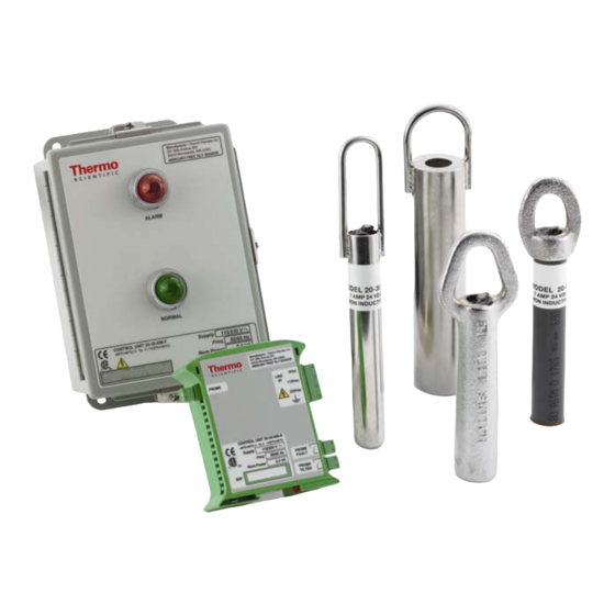
RAMSEY MERCURY FREE TILT SENSORS
FOR NON-HAZARDOUS AREAS
CONTROL UNITS
Model 20-35-NM-F
Model 20-35-NM-DIN
Manufacturer:
Thermo Fisher Scientific
th
501 90
Avenue NW
55433 Minneapolis, MN (USA)
(800) 445-3503
Mercury Free Tilt Sensor
User's Guide
REC 4274 Rev. C
PROBES
Model 20-54-NM-SS
Model 20-52-NM
Model 20-59-NM
Model 20-55-NM-P
Part Number 092241
i
Advertisement
Table of Contents

Related Manuals for Thermo Scientific 20-35-NM-DIN


Summarization of Contents
Chapter 1 Introduction
1.1 Applications
Describes the principal use conditions for the tilt sensor system.
1.2 Probe Models
Lists the available probe models and their descriptions.
1.2.1 Probe Specifications
Details the technical specifications for the tilt sensor probes.
1.3 Control Unit
Introduces the control units and their functions.
1.3.1 Model 20-35-NM-F (Field Mount Version)
Covers specifications and features of the Model 20-35-NM-F control unit.
1.3.2 Model 20-35-NM-DIN (Internal Cabinet Version)
Details specifications and features of the Model 20-35-NM-DIN control unit.
1.4 Symbol Identification
Explains the symbols used throughout the manual.
Chapter 2 Installation
2.1 Control Unit Installation
Provides instructions for mounting the control unit enclosure.
2.2 Probe Installation
Guides on how to install the tilt sensor probe in a vertical position.
2.3 Electrical Installation
Details the electrical connections for the control unit models.
Chapter 3 Operation
Flow Application Examples
Illustrates how the tilt sensor operates in flow applications.
Low Application Examples
Shows operational examples for low level detection applications.
3.1 System Configuration
Explains system configuration and probe position settings.
3.1.1 Model 20-35-NM-F Function Modes
Details function modes and switch settings for Model 20-35-NM-F.
3.1.2 Model 20-35-NM-F Switches Setting
Describes switch settings for controlling alarm indication and delay.
3.1.3 Model 20-35-NM-DIN Function Modes
Outlines function modes and switch settings for Model 20-35-NM-DIN.
3.1.4 Model 20-35-NM-DIN Switches Setting
Explains switch settings for Model 20-35-NM-DIN alarm and delay.
Chapter 4 Maintenance and Troubleshooting
4.1 Indication of Maintenance
Provides guidance on when maintenance is indicated and checks.
4.2 Control Unit Model 20-35-NM-F Check Procedure
Step-by-step procedure to check the Model 20-35-NM-F control unit.
4.3 Control Unit Model 20-35-NM-DIN Check Procedure
Step-by-step procedure to check the Model 20-35-NM-DIN control unit.
Chapter 5 Service Repair and Replacement Parts
5.1 Parts Ordering Information
Details how to order replacement parts and necessary information.
Chapter 6 Decommissioning and Dismantling
6.1 Decommissioning of the System
Outlines precautions for taking the system out of service.
6.2 Dismantling the Unit
Provides steps for safely dismantling the unit.
Chapter 7 Labels
7.1 Control Unit Model 20-35-NM-F Labels
Shows the location of labels on the Model 20-35-NM-F control unit.
7.2 Control Unit Model 20-35-NM-DIN Labels
Shows the location of labels on the Model 20-35-NM-DIN control unit.
7.3 Probe Label
Illustrates the placement of labels on the tilt sensor probes.
Need help?
Do you have a question about the 20-35-NM-DIN and is the answer not in the manual?
Questions and answers