Table of Contents
Advertisement
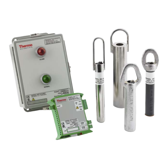
RAMSEY MERCURY FREE TILT SENSORS
FOR NON-HAZARDOUS AREAS
CONTROL UNITS
Model 20-35-NM-F
Model 20-35-NM-DIN
Manufacturer:
Thermo Fisher Scientific
th
501 90
Avenue NW
55433 Minneapolis, MN (USA)
(800) 445-3503
Mercury Free Tilt Sensor
User's Guide
REC 4274 Rev. C
PROBES
Model 20-54-NM-SS
Model 20-52-NM
Model 20-59-NM
Model 20-55-NM-P
Part Number 092241
i
Advertisement
Table of Contents


Need help?
Do you have a question about the 20-35-NM-F and is the answer not in the manual?
Questions and answers