
Related Manuals for Rosslare AC-A41


Summary of Contents for Rosslare AC-A41
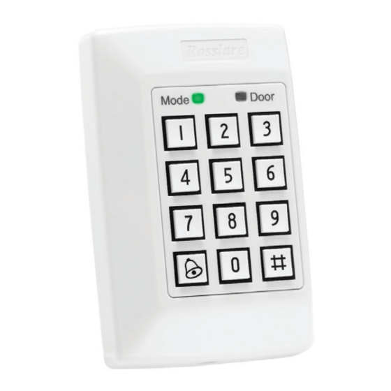
- Page 1 2013 June AC-A4x Family Indoor Standalone Controller Installation and Programming Manual Models: AC-A41 AC-A42...
- Page 2 ROSSLARE. ROSSLARE reserves the right to revise and change this document at any time, without being obliged to announce such revisions or changes beforehand or after the fact.
-
Page 3: Table Of Contents
Table of Contents Table of Contents Introduction ..............8 Reader/Controller Types............8 Key Features ................8 Equipment ................9 Additional Equipment .............. 9 Technical Specifications ..........10 Installation ..............11 Mounting ................11 Wiring .................. 13 Normal, Secure, and Master Users ......15 Modes of Operation .......... - Page 4 Table of Contents 11.3 Changing the Open Code ............25 11.4 Changing the Auxiliary Code ..........25 11.5 Changing the Programming Code .......... 26 11.6 Changing the Normal/Secure Code ........27 11.7 Changing the Normal/Bypass Code and Door Chime Settings .. 27 11.8 Defining the Auxiliary Input and Output .........
- Page 5 List of Figures List of Figures Figure 1: AC-A4x Controller – Labeled Diagram ..........11 Figure 2: AC-A4x Controller – Mounting Holes and Terminal Blocks ....12 Figure 3: Wiring the Lock Strike Relay and REX ..........13 Figure 4: Wiring the Auxiliary Input and Output ..........13 Figure 5: Wiring the BL-D40 External Sounder ..........
- Page 6 List of Tables List of Tables Table 1: Programming Menus................23 Table 2: Quick Reference Guide for Auxiliary Mode Setting ......30 AC-A4x Installation and Programming Manual...
- Page 7 ROSSLARE ENTERPRISES LIMITED and/or its related companies and/or subsidiaries’ (hereafter:"ROSSLARE") exclusive warranty and liability is limited to the warranty and liability statement provided in an appendix at the end of this document.
-
Page 8: Introduction
The units accept up to 500 users and allow entry via a personal identification number (PIN) and/or by presenting a proximity card Reader/Controller Types The two types of units described in this manual are: Keypad Type PIN Proximity AC-A41 Standard AC-A42 Standard ... -
Page 9: Equipment
Request to Exit (REX) button – Normally Open Type; switch is closed when pressed. BL-D40 External Sounder (optional) – Provides siren, bell, and chime functions to AC-A4x Other Rosslare accessories can be found at Rosslare's website: http://www.rosslaresecurity.com AC-A4x Installation and Programming Manual... -
Page 10: Technical Specifications
Length x Width x Depth (122 x 75 x 24 mm) Weight 0.3 lb (140 g) * Measured using Rosslare Proximity Card (AT-11/12) or equivalent. Range also depends on electrical environment and proximity to metal AC-A4x Installation and Programming Manual... -
Page 11: Installation
Installation Installation Mounting Before starting, select the location to mount the AC-A4x controller. This location should be at shoulder height and on the same side as the door handle. The controller is designed to be easily mounted onto a US Gang Box. 1. -
Page 12: Figure 2: Ac-A4X Controller - Mounting Holes And Terminal Blocks
Installation Figure 2: AC-A4x Controller – Mounting Holes and Terminal Blocks AC-A4x 3. Pass the wires through the exit/entry holes and attach them to the controller's terminal blocks, as shown in Figure 3 and Figure 4. Replace the controller’s bezel and replace the factory default screw with the security screw that is provided in the installation kit. -
Page 13: Wiring
Installation Wiring Three typical wiring diagrams are shown in Figure 3 through Figure 5. Figure 3: Wiring the Lock Strike Relay and REX AC-A4x Figure 4: Wiring the Auxiliary Input and Output AC-A4x AC-A4x Installation and Programming Manual... -
Page 14: Figure 5: Wiring The Bl-D40 External Sounder
Installation Figure 5: Wiring the BL-D40 External Sounder AC-A4x For other wiring diagram examples, refer to the support section of the Rosslare website: http://www.rosslaresecurity.com/. AC-A4x Installation and Programming Manual... -
Page 15: Normal, Secure, And Master Users
Normal, Secure, and Master Users Normal, Secure, and Master Users The AC-A4x series accept up to 500 users and provide entry via the use of proximity cards and/or PIN codes. Each user is provided with two code memory slots: Memory Slot 1 (Primary code) and Memory Slot 2 (Secondary code). -
Page 16: Modes Of Operation
Modes of Operation Modes of Operation • In the Operation chapter, “code” refers to a PIN code or proximity card depending on the unit you have. • Memory slots can be a proximity card or PIN code depending on the unit you have. The AC-A4x series have three modes of operation: Mode Door... -
Page 17: Changing The Modes Of Operation
Changing the Modes of Operation Changing the Modes of Operation Changing from Normal to Secure Mode The default factory setting for the Normal/Secure code is 3838. To change from Normal to Secure mode: Mode Door 1. Enter the 4-digit Normal/Secure code. Green Mode Door... -
Page 18: Changing From Normal To Bypass Mode
Changing the Modes of Operation Changing from Normal to Bypass Mode See Section 11.7 to create/modify the Normal/Bypass code. To change from Normal to By pass mode: Mode Door 1. Enter the 4-digit Normal/Bypass code. Green Mode Door The Mode LED flashes orange. Orange 2. -
Page 19: Auxiliary Input And Output
Auxiliary Input and Output Auxiliary Input and Output For optimum usability in different applications, the controller’s auxiliary input and output can be configured in 8 different modes of operation (see Section 11.8). AC-A4x Installation and Programming Manual... -
Page 20: Rex Button
REX Button REX Button The REX button is used to open the door without the use of proximity card or PIN code, and must be located inside the premises to be secured. It is usually located in a convenient location, such as inside the door or at a receptionist's desk. -
Page 21: Case And Back Tamper
Case and Back Tamper Case and Back Tamper If the case of the controller is opened or the controller is removed from the wall, a tamper event is triggered and a coded tamper signal is sent to a BL-D40, PS-X41 Series, or PS-X42 Series Power Supply, or to another compatible device. -
Page 22: Bl-D40 External Sounder
The BL-D40 External Sounder is compatible with the AC-x31, AC-x32, AC-x41, and AC-x42 series of standalone controllers. (For a more up- to-date list of compatible products, check the Rosslare website at www.rosslaresecurity.com.) It is designed to operate indoors and is installed within the premises to be secured. -
Page 23: Programming The Ac-A4X
Programming the AC-A4x Programming the AC-A4x You can program the AC-A4x solely via the unit's keypad-driven programming menu system. To reach the programming menu system, first place the unit into Programming mode (see Section 11.1). During the AC-A4x manufacturing process, certain codes and settings are pre-programmed. -
Page 24: Entering Programming Mode
Programming the AC-A4x 11.1 Entering Programming Mode To enter Programming mode: 1. Press # for two seconds. The Mode LED turns off and the Door LED Mode Door turns red. 2. Enter your 4-digit Programming code. If the Programming code is valid, the door Mode Door LED turns green and the unit goes into... -
Page 25: Changing The Open Code
Programming the AC-A4x 11.3 Changing the Open Code The Open code is mainly used as a method to quickly test the Lock Strike Relay during installation. The default factory setting for Open code is 2580. When the first user is added to the controller, the default Open code is automatically deleted, and is ready for a new Open code to be re- entered. -
Page 26: Changing The Programming Code
Programming the AC-A4x To change the Aux iliary code: Mode Door 1. Enter Programming mode. Green 2. Press 2 to enter Menu 2. Mode Door The Mode LED turns orange. Green Orange 3. Enter the new 4-digit code that you want to set as the Auxiliary code. -
Page 27: Changing The Normal/Secure Code
Programming the AC-A4x The Programming code cannot be erased; code 0000 is invalid and does not erase the Programming code. 11.6 Changing the Normal/Secure Code To change the Normal/ Secure code: Mode Door 1. Enter Programming mode. Green 2. Press 4 to enter Menu 4. Mode Door The Mode LED flashes red. -
Page 28: Defining The Auxiliary Input And Output
Programming the AC-A4x 3. There are four different ways to program the Normal/Bypass code and door chime: Disable both Bypass code and the door chime. Enter the code 0000. Disable Bypass code and enable the door chime. Enter the code 0001. ... - Page 29 Programming the AC-A4x 3. Construct a code using the following instructions: Auxiliary Mode Auxiliary Setting Auxiliary Mode In addition to the Lock Strike Relay and Lock Strike REX, the controller features an Auxiliary Output Relay and an Auxiliary Input. The Auxiliary mode defines the function of the Auxiliary Input and Output.
- Page 30 Programming the AC-A4x Table 2: Quick Reference Guide for Auxiliary Mode Setting Aux. Mode Aux. Input Aux. Output Aux. Relay Aux. Settings Function Activated by (in seconds) REX-2 Valid code or REX-2 N.O. 01 to 99 Aux. Relay Release Time 00 Aux.
-
Page 31: Setting Fail Safe/Secure Operation, Tamper Siren Time, And Lock Strike Release Time
Programming the AC-A4x 11.9 Setting Fail Safe/Secure Operation, Tamper Siren Time, and Lock Strike Release Time Mode Door 1. Enter Programming mode. Green Press 6 to enter Menu 6. Mode Door The Mode LED flashes green. Green Green Construct the 4-digit code using the following instructions: First Digit ... -
Page 32: 11.10.3 Enrolling Primary And Secondary Codes
Programming the AC-A4x 11.10 Enrolling Primary and Secondary Codes 11.10.1 Primary Codes Primary codes can only be enrolled to an empty user slot, meaning a slot where there is no existing Primary code. Primary codes must be unique, meaning that one user's Primary code cannot be the same as another user's Primary code. -
Page 33: Enrolling Primary And Secondary Codes Using The Standard Method
Programming the AC-A4x 11.10.4 Enrolling Primary and Secondary Codes Using the Standard Method To enroll primary and secondary codes using the Standard method: Mode Door 1. Enter Programming mode. Green Press 7 to enter Menu 7. Mode Door The Door LED turns orange. Orange 3. -
Page 34: Enrolling Secondary Codes Using The Code Search Method
Programming the AC-A4x b. Present a Proximity card (AC-A42) or enter the 4-digit PIN that you want to assign as the Primary or Secondary code for this slot number. If the Proximity card or PIN entered is valid, the Mode LED stops flashing and the controller is ready for you to enter the next 3-digit slot number (refer to Step a) that you want to assign a code to. -
Page 35: Deleting Primary And Secondary Codes
Programming the AC-A4x Mode Door 5. The Mode LED flashes red. Red Orange If the Primary code entered is not valid, a long beep is emitted and the unit continues to wait for a valid Primary code. 6. Present the Proximity card or enter the 4-digit PIN code to be used as the Secondary code: If the Secondary code is valid, the controller beeps three times and returns to Normal mode. -
Page 36: Deleting Primary And Secondary Codes Using The Code Search Method
Programming the AC-A4x The Mode LED flashes red indicating the controller is waiting for the Programming code to confirm the deletion. Mode Door If the user slot is empty, a long beep is Red Orange emitted and the unit returns to Normal mode. -
Page 37: Lock Strike Relay And Auxiliary Relay Code Assignment
Programming the AC-A4x The controller is now waiting for the Primary code of the user you want to delete. 4. Present the Proximity card or enter the 4- digit PIN code of the Primary code belonging to the user you want to delete. Mode Door The Mode LED flashes red. -
Page 38: Lock Strike Relay And Auxiliary Relay Code Assignment Using Standard Method
Programming the AC-A4x 11.12.1 Lock Strike Relay and Auxiliary Relay Code Assignment using Standard Method Mode Door 1. Enter Programming mode. Green 2. Press 9 to enter Menu 9. The Mode LED turns green and the Door Mode Door LED turns orange. Green Orange 3. -
Page 39: Return To Factory Default Settings
Programming the AC-A4x 3. Enter 000 for user slot access. Mode Door The Door LED flashes orange. Green Orange The controller is now waiting for the Primary code of the user. 4. Present the Proximity card or enter the primary code belonging to the user. -
Page 40: Replacing A Lost Programming Code
Programming the AC-A4x If the Programming code is valid, all memory is erased, three beeps are emitted, and the controller returns to Normal mode. If the Programming code is invalid, a long beep is emitted, and the controller returns to Normal mode without erasing the memory of the controller. -
Page 41: Limited Warranty
ARRANTY EMEDY OVERAGE In the event of a breach of warranty, ROSSLARE will credit Customer with the price of the Product paid by Customer, provided that the warranty claim is delivered to ROSSLARE by the Customer during the warranty period in accordance with the terms of this warranty. Unless otherwise requested by a ROSSLARE representative, return of the failed product(s) is not immediately required. - Page 42 ROSSLARE or a ROSSLARE authorized service center. XCLUSIONS AND IMITATIONS ROSSLARE shall not be responsible or liable for any damage or loss resulting from the operation or performance of any Product or any systems in which a Product is incorporated. This warranty shall not...
- Page 43 In no event shall ROSSLARE be liable for damages in excess of the purchase price of the product, or for any other incidental, consequential or special damages, including but not limited to loss of...
- Page 44 Tel: +86 755 8610 6842 Canada Fax: +86 755 8610 6101 support.cn@rosslaresecurity.com Rosslare Security Products, Inc. Southlake, TX, USA India Toll Free: +1-866-632-1101 Rosslare Electronics India Pvt Ltd. Local: +1-817-305-0006 Tel/Fax: +91 20 40147830 Fax: +1-817-305-0069 Mobile: +91 9975768824 support.na@rosslaresecurity.com sales.in@rosslaresecurity.com...
Need help?
Do you have a question about the AC-A41 and is the answer not in the manual?
Questions and answers