Advertisement
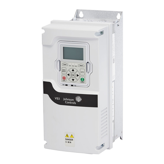
Variable Speed Drives Series III
Quick Start Guide
Effective April 2018
New Information
CONTENTS
Step 2-Keypad Operation Overview . . . . . . . . . . . . . . .
Step 3-Menu Navigation . . . . . . . . . . . . . . . . . . . . . . . .
Step 4-Startup Wizard . . . . . . . . . . . . . . . . . . . . . . . . . .
Step 5-Standard Parameter List . . . . . . . . . . . . . . . . . . 10
Appendix A-Fault and Warning Codes . . . . . . . . . . . . . 40
1
3
6
8
Advertisement


Need help?
Do you have a question about the VS3-005-4-UL1-0 and is the answer not in the manual?
Questions and answers