Table of Contents
Advertisement
Configuration Instructions
CONTENTS
SAFETY CONSIDERATIONS . . . . . . . . . . . . . . . . . . . . . . 1
GENERAL . . . . . . . . . . . . . . . . . . . . . . . . . . . . . . . . . . . . . . . . 2
INSTALLATION . . . . . . . . . . . . . . . . . . . . . . . . . . . . . . . . 2-26
General . . . . . . . . . . . . . . . . . . . . . . . . . . . . . . . . . . . . . . . . . . 2
Zone Controller Hardware . . . . . . . . . . . . . . . . . . . . . . . . 2
Field-Supplied Hardware . . . . . . . . . . . . . . . . . . . . . . . . . 2
• DUCT AIR TEMPERATURE SENSOR
Mount Zone Controller . . . . . . . . . . . . . . . . . . . . . . . . . . . 4
• LOCATION
• MOUNTING
Connect the Power Transformer. . . . . . . . . . . . . . . . . . 5
Install Sensors . . . . . . . . . . . . . . . . . . . . . . . . . . . . . . . . . . 15
INSTALLATION
INSTALLATION
• SUPPLY AIR TEMPERATURE (33ZCSENSAT)
SENSOR INSTALLATION
INSTALLATION
Remote Occupancy Contact. . . . . . . . . . . . . . . . . . . . . 21
Connect the Outputs . . . . . . . . . . . . . . . . . . . . . . . . . . . . 21
Modulating Baseboard Hydronic Heating . . . . . . . . 23
Communication Bus . . . . . . . . . . . . . . . . . . . . . . . . . . 23
START-UP . . . . . . . . . . . . . . . . . . . . . . . . . . . . . . . . . . . . 26-29
Perform System Checkout . . . . . . . . . . . . . . . . . . . . . . 26
Network Addressing . . . . . . . . . . . . . . . . . . . . . . . . . . . . 27
Initial Operation and Test. . . . . . . . . . . . . . . . . . . . . . . . 27
Fan and Heat Configuration and Test. . . . . . . . . . . . 27
System Balancing . . . . . . . . . . . . . . . . . . . . . . . . . . . . . . . 27
Status Table . . . . . . . . . . . . . . . . . . . . . . . . . . . . . . . . . . . . . 28
CONFIGURATION TABLES . . . . . . . . . . . . . . . . . . . 29-39
Alarm Configuration Table . . . . . . . . . . . . . . . . . . . . . . 29
Terminal Service Configuration Table . . . . . . . . . . . 30
Damper Service Configuration Table . . . . . . . . . . . . 33
Holiday Configuration Table. . . . . . . . . . . . . . . . . . . . . 33
Linkage Configuration Table . . . . . . . . . . . . . . . . . . . . 33
Language Configuration Table . . . . . . . . . . . . . . . . . . 35
Manufacturer reserves the right to discontinue, or change at any time, specifications or designs without notice and without incurring obligations.
PC 111
Book 1
4
Tab
11a 13a
Installation, Start-Up and
Part Number 33ZCVVTZC-01
Page
) SENSOR
2
Catalog No. 533-30011
Printed in U.S.A.
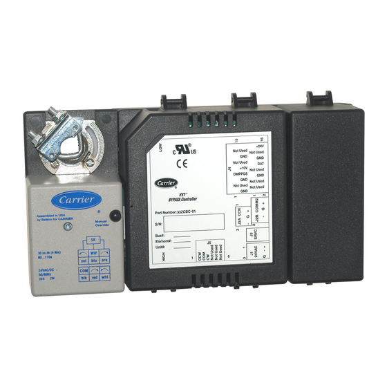
3V™ Control System
VVT® Zone Controller
Pressure Dependent Control
Master Service Configuration Table . . . . . . . . . . . . . 35
Time Schedule Configuration Table . . . . . . . . . . . . . 36
Option Service Configuration Table . . . . . . . . . . . . . 37
Set Point Configuration Table . . . . . . . . . . . . . . . . . . . 39
MAINTENANCE TABLES . . . . . . . . . . . . . . . . . . . . . 40-51
System Pilot Maintenance Table. . . . . . . . . . . . . . . . . 40
System Pilot Alternate Maintenance Table. . . . . . . 40
Linkage Maintenance Table . . . . . . . . . . . . . . . . . . . . . 41
Master Zone Maintenance Table . . . . . . . . . . . . . . . . . 43
Time Schedule Maintenance Table . . . . . . . . . . . . . . 44
System Commissioning Maintenance Table . . . . . 45
Zone Status Maintenance Table . . . . . . . . . . . . . . . . . 47
Zone Device Maintenance Table . . . . . . . . . . . . . . . . . 47
Zone Maintenance Table . . . . . . . . . . . . . . . . . . . . . . . . 47
Zone Commissioning Maintenance Table . . . . . . . 50
OPERATION. . . . . . . . . . . . . . . . . . . . . . . . . . . . . . . . . . 51-54
System Mode Selection . . . . . . . . . . . . . . . . . . . . . . . . . 51
Linkage . . . . . . . . . . . . . . . . . . . . . . . . . . . . . . . . . . . . . . . . . 52
System Modes . . . . . . . . . . . . . . . . . . . . . . . . . . . . . . . . . . 53
Air Terminal Modes . . . . . . . . . . . . . . . . . . . . . . . . . . . . . 53
APPENDIX A - SYSTEM OPERATION
FLOW CHARTS . . . . . . . . . . . . . . . . . . . . . . . . . . . . 55-58
SAFETY CONSIDERATIONS
SAFETY NOTE
Air-conditioning equipment will provide safe and reli-
able service when operated within design specifications.
The equipment should be operated and serviced only by
authorized personnel who have a thorough knowledge
of system operation, safety devices and emergency
procedures.
Good judgement should be used in applying any
manufacturer's instructions to avoid injury to personnel or
damage to equipment and property.
Disconnect all power to the unit before performing mainte-
nance or service. Unit may automatically start if power is
not disconnected. Electrical shock and personal injury
could result.
If it is necessary to remove and dispose of mercury contac-
tors in electric heat section, follow all local, state, and
federal laws regarding disposal of equipment containing
hazardous materials.
Form 33ZC-13SI
Pg 1
405
10-04
Replaces: New
Advertisement
Table of Contents

Related Manuals for Carrier VVT 33ZCVVTZC-01


Summary of Contents for Carrier VVT 33ZCVVTZC-01
-
Page 1: Table Of Contents
Modulating Baseboard Hydronic Heating ..23 procedures. Connect the Carrier Communicating Network Good judgement should be used in applying any Communication Bus ......23 manufacturer’s instructions to avoid injury to personnel or... -
Page 2: General
GENERAL Carrier’s network software can be connected to the system at the SPT sensor if Carrier network communication wiring is The zone controller is a single duct, fan powered, Variable run to the SPT sensor. The network software can be used to Volume and Temperature (VVT®) terminal control with a... - Page 3 SOFTWARE SYSTEM ROOFTOP ROOFTOP PILOT UNIT UNIT BRIDGE (RECOMMENDED) SECONDARY BUS VVT ZONE CONTROLLER EQUIPPED AIR TERMINAL MAXIMUM OF 32 PER ROOFTOP/LINKAGE MASTER MAXIMUM OF 8 LINKAGE MASTERS PER BUS DATA COLLECTION OPTION Fig. 1 — Typical Carrier Linkage System...
-
Page 4: Indoor Air Quality
Duct Air Temperature Sensor is required for cooling only appli- existing hardware. cations on non-33CS or non-Carrier dampers. The sensor is used 2. Round or rectangular damper brackets may be attached to for supply air monitoring. The sensor has an operating range of the damper to provide a clearance for the damper bearing –40 to 245 F (–40 to 118 C) and includes a mounting grommet... -
Page 5: Connect The Power Transformer
9. If the damper has less than 90 degrees of travel between ALLOW 12” CLEARANCE FOR SERVICE the fully open and fully closed positions, then a mechani- ACCESS TO CONTROL BOX cal stop must be set on the actuator. The mechanical stop prevents the damper from opening past the maximum 3”... - Page 6 1104...
- Page 7 24VAC 1104...
- Page 8 24VAC 1104...
- Page 9 24VAC 1104...
- Page 10 24VAC 1104...
- Page 11 24VAC 1104...
- Page 12 24VAC 1104...
- Page 13 24VAC 1104...
- Page 14 24VAC 1104...
-
Page 15: Install Sensors
SEN terminal controller. There are two types of SPT sensors available from block of the sensor. Carrier: the 33ZCT55SPT space temperature sensor with timed override button and the 33ZCT56SPT space temperature sen- b. Connect another wire from the cable (BLACK) to sor with timed override button and set point adjustment. - Page 16 Before wiring the Carrier proprietary network connection, lug on the shield drain wire. Install this lug under refer to the Connect the Carrier Communicating Network the mounting screw in the upper right corner of the Communication Bus section on page 23, for communication controller (just above terminal T1).
-
Page 17: System Pilot
Wiring when distance between zone controller and space temperature sensor is 100 feet or less 100 FT. MAXIMUM COMM BUS 3 COND COMM CABLE (TYP) 2 COND TWISTED CABLE OR 3 COND CABLE (TEMP SENSOR WIRING) (TYP) ZONE AIR TERMINAL CONTROLLER UNIT (TYP) C o o... -
Page 18: Primary Air Temperature Sensor
Sensor is required for cooling only applications on non- 4. Neatly bundle and secure excess wire. Carrier dampers. The sensor is used for supply air monitoring. 5. Using electrical tape, insulate any exposed lead to prevent The sensor has an operating range of –40 to 245 F (–40 to shorting. - Page 19 Fig. 20 — Primary Air Temperature Sensor Installation (Unit Discharge Location) Fig. 19 — Primary Air Temperature Sensor (Part Number 33ZCSENPAT) .225/ .245 (5.72/6.22) 0.06 75.0 1.00 (1.5) (1905) (25.4) 1.25 (31.8) NOTE: Dimensions are in inches (millimeters). Fig. 21 — 33ZCSENSDAT Duct Sensor...
-
Page 20: Indoor Air Quality Sensor Installation
Do not run sensor or relay wires in the same conduit or race- The sensor part number is 33ZCSENCO2. To mount the way with Class 1 AC or DC service wiring. Do not abrade, cut, sensor, refer to the installation instructions shipped with the or nick the outer jacket of the cable. -
Page 21: Humidity Sensor (Wall-Mounted)
The sensor must be mounted vertically on the wall. The Carrier logo should be oriented correctly when the sensor is properly mounted. DO NOT mount the sensor in drafty areas such as near heat- ing or air-conditioning ducts, open windows, fans, or over heat sources such as baseboard heaters, radiators, or wall-mounted light dimmers. -
Page 23: Modulating Baseboard Hydronic Heating
→ Connect the Carrier Communicating Net- suppressor in each building where the cable enters or exits (one work Communication Bus —... -
Page 26: Start-Up
If hot water re- heat is used, check piping and valves against job draw- Changes can be made using the System Pilot or Carrier soft- ings. ware. During start-up, the Carrier software can also be used to verify communication with each zone controller. -
Page 27: Network Addressing
9. Check to be sure the area around the air source is clear of Maintenance Screen, select the Zone Commissioning construction dirt and debris. Table and force the Commissioning Mode point to Enable. Then select the Damper Cal point and force this 10. -
Page 28: Status Table
The screens shown may be displayed differently heat source. Measured by a 10 kΩ thermistor (Type II). This when using different Carrier software. See Table 4. temperature may be used to control the maximum discharge air to the space when local heat is active. The local SAT Installed TERMINAL MODE —... -
Page 29: Configuration Tables
Display Units Discrete ASCII Default Value Disable ALARM ROUTING CONTROL — This decision indicates which Carrier Proprietary Network system software or devices Display Range Disable/Enable will receive and process alarms sent by the zone controller. This Network Access Read/Write decision consists of eight digits each can be set to zero or one. A REMOTE START —... -
Page 30: Terminal Service Configuration Table
Clockwise cluded in the average demand calculations. Rotation: Range Close/Open NOTE: Carrier sizes 12, 14, and 16 are oval. Default Value Close 1104... - Page 31 → Table 6 — Terminal Service Configuration Table DESCRIPTION VALUE UNITS NAME COOLING Terminal Type TERMTYPE 1 = Single Duct 2 = Parallel Fan 3 = Series Fan Primary Inlet Size Inlet Diameter (Inches) RNDSZ Inlet Area (Sq. In.) Damper PID Proportional Gain 10.0 Integral Gain...
- Page 32 HEAT TYPE — This configuration is used to define the type heat is deactivated (in a parallel terminal) until the parallel fan of heat installed on the terminal. A 0 or 1 is equal to None. A 2 is deactivated. This allows the fan to circulate air and remove is equal to Two Position.
-
Page 33: Damper Service Configuration Table
It also includes Carrier Network Function Configuration used the equipment mode is cooling (or fan only), or free cooling for collecting data from multiple controllers and finding the and the space requirements for cooling are at a maximum. - Page 34 AIR SOURCE BUS AND ELEMENT NUMBER — The Air Air Source Source Bus and Element Number configurations define the Bus Number: Range 0 to 239 address of the air source providing conditioned air to the zones Default Value controlled by the linkage coordinator. If the address is left at Air Source zero, the linkage coordinator will look for a primary air sensor Element Number: Range...
-
Page 35: Language Configuration Table
SYSTEM BYPASS EXISTS — This decision is used to tell Destination the linkage coordinator that an optional bypass controller does Element Number: Units none or does not exist in this system. If this decision is set to Yes, the Range 0-239 (0 = disabled) linkage coordinator will attempt to communicate with a bypass Default Value... -
Page 36: Time Schedule Configuration Table
Table 10 — Master Service Configuration Table DESCRIPTION VALUE UNITS NAME Cool Start Avg. Demand CSA_DMD Cool Mode Hysteresis C_HYST Heat Start Avg. Demand HSA_DMD Heat Mode Hysteresis H_HYST System Mode Reselect RESELECT Cool Time Guard Timer C_MOD_TG Heat Time Guard Timer H_MOD_TG Cont. -
Page 37: Option Service Configuration Table
If the current occupancy period is unoccupied when the GLOBAL SCHEDULE MASTER — The Global Schedule occupancy override is initiated, the mode will change to Master configuration allows the Occupancy Schedule to be used occupied for the duration of the number of hours downloaded. as a Global Schedule Master (Occupancy Schedules 65-99). - Page 38 Table 11 — Time Schedule Configuration Table DESCRIPTION VALUE UNITS NAME Manual Override Hours hours OVRD Period 1 DOW (MTWTFSSH) 11111111 DOW1 Occupied from 00:00 OCC1 Occupied to 24:00 UNOCC1 Period 2 DOW (MTWTFSSH) 00000000 DOW2 Occupied from 00:00 OCC2 Occupied to 24:00 UNOCC2...
-
Page 39: Set Point Configuration Table
LOADSHED OFFSET ADJUST — This decision is used to DCV LOW REF (PPM) — This decision is used to define the configure an amount by which the Occupied Heating and value in parts per million that correlate to the low voltage read- Occupied Cooling set points will be relaxed in response to a ing from the demand control ventilation sensor. -
Page 40: Maintenance Tables
Table 14. This screen can be accessed through the maintenance Cool Set Point: Display Units F (C) option on the System Pilot or through Carrier network software. Display Range 45.0 to 99.9 Network Access Read/Write TERMINAL MODE — This variable will display the current operating mode of the terminal, if linkage is available, or the UNOCCUPIED HEAT SET POINT —... -
Page 41: Linkage Maintenance Table
Table (LINKMNT) displays linkage data for the Linkage lers. This function is supported by all Carrier equipment which Coordinator zone controller. This data includes air source oper- perform linkage. - Page 42 Table 16 — Linkage Maintenance Table DESCRIPTION VALUE UNITS STATUS FORCE NAME Zone Linkage Air Source Bus # ASBUSNUM Air Source Element # ASDEVADR Master Zone Element # MZDEVADR Operating Mode COOLING ASOPMODE Air Source Supply Temp 55.0 ASTEMP Start Bias Time STRTBIAS Occ Heat Setpt 68.0...
-
Page 43: Master Zone Maintenance Table
Master Zone Maintenance Table — Heating and Cooling set points. When in unoccupied mode, the The Master Zone demand will be directly related to configured Unoccupied Maintenance Table (MZNMAINT) displays variables used by Heating and Cooling set points. the Linkage Coordinator zone controller when determining the system mode (heat/cool/vent). -
Page 44: Time Schedule Maintenance Table
MAX COOL DEMAND — This variable displays the maxi- Max Heat mum cooling demand of all occupied linked zones, taking into Demand Zone: Display Range 0 to 31 consideration the size of each zone as configured in the Network Access Read Only Terminal Service Configuration Table. -
Page 45: System Commissioning Maintenance Table
Table 18 — Time Schedule Maintenance Table DESCRIPTION VALUE UNITS NAME Mode MODE Current Occupied Period PERIOD Override in Progress OVERLAST Override Duration OVERDURA Occupied Start Time 08:00 OCCSTART Unoccupied Start Time 18:00 UNSTART Next Occupied Day NXTOCCD Next Occupied Time 00:00 NXTOCCT Next Unoccupied Day... - Page 46 Table 19 — System Commissioning Maintenance Table DESCRIPTION VALUE UNITS STATUS FORCE NAME Commissioning Mode Disable Enable/Disable SCMOD Auto-Disable Timer SCTIME All Zone Dampers to Max Disable Enable/Disable ZD_MAX All Zone Dampers to Min Disable Enable/Disable ZD_MIN Position Single Zone Disable Enable/Disable ZD_SING...
-
Page 47: Zone Status Maintenance Table
Position Single Zone is Enabled. Force this • PIZone = pressure independent zone value to the desired minimum or maximum damper position. • Other = other Carrier Network device found Zone (1-32) NOTE: If this zone controller is not a Linkage Coordinator, the... - Page 48 Table 20 — Zone Status Maintenance Table DESCRIPTION VALUE UNITS STATUS FORCE NAME Air Source Status Failed AIRSRCE Bypass Comm Status Failed ZD_CS00 Zone 1 Comm Status Com OK ZD_CS01 Zone 2 None ZC_CS02 Zone 3 None ZC_CS03 Zone 4 None ZC_CS04 Zone 5...
- Page 49 Table 21 — Zone Device Maintenance Table DESCRIPTION VALUE UNITS STATUS FORCE NAME Bypass Device Type Bypass ZD_DEV00 Zone 1 Device Type Master ZD_DEV01 Zone 2 PD Zone ZD_DEV02 Zone 3 PD Zone ZD_DEV03 Zone 4 None ZD_DEV04 Zone 5 None ZD_DEV05 Zone 6...
-
Page 50: Zone Commissioning Maintenance Table
LINKAGE MASTER — This variable displays if this zone Temperature controller is functioning as a Linkage Coordinator. Control Position: Display Units Display Range 0 to 100 Linkage Master: Display Range No/Yes Network Access Read Only Network Access Read Only DCV DAMPER % — This variable displays the damper set TIMED OVERRIDE IN EFFECT —... -
Page 51: Operation
Table 23 — Zone Commissioning Maintenance Table DESCRIPTION VALUE UNITS STATUS FORCE NAME Commissioning Mode Disable CMODE Damper Cal Disable CALIBRAT Fan Override Disable FANOVER Heating Override Disable HEATOVER Damper Position %OPEN DMPPOS Supply Air Temperature 67.1 Damper Cal Status Normal CAL_ALRM COMMISSIONING MODE —... -
Page 52: Linkage
Linkage operation in air sources that Avg. Demand or Cool Start Avg. Demand in the Master [Link- have Carrier communicating network controls such as age Coordinator] Service Configuration table), the system will 48/50HG, 48/50A, and 48/50Z Product Integrated Controls start in that mode. -
Page 53: Non-Linkage Controlled Air Sources
All its optional Pressurization input closed, it will transmit this the listed modes are available if there is a linked Carrier mode to the Linkage Coordinator. If this mode is active then all... - Page 54 Status Display table to Disable. Contact your local configured for parallel fan, the fan will be energized whenever Carrier Controls representative if you need assistance with this the there is a demand for heat the system mode is not Heating application.
-
Page 55: Flow Charts
APPENDIX A — SYSTEM OPERATION FLOW CHARTS → 3V™ System Mode Selection LEGEND Enter Is ACD < — Avg Cool Demand Send Linkage data — Avg Heat Demand (CSA_DMD —C_HYST) OZT = RZSPT CLO_SPT — OAT Cooling Lockout Setpoint Scan zone controllers in system CSA_DMD —... - Page 56 3V™ Zone Damper Operation LEGEND Enter DMPPOS — Damper Position EVAC — Evacuation HSMR — Heat Submaster Reference DMPPOS = 70% — Proportional/Integral/Derivative Is system mode = Fan off if configured for Fan PRES — Pressurization OFF? Box Terminal Type —...
- Page 57 3V™ Zone Controller DCV Damper Control Logic LEGEND Enter — Demand Control Ventilation Sensor DCVSP — Demand Control Ventilation Setpoint DCVD — Demand Control Ventilation Damper Output MAXOUT — DCVD Configured Maximum Output Zone Occupied? Biased Occuped? Zone in Heat mode? DCVD = 0 Error = DCVSP - DCV...
- Page 58 3V™ Zone Controller Temperature Control Damper Logic LEGEND CCMR — Cooling Setpoint Enter — Demand Control Ventilation DCVD — DCV Damper Output — Zone Demand DMPPOS — Damper Position Lo c al DMD = HCMR — Heat Setpoint heat? — Space Temperature [System Mode] —...
- Page 60 Copyright 2004 Carrier Corporation Manufacturer reserves the right to discontinue, or change at any time, specifications or designs without notice and without incurring obligations. PC 111 Catalog No. 533-30011 Printed in U.S.A. Form 33ZC-13SI Pg 60 10-04 Replaces: New Book 1...
Need help?
Do you have a question about the VVT 33ZCVVTZC-01 and is the answer not in the manual?
Questions and answers