Table of Contents
Advertisement
Quick Links
Download this manual
See also:
Quick Manual
Advertisement
Table of Contents

Related Manuals for Teltonika TMT250


Summary of Contents for Teltonika TMT250
- Page 1 TMT250 User Manual v0.5...
-
Page 2: Table Of Contents
ASIC CHARACTERISTICS ......................12 ECHNICAL FEATURES ..............13 ECHNICAL NFORMATION ABOUT INTERNAL BATTERY ....................14 LECTRICAL CHARACTERISTICS CONNECTION ........................15 TMT250 : ............15 OW TO INSERT MICRO CARD INTO DEVICE TMT250 : ..............16 OW TO CONNECT BATTERY TO DEVICE TMT250 .................... - Page 3 5.12 ......................... 39 LUETOOTH 5.12.1 General functionality ....................39 5.12.2 How to connect Bluetooth Hands Free adapter to TMT250 device ......41 5.12.2.1 Bluetooth settings configuration ..................41 5.12.2.2 Connecting Bluetooth Hands Free adapter ..............43 5.12.3 Logging the TMT250 device using your mobile phone ........... 43 5.12.4...
- Page 4 7.2.6 SIM APN Username (ID=2002) ................64 7.2.7 SIM APN Password (ID=2003) ................. 64 7.2.8 Domain (ID=2004) ....................64 7.2.9 Target Server Port (ID=2005) .................. 64 7.2.10 Protocol (ID=2006) ....................65 7.2.11 Backup Server Domain (ID=2007) ................65 7.2.12 Backup Server Port (ID=2008) ................. 65 7.2.13 Backup Server Protocol (ID=2009) ................
- Page 5 ......................75 EATURES ARAMETERS 7.6.1 Alarm ........................75 7.6.1.1 Scenario Settings (ID=11710) ..................... 75 7.6.1.2 Send SMS To (ID=7245) ...................... 75 7.6.1.3 SMS Text (ID=8245) ......................75 7.6.1.4 Call Settings (ID=11711) ..................... 76 7.6.1.5 Call to (ID=11712) ......................76 7.6.2 Overspeeding scenario parameters ................
- Page 6 7.10.3 SMS Action ......................90 7.10.3.1 SMS Send to (7249) ......................90 7.10.3.2 SMS Text (8249) ....................... 91 7.10.4 Call Action ....................... 91 7.10.4.1 Call to (13010) ........................91 7.11 ......................... 91 LUETOOTH 7.11.1.1 BT Radio (ID=800)......................91 7.11.1.2 Local name (ID 801) ......................91 7.11.1.3 Local PIN (ID=802) ......................
-
Page 7: Introduction
1 INTRODUCTION Attention Operate the device in suitable conditions Do not use the device where mobile connectivity is forbidden. Road safety first Comply with local traffic laws, always hold your hands on a steering wheel when using a device. Your safety is of utmost importance when you drive. Interference All wireless devices are sensitive to electromagnetic interference, as a result wireless devices affect the performance of each other. -
Page 8: Brief Description
GNSS receiver is able to identify current location and send it to an operations center or a person. In case of an emergency the device can activate the alarm function. TMT250 can also be used as a real-time navigator if the computer has special software installed. Device is able to execute various tasks through GSM network and GNSS system. - Page 9 ▪ GNSS – Global Navigation Satellite System: a system with global coverage that uses satellites to provide autonomous geo-spatial positioning. ▪ GPS – Global Positioning System: a worldwide satellite navigational system formed by 24 satellites orbiting the earth and their corresponding receivers on the earth. ▪...
- Page 10 connection and exchange streams of data. TCP guarantees delivery of data and also guarantees that packets will be delivered in the same order in which they were sent. ▪ TMO - Timeout ▪ UDP – User Datagram Protocol – a connectionless protocol that, like TCP, runs on top of IP networks.
-
Page 11: Basic Description
2 BASIC DESCRIPTION TMT250 is a tracking terminal with GNSS and GSM connectivity, which is able to collect device position parameters and status and transfer them via GSM network to the server. This device is perfectly suitable for applications, which require the acquisition of remote object locations. -
Page 12: Technical Features
Battery charge current: average 700 mA; Operation temperature: -25 °C .. +55 °C Storage temperature: -40 °C .. +70 °C Storage relative humidity: 5 .. 95 % (no condensation) Energy consumption has been tested by running TMT250 on battery (4.2 V). -
Page 13: Technical Information About Internal Battery
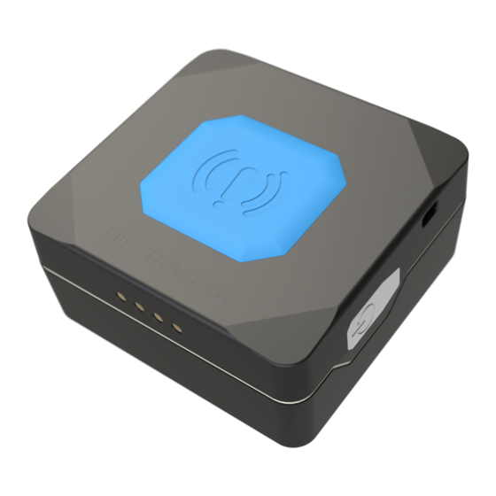
Figure 1 TMT250 top and side view & dimensions (tolerance ±2mm) Technical Information about internal battery Table 1. Li –ion rechargeable battery, 3.8 V, 800 mAh Internal back-up Charging Battery voltage V Nominal capacity (mAh) battery er(Wh) temperature °C Li-ion rechargeable 3.04... -
Page 14: Electrical Characteristics
Electrical characteristics Table 2. TMT250 electrical characteristics Value Characteristic description Supply Voltage: Min. Typ. Max. Unit In recommended operating conditions V DC... -
Page 15: Connection
Attach cover. Tighten the screws. Device is ready to use. Note: SIM card insertion/removal must be performed when TMT250 device is powered off – with external voltage and battery disconnected. Otherwise SIM card may be damaged. -
Page 16: How To Connect Battery To Tmt250 Device
How to connect battery to TMT250 device: Remove 4 screws and remove TMT250 Find the battery glued to the cover. cover. Connect battery and attach cover. Tighten the screws. Device is ready to use. -
Page 17: Installing Tmt250 Drivers
Drivers: Please download COM Port drivers from Teltonika website: http://avl1.teltonika.lt/downloads/FMB1/MS_USB_ComPort_Driver_exe_v1.1032.3.zip Installing drivers: Extract and run MS_USB_ComPort_Driver_exe_v1.1032.3. This driver is used to control TMT250 device connected to the computer. Click Next in driver installation window: Figure 2 Driver installation window 1... - Page 18 This will launch device driver installation wizard. In the following window click Install: Figure 3 Driver installation window 2 Setup will continue installing drivers and eventually the confirmation window will appear. Click Finish to complete setup: Figure 4 Driver installation window 3 You are now ready to use the device on your computer.
-
Page 19: Operational Basics
▪ Movement by accelerometer is detected. 4.2.2 Deep Sleep mode When in deep sleep mode, TMT250 sets the GNSS receiver to sleep mode and turns off GSM/GPRS module (hence it is not possible to wake up device via SMS). Despite records with last known coordinate being saved and sent to AVL server (GSM/GPRS module is turned on to send data and then it is turned off), power usage is decreased to save vehicle's battery. -
Page 20: Online Deep Sleep Mode
Link Timeout parameter, so that TMT250 could close GPRS link; ▪ The difference between Send Period (Data Acquisition Mode settings) and Open Link Timeout must be more than 90 seconds, so that TMT250 could close GPRS link within at least 90 seconds;... -
Page 21: Mandown
When working in slave mode - Bluetooth can accept incoming pairing requests from external devices. NOTE: TMT250 supports ONE connection at a time. NOTE: TMT250 can see up to 10 available devices. If there are more than 10 devices the scanning list may change. Auto Geofence Auto Geofence is a feature that notifies the user if the object has left the zone that was generated within set radius around the device. -
Page 22: User Interface
GSM operator's information. If device GSM is unavailable, the device will not be able to send the data and TMT250 will start storing records to flash memory. It is possible to store up to 192000 data records with internal memory (when 100 MB are used to store records). -
Page 23: Main Buttons Description
Figure 6 TMT250 configurator main window when connected to it and successfully loaded parameters Figure 7 TMT250 status elements 5.1.1 Main Buttons description: Connect to device (Figure 7) – connects device. Load from device – loads configuration from device. Save to device – save configuration to device. -
Page 24: Keyword Sms (Gprs) Commands
▪ Records: how many records were sent to the server since last data reset, when the last record was sent and when the last server response was. ▪ SMS count: the amount of SMS messages TMT250 has received and the amount of SMS responses that were sent from the device. -
Page 25: Security Info
▪ Movement Settings, where user can configure movement start and stop delay values (in seconds); ▪ Time Synchronization settings, where user can choose which source(s) to use for TMT250 time synchronization. User has a choice to: use only one synchronization source (Disable... - Page 26 saved and GPS is turned off again. Alternatively, if configuration is set to After Position Fix, the device will try to obtain GPS fix before record saving takes place and then allow extra GPS search period to obtain fix. Failing to do so within GPS search period, GPS module will be turned back off and the record will be not saved at all.
-
Page 27: Gprs
Data Link Timeout is used to set termination timeout for link between TMT250 and AVL application. If TMT250 has already sent all records it waits for the new records before closing the link (except for Deep Sleep mode, for more information refer to Deep Sleep mode). If new records are generated during the period of this timeout and minimum count to send is reached, the records are sent to AVL application. -
Page 28: Sms/Call Settings
Essential fields in SMS/Call Settings are Login and Password. The login and password are used with every SMS sent to TMT250. If login and password are not set, in every SMS sent to TMT250 device two spaces before command have to be used (<space><space><command>). -
Page 29: Gsm Operators, Roaming, Blacklist Operator List
When Number Check Settings option is enabled, numbers with “+” symbols will be used as international and numbers without it - as local/unknown. TMT250 works in synchronized GPS time which is UTC+0, with this option customer can configure the time zone and get SMS messages with correct time. - Page 30 TMT250 will work in Unknown mode (make sure it is configured to allow data sending – GPRS context is enabled). If user wants TMT250 to not connect and work with a particular operator it has to be written to Operator Blacklist. Up to 50 operators may be entered to this list.
-
Page 31: Data Acquisition Mode Settings
Figure 12 Operator search functionality diagram. White list is Roaming Operator lists Data Acquisition Mode settings Data Acquisition modes are an essential part of TMT250 device, they are also highly configurable. Through configuration user defines how records will be saved and sent. There are three different modes: Home, Roaming and Unknown. - Page 32 Operator list, device will work in Unknown mode. This functionality allows having different AVL records to acquire and send parameter values when object is moving or standing still. TMT250 has 6 different modes. Operational logic is shown in Figure 13.
- Page 33 Note: Keep in mind that TMT250 operates in GMT:0 time zone, without daylight saving. TMT250 is able to collect records using four methods at the same time: time, distance, angle and speed based data acquisition: 1. Time based data acquisition (Min Period) – records are acquired every time when a...
- Page 34 Min. time period 2. Distance based data acquisition (Min Distance) – records are acquired when the distance between previous coordinate and current position is greater than a defined parameter value. Entering zero disables data acquisition based on distance. Min. distance 3.
-
Page 35: Features Settings
Features settings Three different scenarios can be selected in Features window. Figure 15 Scenarios configuration 5.9.1 Alarm This function can be only triggered by a button (Power Button or Alarm Button). When the alarm is triggered, an event with IO ID 236 is generated. Eventually an SMS will be sent and a call can be performed. -
Page 36: Over Speeding
5.9.2 Over Speeding This feature is used to prevent the driver from exceeding fixed speed and inspects the driver if needed. When vehicle speed exceeds maximum configured speed value the scenario is activated, and a record is generated. Scenario is activated until speed value decreases below the set parameter value. -
Page 37: Movement Event
5.9.4 Movement Event Movement Event functionality makes an eventual high priority record (and sends an optional SMS) when device is stationary or in motion (depending on configured "Mode") for set Timeout (added to "Movement Start/Stop Delays" accordingly). Timeout is a configured amount of time (in seconds) after which an eventual high priority record is generated. -
Page 38: Manual Geofence
Figure 20 Auto Geofence configuration 5.11 Manual Geofence TMT250 has 50 configurable Geofence zones and it can generate an event when a defined Geofence zone border is crossed. Frame border is an additional border around Geofence zone used to prevent false events when object stops on the border of the area and as a result records are made inside and outside the defined area because of GNSS errors. -
Page 39: Bluetooth
Y coordinate (latitude) for a Rectangular zone. Figure 22 Geofence configuration 5.12 Bluetooth 5.12.1 General functionality General functionality configures Bluetooth to work in slave mode. This mode allows any external device to connect to TMT250. - Page 40 TMT250 Bluetooth has several different Security Modes: ▪ PIN only – only Local PIN will be reacquired to complete connection to TMT250. ▪ PIN + MAC list – PIN and Authorized Devices MAC List will be checked against to allow connection to TMT250.
-
Page 41: How To Connect Bluetooth Hands Free Adapter To Tmt250 Device
TMT250 supports ONE connection at a time. TMT250 can see up to 10 available devices. If there are more than 10 devices, the list may change with each new scan. External Name parameter works as a substring, which allows user to enter a part of the full external device name. - Page 42 Figure 25 1 – Bluetooth settings; 2 – Enable Bluetooth; 3 – Bluetooth local name; 4 – Bluetooth security mode; 5 – Hands Free connection mode; 6 – External BT device name; 7 – Authorized Devices MAC list ▪ When device configuration is loaded press Bluetooth settings (Figure 24 position 1). ▪...
-
Page 43: Connecting Bluetooth Hands Free Adapter
Run app, click Find->Connect to your paired device. Now we need to send a command to TMT250 from Bluetooth terminal, type: ".log:1". Device will respond with "Debug enabled" and TMT250 log will show up. Do not forget to save the log file to mobile phone. -
Page 44: Device Debug Over Android Smartphone
800 The answer has to be 2, which means Enabled ( visible). ▪ Scan for visible BT devices using your Android smartphone and connect to your TMT250 device. Default TMT250 BT name is: TMT250_last_7_imei_digits Default PIN code is: 5555... - Page 45 ▪ Run Bluetooth Terminal. In menu press Connect button and select paired TMT250 device. To start log check CR and enter the command into terminal: .log:1 Wait ~10 minutes and press Save button in menu. You will find the saved log file in device folder My Files/Bluetooth Terminal, select log files, press Share via Email and send them to Teltonika support.
-
Page 46: Sms Events
This event can be triggered by every I/O element. When any of the I/O elements is triggered, TMT250 sends a configured SMS message to a defined phone number. If SMS events are activated but there are no numbers defined in GSM Predefined Numbers list (similarly as in Figure 26), then the device will not send any messages. -
Page 47: Sms Text
5.14 SMS Text The SMS Text field can be altered and any text can be entered. Maximum message length is 160 symbols (numbers, letters and symbols in ASCII, except for comma symbol ","). SMS Event Text may be either in default or composed format. Default format: Date, time, longitude, latitude, 'SMS text', value Example:... -
Page 48: I/Osettings
GPRS fails, it sends an AVL packet using SMS data if SMS data sending is enabled and the number is provided in SMS/Call Settings. High and Low levels define I/O value range. If I/O value enters or exits this range, TMT250 generates an event. Operand parameter defines when to generate event: On Exit, On Entrance, On Both, On Hysteresis or On Delta Change. -
Page 49: Operand On Entrance
Figure 29 On Exit operand logic 5.15.2 Operand On Entrance Record is generated when input value enters a range between low and high level limits. Figure 30 On Entrance operand logic 5.15.3 Operand On Both Record is generated by both On Exit and On Entrance operands' logic at same time. Current value <... -
Page 50: Operand On Hysteresis
Figure 32 Monitoring operand logic 5.15.5 Operand On Hysteresis Record is generated when input value crosses the high limit value from below the low limit value or vice versa. Figure 33 Hysteresis operand logic 5.15.6 Operand On Change Record is generated when input value changes. Figure 34 On change operand logic 5.15.7 Operand On Delta Change Record is generated when input value changes and the absolute change becomes equal to... -
Page 51: Avg Const (Averaging Parameter Description)
5.15.8 Avg const (Averaging parameter description) If Avg Const value is 10, new value must be present for 1 second to register the change to a new value. Internal sampling is done every 40 ms, so 25 samples are taken per second. To configure 5 seconds of averaging multiply 10 by 5 yielding 50 as Avg Const value. - Page 52 Name Type Trigger Reason Outgoing Call Periodic Outgoing call is in process Remote Connection Periodic Device is connected to the server Event One Off An event record is saved Panic Event One Off A panic event record is saved No GPS Fix Periodic Device tries to obtain valid GPS fix GPS Fix Periodic Device has valid GPS fix...
-
Page 53: Keyboard
5.17 Keyboard A virtual keyboard is based on two buttons: Alarm Button and Power Button. Each button has three click combinations and one Power Button-specific combination for power off: ▪ 1 Click – button is pressed once for no longer than two seconds. ▪... -
Page 54: Sms/Gprs Command List
Deep Sleep mode, it cannot arrive to TMT250 device because the GSM/GPRS module is disabled most of the time. TMT250 will receive the SMS/GPRS message when it exits Deep Sleep mode. If TMT250 is in GPS Sleep or Online Deep Sleep mode, sent SMS/GPRS message will arrive to the device. - Page 55 Command Description Response 7.# - MODE (0-TCP/1-UDP) countrecs Returns records number deleterecords Deletes all records from SD card battery Returns battery state info wdlog Returns all information about watchdog restarts defaultcfg Loads default configuration setkey # # Adds a new configuration keyword or changes the current one.
-
Page 56: Getinfo
Device IMEI Init Device initialization time Uptime Total up time (in seconds) Device MAC address Example: “Ver:02.00.01_06 GPS:AXN_3.80_3333_16070400,0000,, Hw:TMT250 Mod:4 IMEI:352094082042885 Init: 2017-6-16 5:54 Uptime: 16574 BT:31F5BFE66261”. 6.1.3 getstatus Response details Description Data Link Indicates module connection to server at the moment: 0 – Not connected, 1... -
Page 57: Getgps
Response details Description – Connected GPRS Indicates if GPRS is available at the moment Phone Voice Call status: 0 – Ready, 1 – Unavailable, 2 – Unknown, 3 – Ringing, 4 – Call in progress, 5 – Asleep SIM Status: 0 – Ready, 1 – PIN, 2 – PUK, 3 – PIN2, 4 – PUK2 When connected to GSM Operator: numerical ID of operator Signal GSM Signal Quality [0-5]... -
Page 58: Setparam
For example: getparam 2001 command will request APN name. Example answer: Param ID:2001 Value:wap 6.1.7 setparam Reads parameter value for a given ID that consists of 3 or 5 digits. A detailed list of parameters and identifiers can be found in the following chapter. For example: setparam 2001:wap will change configured APN name. -
Page 59: Battery
6.1.11 battery Response details Description BatState Battery connected (1) or disconnected (0) from device FSMState Current battery state ChargerIC Battery charging status ExtV External Voltage BatV Battery voltage BatI Battery charging current Example: “BatState: 1 FSMState: ACTIVE ChargerIC: OFF ExtV: 11796 BatV: 3942 BatI: 0” 6.1.12 btgetlist # btgetlist command needs argument what list should be printed! btgetlist 0;... -
Page 60: Bbinfo
6.1.16 bbinfo # # describes start offset and is an optional field. For example, value of 20 means that blackbox data is requested starting from 20 latest event. When # is omitted the most recent events are packet into a single SMS. Example: X1-Y1:Z1,X2-Y2:Z2,…,Xn-Yn:Zn, where Xn –... -
Page 61: Parameter List
Sleep timeout (ID=103) Uint8 7.1.2 Sleep timeout (ID=103) Sleep timeout is time after which TMT250 goes into GPS sleep, Deep Sleep or Online Deep Sleep if other requirements are met. Its parameter is set in minutes. Minimum Maximum Default value... -
Page 62: Synchronization Settings (Id=900)
NTP Resync (ID=901) NTP server 1 (ID=902) Uint8 NTP server 2 (ID=903) 7.1.7 NTP Resync (ID=901) Periodical time synchronization parameter. TMT250 will resynchronize once set period (not 0) expires. Minimum Maximum Default value Goes with (depends on) Value type... -
Page 63: Gprs Parameters
GPRS parameters 7.2.1 Sorting (ID=1002) Record sorting parameter is responsible for record sorting order. Value of 0 results in arranging data starting from newest record, another option is to sort by oldest record. Minimum Maximum Default value Goes with (depends on) Value type value value... -
Page 64: Sim Apn Name (Id=2001)
7.2.5 SIM APN Name (ID=2001) Parameter defines SIM GPRS Access Point Name. Minimum Maximum Default value Goes with (depends on) Value type value value parameters SIM SIM GPRS content activation 32 char (ID=2000) Empty S8[32] string SIM SIM APN Username (ID=2002) SIM SIM APN Password (ID=2003) 7.2.6 SIM APN Username (ID=2002) Parameter defines SIM APN username. -
Page 65: Protocol (Id=2006)
7.2.10 Protocol (ID=2006) Parameter defines GPRS data transport protocol. Module can use TCP or UDP transport protocol to send data to the server. For TCP protocol use value of 0, for UDP protocol value is 1. Minimum Maximum Default value Goes with (depends on) Value type value... -
Page 66: Fota Web Domain (Id=13000)
Minimum Maximum Goes with (depends on) Default value Value type value value parameters FOTA WEB Domain (ID=13000) FOTA WEB port (ID=13001) Uint8 FOTA WEB Period (min) (ID=13002) 7.2.16 FOTA WEB Domain (ID=13000) FOTA WEB server IP or DNS address. Minimum Maximum Goes with (depends on) Default value... -
Page 67: Authorized Phone Numbers (Id=4000-4199)
7.3.3 Authorized phone numbers (ID=4000-4199) If at least one number is entered then only those number can send messages to device. Example: +37060012346 Minimum Maximum Default value Goes with (depends on) Value type value value parameters SMS Login (ID=3003) Empty 16 digits S8[16] SMS Password (ID=3004) -
Page 68: Sms Event Time Zone (Id=3006)
Black List (ID=5500-5549) Uint32 7.4.2 Black List (ID=5500-5549) If it is required that TMT250 does not connect to a particular operator it must be written to the Operator BlackList. Refer to GSM Operators Roaming and Blacklist Operator list for more information. -
Page 69: Data Acquisition Modes Parameters
Data Acquisition Modes parameters 7.5.1 Home Network GSM operator code “Vehicle on STOP” parameters 7.5.1.1 Min Period (ID=10000) This parameter indicates time interval in seconds in order to acquire a new record. If value is 0 it means no records by min period will be saved. Minimum Maximum Default value... -
Page 70: Min Angle (Id=10052)
Minimum Maximum Default value Goes with (depends on) Value type value value parameters Min Period (ID=10050) Min Angle (ID=10052) 65535 Min Speed Delta (ID=10053) Uint16 Min Saved Records (ID=10054) Send Period (ID=10055) 7.5.2.3 Min Angle (ID=10052) This parameter indicates angle in degrees in order to acquire a new record. If angle difference between last recorded coordinate and current position is greater than defined value, new record is stored. -
Page 71: Roaming Network Gsm Operator Code "Vehicle On Stop" Parameters
7.5.2.6 Send Period (ID=10055) This parameter indicates frequency (time interval in seconds) of sending data to server. Minimum Maximum Default value Goes with (depends on) Value type value value parameters Min Period (ID=10050) Min Distance (ID=10051) 2592000 Uint32 Min Angle (ID=10052) Min Speed Delta (ID=10053) Min Saved Records (ID=10054) 7.5.3 Roaming Network GSM operator code “Vehicle on STOP”... -
Page 72: Min Distance (Id=10151)
Min Speed Delta (ID=10153) Min Saved Records (ID=10154) Send Period (ID=10155) 7.5.4.2 Min Distance (ID=10151) This parameter indicates distance in meters in order to acquire a new record. Record is stored when the distance between previous records is greater than parameter’s value. If value is 0 it means no records by min distance will be saved. -
Page 73: Send Period (Id=10155)
Minimum Maximum Default value Goes with (depends on) Value type value value parameters Min Distance (ID=10151) Min Angle (ID=10152) Min Speed Delta (ID=10153) Send Period (ID=10155) 7.5.4.6 Send Period (ID=10155) This parameter indicates frequency (time interval in seconds) of sending data to server. Minimum Maximum Default value... -
Page 74: Min Distance (Id=10251)
7.5.6 Unknown Network GSM operator code “Vehicle MOVING” parameters 7.5.6.1 Min Period (ID=10250) This parameter indicates time interval in seconds in order to acquire a new record. If value is 0 it means no records by min period will be saved. Minimum Maximum Default value... -
Page 75: Min Saved Records (Id=10254)
Min Angle (ID=10252) Min Saved Records (ID=10254) Send Period (ID=10255) 7.5.6.5 Min Saved Records (ID=10254) This parameter defines minimum number of records in one data packet that can be sent to server. It has higher priority than Data Send Period (ID=10105). Minimum Maximum Default value... -
Page 76: Call Settings (Id=11711)
Minimum Maximum Default value Goes with (depends on) Value type value value parameters 160 char Alarm S8[160] 7.6.1.4 Call Settings (ID=11711) Scenario: 0 – Disabled; 1 – Enable. Minimum Maximum Default value Goes with (depends on) Value type value value parameters GSM Predefined Numbers Uint8... -
Page 77: Overspeeding Sms Text (Id=8032)
Over Speeding SMS Text (ID=8032) GSM Predefined Numbers (ID=6000-6009) 7.6.2.4 Overspeeding SMS Text (ID=8032) Configures over speeding SMS event text. Minimum Maximum Default value Goes with (depends on) Value type value value parameters Overspeeding priority (ID=11100) Max allowed Speed (ID=11104) 160 char Overspeeding S8[160]... -
Page 78: Call Settings (Id=12104)
7.6.3.6 SMS Text (ID=8222) Configures ManDown SMS event text. Minimum Maximum Default value Goes with (depends on) Value type value value parameters GSM Predefined Numbers 160 char ManDown S8[160] (ID=6000-6009) 7.6.3.7 Call Settings (ID=12104) Sets time period, that DOUT will be on. Minimum Maximum Default value... -
Page 79: Autogeofence Event Generating (Id=20001)
(ID=20001) Radius (ID=20004) Send SMS to (ID=7030) SMS Text (ID=8030) 7.7.3 AutoGeofence event generating (ID=20001) Generate event: 0 – On exiting zone; 1 – On entering zone; 2 – On both. Minimum Maximum Default value Goes with (depends on) Value type value value parameters... -
Page 80: Call Settings (Id=12104)
Minimum Maximum Default value Goes with (depends on) Value type value value parameters AutoGeofencing priority (ID=20000) Eventual Records (ID=20002) AutoGeofence AutoGeofence event generating S8[180] (ID=20001) Radius (ID=20004) Send SMS to (ID=7030) 7.7.7 Call Settings (ID=12104) Sets time period, that DOUT will be on. Minimum Maximum Default value... -
Page 81: Geozone Manual Geofence Event Generating (Id=20101)
Minimum Maximum Default value Goes with (depends on) Value type value value parameters #1 Geozone X2 (ID=20108) #1 Geozone X1 (ID=20109) #1 Geozone OverSpeeding (ID=20110) #1 Geozone Max allowed speed (ID=20111) 7.8.1.2 #1 Geozone Manual Geofence event generating (ID=20101) Generate event: 0 – No event; 1 - On exiting zone; 2 – On entering zone; 3 – On both. Minimum Maximum Default value... -
Page 82: Geozone Frame Border (Id=20103)
(ID=20110) #1 Geozone Max allowed speed (ID=20111) 7.8.1.4 #1 Geozone Frame border (ID=20103) Frame border is an additional border around Geofence zone. Minimum Maximum Default value Goes with (depends on) Value type value value parameters #1 Geozone Manual Geofencing priority (ID=20100) #1 Geozone Manual Geofence event generating (ID=20101) #1 Geozone Eventual Records... -
Page 83: Geozone X1 (Id=20106)
7.8.1.6 #1 Geozone Radius (ID=20105) Radius of circle (in metres) when circular zone is used. Minimum Maximum Default value Goes with (depends on) Value type value value parameters #1 Geozone Manual Geofencing priority (ID=20100) #1 Geozone Manual Geofence event generating (ID=20101) #1 Geozone Eventual Records (ID=20102) #1 Geozone Frame border... -
Page 84: Other Geozones
7.8.1.8 #1 Geozone Y1 (ID=20107) Geofence zone left bottom corner Y coordinate (latitude). Minimum Maximum Default value Goes with (depends on) Value type value value parameters #1 Geozone Manual Geofencing priority (ID=20100) #1 Geozone Manual Geofence event generating (ID=20101) #1 Geozone Eventual Records (ID=20102) #1 Geozone Frame border (ID=20103) -
Page 85: User Interface
Minimum Maximum Default value Goes with (depends on) Value type value value parameters Send SMS to #1-5 Geozone Geozone Zone # (ID=7025-7029), #6-50 Geozone S8[160] (ID=7071-7115) User Interface 7.9.1 Indication Scenario (12500) 0 – Disabled; 1 – Enabled. Minimum Maximum Default value Goes with (depends on) Value type... -
Page 86: On (Ms) (12505)
Uint32 7.9.8 Repeat (12507) Minimum Maximum Default value Goes with (depends on) Value type value value parameters Uint32 Table 6. Parameters for TMT250 User Interface Value range Parameter Parameter Default Parameter name Type value 12500 Uint8 GSM Error Setting 12501... - Page 87 Value range Parameter Parameter Default Parameter name Type value 12532 Uint8 Outgoing Call LED 12533 Uint8 Outgoing Call Vibration 12534 Uint8 3600 Outgoing Call Period 12535 Uint32 2000 10000 Outgoing Call On (ms) 12536 Uint32 10000 Outgoing Call Off (ms) 12537 Uint32 Outgoing Call Repeat...
- Page 88 Value range Parameter Parameter Default Parameter name Type value 12592 Uint8 Device Off LED 12593 Uint8 Device Off Vibration 12595 Uint32 2000 10000 Device Off On (ms) 12596 Uint32 10000 Device Off Off (ms) 12597 Uint32 Device Off Repeat 12600 Uint8 Device On Setting 12601...
-
Page 89: Keyboard
Value range Parameter Parameter Default Parameter name Type value 12654 Uint8 3600 Charging Period 12655 Uint32 2000 10000 Charging On (ms) 12656 Uint32 10000 Charging Off (ms) 12657 Uint32 Charging Repeat 12660 Uint8 Fully Charged Setting 12661 Uint8 Fully Charged Config 12662 Uint8 Fully Charged LED... -
Page 90: Click (13005)
value value parameters Uint8 7.10.1.2 2 Click (13005) 0 - None; 1 - Alarm; 2 - ManDown On; 3 - ManDown Off; 4 - ManDown Switch; 5 - Auto Geofence On; 6 - Auto Geofence Off; 7 - Auto geofence Switch; 8 - Call/Hang-Up; 9 - SMS Minimum Maximum Default value... -
Page 91: Sms Text (8249)
External name (ID=805) Uint8 External PIN (ID=806) Connection mode (ID=807) Authorized devices MAC list (ID=830 - 834) 7.11.1.2 Local name (ID 801) This parameter defines the visible name of TMT250 device. Minimum Maximum Default value Goes with (depends on) Value type value... -
Page 92: Local Pin (Id=802)
Connection mode (ID=807) Authorized devices MAC list (ID=830 - 834) 7.11.1.4 Security mode (ID=803) Parameter defines a security mode of TMT250 device. 0 – PIN only; 1 – PIN and MAC; 2 - MAC only; 3 – None. Minimum Maximum... -
Page 93: External Name (Id=805)
Authorized devices MAC list (ID=830 - 834) 7.11.1.8 Connection mode (ID=807) Defines a mode in which TMT250 will connect to external devices. 0 – None, 1 – TMT250 will connect to Hands Free Headset; 2 – Data Link. Minimum Maximum... -
Page 94: Authorized Devices Mac List (Id=830 - 834)
External PIN (ID=806) Authorized devices MAC list (ID=830 - 834) 7.11.1.9 Authorized devices MAC list (ID=830 - 834) This parameter allows adding an authorized devices MAC for connection to TMT250. Minimum Maximum Default value Goes with (depends on) Value type... -
Page 95: I/O#1 Low Level (Id=50013)
Minimum Maximum Default value Goes with (depends on) Value type value value parameters I/O#1 SMS text (ID=8000) 7.12.3 I/O#1 High level (ID=50012) This parameter defines high value of triggered I/O property. This parameter is used to set thresholds for I/O properties to generate events. Minimum Maximum Default value... -
Page 96: I/O#1 Send Sms (Id=7001)
I/O#1 property parameter priority (ID=50010) /O#1 I/O#1 operand (ID=50011)I High level (ID=50012) Uint8 I/O#1 Low level (ID=50013) I/O#1 averaging length (ID=50015) I/O#1 send SMS (ID=7000) I/O#1 SMS text (ID=8000) 7.12.6 I/O#1 averaging length (ID=50015) This parameter defines I/O property sample length used for averaging. Minimum Maximum Default value... -
Page 97: I/O Elements Parameters And Types
Operand: 0 – On Exit; 1 – On Entrance; 2 – On Both; 3 – Monitoring; 4 – On Hysteresis; 5 - On Change; 6 – On Delta Change. Event only: 0 – No; 1 – Yes. Table 7. Parameters for TMT250 devices Value range Parameter... - Page 98 Value range Parameter Parameter Default Parameter name Type value 50043 Uint8 Sleep Low level 50044 Uint8 Sleep Event only 7004 Uint8 Send SMS 8004 String SMS Text 50050 Uint8 GNSS Status Priority 50051 Uint8 GNSS Status Operand 50052 Uint8 GNSS Status High level 50053 Uint8 GNSS Status Low level...
- Page 99 Value range Parameter Parameter Default Parameter name Type value 50125 Uint8 Battery Voltage Average 7012 Uint8 Send SMS 8012 String SMS Text 50660 Uint8 Battery Level Priority 50661 Uint8 Battery Level Operand 50662 Uint16 1000 Battery Level High level 50663 Uint16 1000 Battery Level Low level...
- Page 100 Value range Parameter Parameter Default Parameter name Type value 8018 String SMS Text 50190 Uint8 Digital Output 1 Priority 50191 Uint8 Digital Output 1 Operand 50192 Uint8 Digital Output 1 High level 50193 Uint8 Digital Output 1 Low level 50194 Uint8 Digital Output 1 Event only 50195...
- Page 101 Value range Parameter Parameter Default Parameter name Type value 50245 Uint16 65535 Axis Z Average 7024 Uint8 Send SMS 8024 String SMS Text 50250 Uint8 ICCID Priority 50251 Uint8 ICCID Operand 50254 Uint8 ICCID Event only 7069 Uint8 Send SMS 8069 String SMS Text...
-
Page 102: Debug Mode
8 DEBUG MODE TMT250 device is able to provide its debug trace when it is connected to PC using the magnetic USB cable. This trace can be used to detect errors and provide debug information if the device functions not as expected. Required Terminal application can be downloaded using: http://avl1.teltonika.lt/Downloads/Software/Terminal.zip... -
Page 103: Change Log
9 CHANGE LOG Date Version Comments 2018-07-11 Preliminary draft release. 2018-07-27 Minor changes to grammar and formatting. 2018-08-22 Removed last ‘Ignition’ references. 2018-10-18 Clarified Auto Geofencing scenario description. Added ‘Movement Event’ feature description. 2018-11-06 Added new content “SMS Text” with supported commands...
Need help?
Do you have a question about the TMT250 and is the answer not in the manual?
Questions and answers