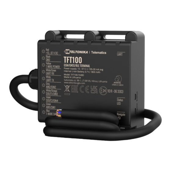
Teltonika Telematics TFT100 Quick Manual
2g tracker with high-voltage support for e-mobility & heavy machinery
Hide thumbs
Also See for Telematics TFT100:
- Quick manual (13 pages) ,
- How-to (4 pages) ,
- Manual (2 pages)

Related Manuals for Teltonika Telematics TFT100


Summary of Contents for Teltonika Telematics TFT100
- Page 1 TFT100 2G tracker with high-voltage support for e-mobility & heavy machinery Quick Manual v1.0...
-
Page 2: Table Of Contents
CONTENT Know your device ........................................3 UART Pinout .........................................4 CAN Pinout ...........................................5 RS232 Pinout ........................................6 RS485 Pinout ........................................7 Wiring scheme ........................................8 Set up your device ......................................9 PC Connection (Windows) ....................................10 How to install USB drivers (Windows) ................................10 Configuration........................................11 Quick SMS configuration .................................... -
Page 3: Know Your Device
KNOW YOUR DEVICE TOP VIEW (WITHOUT COVER) TOP VIEW TOP VIEW TOP VIEW (WITHOUT COVER) MICRO-SIM BATTERY SLOT SOCKET POWER CABLE NAVIGATE STATUS TFT100 GNSS ANTENNA ANTENNA MICRO-USB Quick Manual v1.0 // TFT100... -
Page 4: Uart Pinout
UART PINOUT PIN COLOR PIN NAME DESCRIPTION Power supply (+10...97 V +10...97 V DC VCC (10-97) V DC (+) DC). Black GND (-) Ground. Power supply pin for Dallas 1-WIRE POWER Yellow 1WIRE POWER 1-Wire devices. White/ UART-RX Input for data reception UART-RX through UART. -
Page 5: Can Pinout
CAN PINOUT PIN COLOR PIN NAME DESCRIPTION Power supply (+10...97 V +10...97 V DC VCC (10-97) V DC (+) DC). Black GND (-) Ground. Power supply pin for Dallas 1-WIRE POWER Yellow 1WIRE POWER 1-Wire devices. White/ CAN-H CAN-H CAN interface High. Green CAN-L White... -
Page 6: Rs232 Pinout
RS232 PINOUT PIN COLOR PIN NAME DESCRIPTION Power supply (+10...97 V +10...97 V DC VCC (10-97) V DC (+) DC). Black GND (-) Ground. Power supply pin for Dallas 1-WIRE POWER Yellow 1WIRE POWER 1-Wire devices. White/ RS232-IN RS232-IN Input wire for RS232. Green RS232-OUT White... -
Page 7: Rs485 Pinout
RS485 PINOUT PIN COLOR PIN NAME DESCRIPTION Power supply (+10...97 V +10...97 V DC VCC (10-97) V DC (+) DC). Black GND (-) Ground. Power supply pin for Dallas 1-WIRE POWER Yellow 1WIRE POWER 1-Wire devices. White/ RS485-B Input for data reception RS485-B through UART. -
Page 8: Wiring Scheme
WIRING SCHEME IF USING DOUT1 RS485 RS232 ALARM BUTTON BUZZER IF USING DIN2 BUFFERED BUFFERED IF USING DIN3 TRANSPARENT TRANSPARENT CONFIGURATION MODE MODE VIA PC VEHICLE CAN INTERFACE IBUTTON IF USING DIN4 IF USING DIN1 SUPER RFID SOCO POWER SUPPLY 10 - 97 V DC Quick Manual v1.0 // TFT100... -
Page 9: Set Up Your Device
SET UP YOUR DEVICE HOW TO INSERT MICRO-SIM CARD COVER REMOVAL MICRO-SIM CARD INSERT BATTERY CONNCETION Remove the bottom cover. Insert Micro-SIM card shown Connect the battery as shown to the with PIN request disabled or read device. Security info how to enter it later in Configurator. -
Page 10: Pc Connection (Windows)
Extract and run TeltonikaCOMDriver.exe. Click Next in driver installation window. In the following window click Install button. Setup will continue installing the driver and eventually the confirmation window will appear. Click Finish to complete the setup. https://wiki.teltonika-gps.com/images/d/d0/TeltonikaCOMDriver.zip Quick Manual v1.0 // TFT100... -
Page 11: Configuration
CONFIGURATION At first TFT100 device will have default factory settings set. These settings should be changed according to the user’s needs. Main configuration can be performed via Teltonika Configurator software. Get the latest Configurator version from here . Configurator operates on Microsoft Windows OS and uses prerequisite MS .NET Framework. Make sure you have the correct version installed. - Page 12 Data Acquisition – where data acquiring parameters can be configured. More details about TFT100 configuration using Configurator can be found in our Wiki wiki.teltonika-gps.com/view/TFT100_Status_info wiki.teltonika-gps.com/view/TFT100_Status_info#GNSS_Info wiki.teltonika-gps.com/view/TFT100_Status_info#GSM_Info wiki.teltonika-gps.com/view/TFT100_Status_info#I.2FO_Info wiki.teltonika-gps.com/view/TFT100_Status_info#Maintenance wiki.teltonika-gps.com/index.php?title=TFT100_GPRS_settings After connection to Configurator Status window will be wiki.teltonika-gps.com/index.php?title=TFT100_Data_acquisition_set-...
-
Page 13: Quick Sms Configuration
QUICK SMS CONFIGURATION Default configuration has optimal parameters present to ensure best performance of track quality and data usage. Quickly set up your device by sending this SMS command to it: « setparam 2001:APN;2002:APN_username;2003:APN_password;2004:Domain;2005:Port;2006:0» Note: Before SMS text, two space symbols should be inserted. GPRS SETTINGS: 2001 –... - Page 14 EVERY 120 SECOND 1 HOUR PASSES it is sent to the server while vehicle is If device has made a stationary record Time intervals and default I/O elements can be changed by using Teltonika Configurator https://wiki.teltonika-gps.com/view/TFT100_Firmware_and_configurator Quick Manual v1.0 // TFT100...
-
Page 15: Mounting Recommendations
MOUNTING RECOMMENDATIONS CONNECTING WIRES • Wires should be connected while the module is not plugged in. • Wires should be fastened to stable wires or other non-moving parts. Any heat emitting and/or moving objects should be kept away from the wires. •... -
Page 16: Basic Characteristics
**CAN with integrated 120 ohm resistor ***RS485 interface ****RS232 interface Blinking fast Device firmware is being flashed *****UART interface constantly MODULE Name Teltonika TM2500 STATUS LED INDICATIONS Technology 2G(GSM/GPRS)/GNSS/BLUETOOTH BEHAVIOUR MEANING GNSS Blinking every GNSS Teltonika TM2500 Normal mode... - Page 17 POWER CONSUMPTION Hot start < 1 s At 12V (Ultra Deep < 8 mA Sleep) Warm start < 25 s At 12V (Deep Sleep) < 12 mA Cold start < 35 s At 12V (Online Deep < 12 mA *Optional GNSS modes available with custom firmware development, Sleep) for more information contact your sales manager.
- Page 18 Storage temperature LED indication 2 status LED lights -20 °C to +45 °C (with battery) Micro-SIM, eSIM** Operating humidity 5% to 95% non-condensing Memory 128MB internal flash memory Ingress protection IP67 Rating *Depending on ordered TFT100 modification **eSIM is available with separate PCB assembly, for more information contact your sales manager Battery charge 0 °C to +45 °C...
- Page 19 Configuration and FOTA Web, Teltonika Configurator firmware update (USB, Bluetooth) Configuration, Events, Debug GPRS commands Configuration, Debug Time GNSS, NITZ, NTP Synchronization Accelerometer, External Power Ignition detection Voltage, DIN1, DIN3, DIN4, CAN* *Available for TFT100-TAIB0 and TFT100-TAIBA **Available for TFT100-TAIBB ***Available for TFT100-TAIBC and TFT100-TAIBD CERTIFICATION &...
-
Page 20: Safety Information
SAFETY INFORMATION This message contains information on how to operate Installation and/or handling during a lightning storm the device safely. By following these requirements and is prohibited. recommendations, you will avoid dangerous situations. Please read these instructions carefully and follow them strictly before operating the device! The device is susceptible to water and humidity. -
Page 21: Certification And Approvals
Full User‘s Manual version can be found mixed with general household waste. in our Wiki https://wiki.teltonika-gps.com/view/TFT100 CHECK ALL CERTIFICATES All newest certificates may be found in our Wiki https://wiki.teltonika-gps.com/view/TFT100_Certification_%26_Approvals Quick Manual v1.0 // TFT100... -
Page 22: Warranty
Warranty does not apply to any consequential damages. • Warranty is not applicable for supplementary product equipment (i. e. PSU, power cables, antennas) unless the accessory is defective on arrival. • More information on what is RMA wiki.teltonika-gps.com/view/RMA_guidelines Quick Manual v1.0 // TFT100...
Need help?
Do you have a question about the Telematics TFT100 and is the answer not in the manual?
Questions and answers