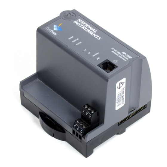
National Instruments FieldPoint FP-1600 User Manual
Network module
Hide thumbs
Also See for FieldPoint FP-1600:
- Operating instructions manual (9 pages) ,
- Quick start manual (21 pages)

Related Manuals for National Instruments FieldPoint FP-1600


Summary of Contents for National Instruments FieldPoint FP-1600
- Page 1 FP-1600 User Manual FieldPoint FP-1600 User Manual July 1999 Edition Part Number 322394A-01...
- Page 2 Switzerland 056 200 51 51, Taiwan 02 2377 1200, United Kingdom 01635 523545 For further support information, see the Technical Support Resources appendix. To comment on the documentation, send e-mail to techpubs@natinst.com. © Copyright 1999 National Instruments Corporation. All rights reserved.
- Page 3 The FieldPoint FP-1600 network module is warranted against defects in materials and workmanship for a period of one year from the date of shipment, as evidenced by receipts or other documentation. National Instruments will, at its option, repair or replace equipment that proves to be defective during the warranty period. This warranty includes parts and labor.
-
Page 4: Table Of Contents
Mount I/O Modules onto Terminal Bases ..............2-5 Connect Your FP-1600 to the Network .................2-6 Cabling...........................2-7 Connect Power to the FP-1600 ..................2-8 Calculating Power for a FieldPoint Bank............2-9 Power On the FP-1600....................2-10 Install the FieldPoint Software ..................2-10 © National Instruments Corporation FieldPoint FP-1600 User Manual... - Page 5 HotPnP During Power-Up ................4-4 HotPnP During Operation ................4-4 Inserting New I/O Modules .............. 4-5 Replacing I/O Modules..............4-5 Power-On Self Test (POST)..................4-6 Appendix A Resetting the FP-1600 Appendix B Troubleshooting Appendix C Specifications FieldPoint FP-1600 User Manual www.natinst.com...
- Page 6 FP-1600 Reset Switch ................A-2 Figure B-1. LEDs on the FP-1600 ................B-5 Tables Table 2-1. Ethernet Cable Wiring Connections............2-7 Table 4-1. Module Configuration Results After HotPnP Replacement....4-5 Table B-1. STATUS LED Flashes and Corresponding Error Conditions....B-6 © National Instruments Corporation FieldPoint FP-1600 User Manual...
-
Page 7: About This Manual
About This Manual This manual describes how to install and use the FieldPoint FP-1600 network module. How to Use This Manual Set Operating Instructions for Modules and Bases Installation Specifications FieldPoint Network Connection, User Manual Hardware Configuration, and Feature Set... -
Page 8: Conventions
Related Documentation The following documents contain information that you might find helpful as you read this manual: • Operating Instructions (for network module, terminal bases, and I/O modules) • FieldPoint software online help FieldPoint FP-1600 User Manual www.natinst.com... -
Page 9: Overview Of Fp-1600 Hardware And Fieldpoint Software
Overview of FP-1600 Hardware and FieldPoint Software This chapter provides an overview of the FieldPoint FP-1600 network module and FieldPoint software. FP-1600 Hardware Overview A FieldPoint system consists of at least one network module, at least one terminal base, and one or more I/O modules. -
Page 10: Fieldpoint Software Overview
I/O channels. Version 2.0 of the FieldPoint software runs on Windows 98, Windows 95, and Windows NT 4.0 and later, and includes the following components. • FieldPoint Explorer configuration utility • BridgeVIEW Server • LabVIEW VIs FieldPoint FP-1600 User Manual www.natinst.com... -
Page 11: Fieldpoint Explorer Configuration Utility
C function calls to communicate with I/O items configured in the FieldPoint Explorer. An instrument driver with a set of function panels and example programs is provided to accelerate your development process. © National Instruments Corporation FieldPoint FP-1600 User Manual... -
Page 12: Opc Server
The FieldPoint OPC server provides an interface to the I/O items configured in the FieldPoint Explorer and software packages that are capable of using OPC, including recent versions of Microsoft’s Visual Basic and Visual C/C++ programming environments, and other third-party software packages. FieldPoint FP-1600 User Manual www.natinst.com... -
Page 13: Hardware And Software Installation
Hardware and Software Installation This chapter describes how to mount your FieldPoint FP-1600 network module, connect the terminal bases, connect power to the FP-1600, connect the FP-1600 to an Ethernet network, and install your FieldPoint software. Mount the FP-1600 and Terminal Bases You can mount your FieldPoint system either to a DIN rail or directly on a panel. -
Page 14: Connecting Terminal Bases With Din Rail Mounting
Follow these steps to connect a terminal base to an FP-1600 network module using DIN rail mounting. Caution To avoid damaging the FP-1600 and the terminal bases, make sure that power is not applied to the FP-1600 while you install or remove terminal bases. FieldPoint FP-1600 User Manual www.natinst.com... -
Page 15: Removing The Fp-1600 And Terminal Bases From The Din Rail
Follow these steps to install the optional FieldPoint network panel mount accessory and mount the FP-1600 network module to a panel. You can order the panel mount accessory, part number 777609-01, from National Instruments. © National Instruments Corporation FieldPoint FP-1600 User Manual... -
Page 16: Connecting Terminal Bases With Panel Mounting
Drill pilot holes in the panel to mount the terminal bases. A drilling guide is provided with the network module panel mount accessory. Attach the terminal base to the FP-1600 by firmly mating the local bus connectors. FieldPoint FP-1600 User Manual www.natinst.com... -
Page 17: Removing The Fp-1600 And Terminal Bases From The Panel
Make sure the ejector button on the terminal base is pressed down in the unlocked position. Position the first module with its alignment slots aligned with the guide rails on the terminal base. © National Instruments Corporation FieldPoint FP-1600 User Manual... -
Page 18: Connect Your Fp-1600 To The Network
FP-1600 directly to a computer using an Ethernet crossover cable. Note Do not use a cable longer than 100 m. If you are using a 100 Mbps Ethernet, National Instruments recommends using a Category 5 shielded twisted-pair Ethernet cable. FieldPoint FP-1600 User Manual www.natinst.com... -
Page 19: Cabling
Connector 2 Connector 2 Connector 1 (Normal) (Crossover) white/orange white/orange white/green orange orange green white/green white/green white/orange blue blue blue white/blue white/blue white/blue green green orange white/brown white/brown white/brown brown brown brown © National Instruments Corporation FieldPoint FP-1600 User Manual... -
Page 20: Connect Power To The Fp-1600
The FP-1600 filters and regulates this supplied power and provides power for all the I/O modules in the bank. Therefore, you do not need to provide power separately to each FieldPoint I/O module in the bank. FieldPoint FP-1600 User Manual www.natinst.com... -
Page 21: Calculating Power For A Fieldpoint Bank
I/O modules. It does not include any power consumed by devices that you wire to the terminal bases. The operating instructions for each FieldPoint I/O module contain power consumption information. © National Instruments Corporation FieldPoint FP-1600 User Manual... -
Page 22: Power On The Fp-1600
If the setup does not launch automatically, select Start»Run from Windows, enter , where is the letter of your CD-ROM drive, and select OK. d :\setup The hardware and software installation is now complete. Proceed to Chapter 3, Hardware and Software Configuration. FieldPoint FP-1600 User Manual 2-10 www.natinst.com... -
Page 23: Hardware And Software Configuration
ToolTips, ScreenTips, and online help. ToolTips identify tool bar icons and most items on the screen. Rest your pointer over the element you are interested in, and its name appears, as shown in Figure 3-1. © National Instruments Corporation FieldPoint FP-1600 User Manual... -
Page 24: Figure 3-1. Tooltips Showing The Name Of An Item
Display ScreenTips by clicking on the question mark button in the title bar of the dialog box and then clicking on the item you want to know more about. The ScreenTip appears, as shown in Figure 3-2. FieldPoint FP-1600 User Manual www.natinst.com... -
Page 25: Configure Your Hardware With Fieldpoint Explorer
FieldPoint system is powered on and the I/O modules have their READY LEDs lit. From the Windows Start menu, select Programs»National Instruments FieldPoint»FieldPoint Explorer. The FieldPoint Explorer appears. Figure 3-3 shows the parts of the FieldPoint Explorer window. © National Instruments Corporation FieldPoint FP-1600 User Manual... -
Page 26: Figure 3-3. Fieldpoint Explorer Window
+ sign next to IA Server with OPC in the DNH frame to expand the view. Then, right-click on FieldPoint and select Add a comm resource to this server. The Comm Resource Configuration dialog box appears, as shown in Figure 3-4. FieldPoint FP-1600 User Manual www.natinst.com... -
Page 27: Figure 3-4. Comm Resource Configuration Dialog Box
IP Address field, then proceed to the section Find and Configure Devices. If you do not know the address, click on Browse to locate the device. The Network Devices window appears, as shown in Figure 3-5. © National Instruments Corporation FieldPoint FP-1600 User Manual... -
Page 28: Ethernet Parameters
IP address, refer to the next section, Choose an IP Address. • Subnet mask—A code that helps the network device determine whether another device is on the same network or a different network. is the most common subnet mask. 255.255.255.0 FieldPoint FP-1600 User Manual www.natinst.com... -
Page 29: Choose An Ip Address
• Time Server IP—The IP address of a networked computer that runs the National Instruments Time Service. This is usually the IP address of one of the computers that you run FieldPoint software on. IP address, Subnet mask, and Time Server IP are required parameters. If... - Page 30 Hardware and Software Configuration The Time Server IP is the address of the computer where you have installed the National Instruments Time Service. Time Service is installed along with the FieldPoint software and with Lookout 4.0 and will run automatically.
-
Page 31: Set Fp-1600 Properties
Suggest Values might provide settings that do not work with your network. Note When the FP-1600 reappears in the Network Devices window with its own IP address, it is ready to use. Click on the IP Address, then click on Select. © National Instruments Corporation FieldPoint FP-1600 User Manual... -
Page 32: Find And Configure Devices
Right-click on the device name, and select Edit this device from the pop-up menu. Click on the Channel Configuration button to bring up the Channel Configuration dialog box, shown in Figure 3-7. In this example, an FP-TC-120 thermocouple module is selected. FieldPoint FP-1600 User Manual 3-10 www.natinst.com... -
Page 33: Figure 3-7. Channel Configuration Dialog Box
Click on the OK button when you are finished, or click on the Apply button to save the changes and continue to configure channels. When you click on OK or Apply, the changes are immediately sent to the device. © National Instruments Corporation 3-11 FieldPoint FP-1600 User Manual... - Page 34 To edit the device configuration of the FP-1600 network module, right-click on the network module entry in the DNH frame, then select Edit this device from the pop-up menu. Make sure that the factory configuration checkbox is not checked. FieldPoint FP-1600 User Manual 3-12 www.natinst.com...
-
Page 35: Use The Fp-1600 With Other Applications
FieldPoint Explorer to export the current configuration file that you saved to BridgeVIEW’s active CCDB. (If BridgeVIEW is not an option on your FieldPoint Explorer’s menu bar, make sure that you have installed the FieldPoint software after installing BridgeVIEW.) © National Instruments Corporation 3-13 FieldPoint FP-1600 User Manual... - Page 36 Tag Configuration Editor and save the changes to the configuration file. You can now access the FieldPoint I/O Items by reading or writing these tags as you would any other tag in BridgeVIEW. FieldPoint FP-1600 User Manual 3-14 www.natinst.com...
-
Page 37: Lookout
Chapter 3 Hardware and Software Configuration Lookout The FP-1600 was designed to integrate easily with National Instruments Lookout 4.0. You can access the FP-1600 the same way you would access another desktop computer running Lookout 4.0. You can access the channel data, ranges, attributes, and commands from Lookout, as well as several control variables, such as Reset and Snapshot. -
Page 38: Labview Vis
LabVIEW VIs. The FieldPoint LabVIEW Help document is in the same program group on your Windows taskbar as the FieldPoint Explorer program. This help document explains how to use the FieldPoint VIs. FieldPoint FP-1600 User Manual 3-16 www.natinst.com... - Page 39 Note This example reads the value of an I/O Item value from the FieldPoint device. To write to an Output Item, use FP Write instead of FP Advise (or FP Read). © National Instruments Corporation 3-17 FieldPoint FP-1600 User Manual...
-
Page 40: Labwindows/Cvi Functions
To use an alternate compatibility, copy the supplied file from the compiler .obj folder (for instance, ) with which you /CVI/FieldPoint/borland/FieldPoint.obj would like compatibility to the subdirectory of the CVI directory. /FieldPoint FieldPoint FP-1600 User Manual 3-18 www.natinst.com... -
Page 41: Fieldpoint Opc Server
IDs of the I/O Items directly. The naming convention of the FieldPoint Item IDs is Comm resource name\Device Name\I/O Item name where the Comm resource name, Device name, and I/O Item name are © National Instruments Corporation 3-19 FieldPoint FP-1600 User Manual... - Page 42 “Bad, non-specific” along with an error code. Some OPC clients that do not support this “GetErrorString” method might still provide a way for you to manually look up the FieldPoint message corresponding to the error code using the method. FieldPoint FP-1600 User Manual 3-20 www.natinst.com...
-
Page 43: Feature Set Description
Each bank has only one watchdog timeout value that is common for all the modules in that bank. In addition, the current watchdog timeout value is not stored when you store the SnapShot. © National Instruments Corporation FieldPoint FP-1600 User Manual... -
Page 44: Snapshot Feature
To make incremental changes in the stored SnapShot information, use the features described in the next section, Programmable Power-Up State. The current watchdog timeout value for the FieldPoint bank is not saved when you Note store the SnapShot. FieldPoint FP-1600 User Manual www.natinst.com... -
Page 45: Programmable Power-Up State
Watchdog timer enabled (or disabled) status of each module. Refer to the Network Watchdog Timer section in this chapter for more information. • Power-up watchdog timeout value for the FieldPoint bank. • The turn-around delay for each module. © National Instruments Corporation FieldPoint FP-1600 User Manual... -
Page 46: Hotpnp (Hot Plug And Play)
As soon as the FP-1600 configures the new or replacement I/O module through the HotPnP service, that I/O module becomes automatically accessible on the network. FieldPoint FP-1600 User Manual www.natinst.com... -
Page 47: Inserting New I/O Modules
Replacement Module Feature Module Configuration After HotPnP Enabled/Disabled Compatible with the removed Same as the configuration of the module removed module Disabled Incompatible with the removed Factory default configuration of module replacement module © National Instruments Corporation FieldPoint FP-1600 User Manual... -
Page 48: Power-On Self Test (Post)
The FP-1600 indicates POST failure through the POWER and STATUS LEDs. Refer to the section LED Indicators in Appendix B, Troubleshooting, for more information. FieldPoint FP-1600 User Manual www.natinst.com... -
Page 49: Appendix A Resetting The Fp-1600
Power down the FP-1600 and remove it from the bank. Locate the slot on the bottom of the FP-1600 just above the label. Inside the slot, find the red reset switch, shown in Figure A-1. © National Instruments Corporation FieldPoint FP-1600 User Manual... -
Page 50: Figure A-1. Fp-1600 Reset Switch
The following tips should help you avoid having to manually reset the module: • When you configure the FP-1600, wait for the message . If this message does module’s configuration was confirmed not appear, the FP-1600 might not be properly configured. FieldPoint FP-1600 User Manual www.natinst.com... - Page 51 You must reconfigure the module before you can use it again. Note You should not need to select Reset Module unless you want to reset the device and put it in storage. © National Instruments Corporation FieldPoint FP-1600 User Manual...
-
Page 52: Appendix B Troubleshooting
The file should include the following lines: 127.0.0.1 localhost 12.34.56.78 fp where is the hostname of the FP-1600 and is the 12.34.56.78 IP address of the FP-1600. © National Instruments Corporation FieldPoint FP-1600 User Manual... - Page 53 FP-1600 whose settings you would like to view, and click on Device Properties. When you are done editing/viewing the settings, click on OK. Click on Cancel to discard any changes you have made. FieldPoint FP-1600 User Manual www.natinst.com...
- Page 54 • The module may have been configured on another network and then moved to the current network. Refer to Appendix A, Resetting the FP-1600, for instructions on resetting the FP-1600. © National Instruments Corporation FieldPoint FP-1600 User Manual...
- Page 55 Instruments Time Service is correctly configured for the FP-1600. • Make sure that National Instruments Time Service was installed on the desired machine and is running. If Time Service is installed but is not running, restart it. –...
-
Page 56: Figure B-1. Leds On The Fp-1600
Caution Do not power down the FP-1600 while the PROCESS LED is lit. The green TX LED is lit when the FP-1600 transmits data over the Ethernet. © National Instruments Corporation FieldPoint FP-1600 User Manual... - Page 57 Configure Your Hardware with FieldPoint Explorer in Chapter 3, Hardware and Software Configuration. 4 (or more) The FP-1600 has detected an unrecoverable error. Contact National Instruments for more information of finding the cause of this error. FieldPoint FP-1600 User Manual www.natinst.com...
-
Page 58: Appendix C Specifications
Maximum terminal bases per bank ..9 Maximum number of banks ....determined by network topology Environment Operating temperature......–20 to +55 °C Storage temperature ....... –55 to +85 °C Relative humidity ........5% to 90% noncondensing © National Instruments Corporation FieldPoint FP-1600 User Manual... - Page 59 Appendix C Specifications Compliance Electrical safety ........designed to meet IEC 1010 EMI emissions/immunity .......CISPR 11 FieldPoint FP-1600 User Manual www.natinst.com...
-
Page 60: Technical Support Resources
Technical Support Resources This appendix describes the comprehensive resources available to you in the Technical Support section of the National Instruments Web site and provides technical support telephone numbers for you to use if you have trouble connecting to our Web site or if you do not have internet access. - Page 61 If you have trouble connecting to our Web site, please contact your local National Instruments office or the source from which you purchased your National Instruments product(s) to obtain support. For telephone support in the United States, dial 512 795 8248. For...
-
Page 62: Glossary
International Special Committee On Radio Interference domain name system electronic data sheet electromagnetic interference file transfer protocol HotPnP Hot Plug and Play International Electrotechnical Commission input/output Light-emitting diode meter OLE for Process Control © National Instruments Corporation FieldPoint FP-1600 User Manual... - Page 63 Glossary POST power-on self test point-to-point protocol SLIP serial line internet protocol Volts Volts direct current FieldPoint FP-1600 User Manual www.natinst.com...
- Page 64 FP-1600 to network, 2-6 to 2-7 connecting terminal bases FieldPoint Explorer Configuration Utility, DIN rail mount, 2-2 to 2-3 3-3 to 3-13 panel mount, 2-4 to 2-5 Channel Configuration dialog box (figure), 3-11 © National Instruments Corporation FieldPoint FP-1600 User Manual...
- Page 65 HotPnP (Hot Plug and Play), 4-4 to 4-6 under Windows 95/98, B-1 installation under Windows NT 4.0, B-1 cabling, 2-7 to 2-8 HotPnP (Hot Plug and Play), 4-4 to 4-6 connecting FP-1600 to network, inserting new I/O modules, 4-5 2-6 to 2-7 FieldPoint FP-1600 User Manual www.natinst.com...
- Page 66 2-3 to 2-4 I/O modules removing FP-1600 and terminal inserting new, 4-5 bases, 2-5 mounting onto terminal bases, 2-5 to 2-6 replacing, 4-5 IP addresses. See Ethernet network. ipcfg utility, 3-8 © National Instruments Corporation FieldPoint FP-1600 User Manual...
- Page 67 Index resetting FP-1600 to factory configuration, A-1 to A-3 National Instruments Web support, D-1 to D-2 RX LED, B-6 Network Device Configurator, B-2 networks. See also Ethernet network. specifications, C-1 watchdog timer, 4-1 ScreenTips, 3-2 to 3-3 serial number information (note), 2-1 SnapShot feature, 4-2 to 4-3 software.
- Page 68 Index watchdog timer, 4-1 Web support from National Instruments, D-1 to D-2 online problem-solving and diagnostic resources, D-1 software-related resources, D-2 winipcfg utility, 3-8 Worldwide technical support, D-2 © National Instruments Corporation FieldPoint FP-1600 User Manual...
Need help?
Do you have a question about the FieldPoint FP-1600 and is the answer not in the manual?
Questions and answers