Advertisement
Quick Links
OPERATING INSTRUCTIONS
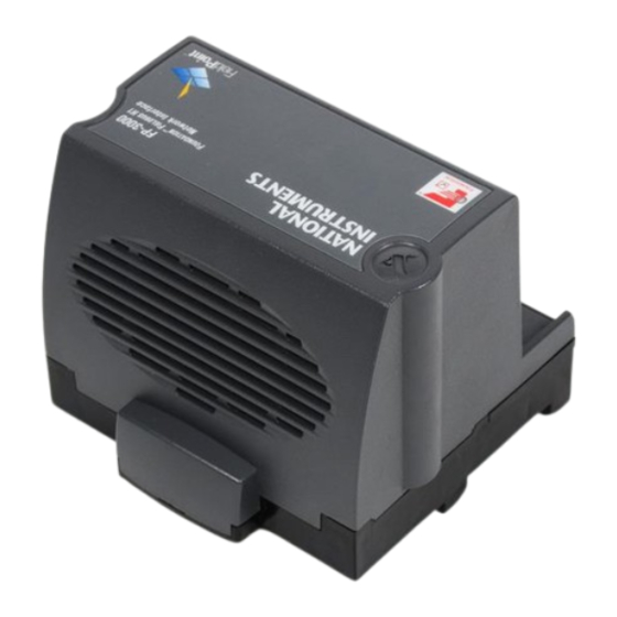
FP-3000
FieldPoint Network Module
Features
•
FOUNDATION Fieldbus H1 interface to control network
•
Runs on 11 to 30 VDC power
•
Built-in high efficiency power supply powers I/O modules
•
–40° to +60° C operation
Kit Contents
•
FP-3000 network module
•
Bag of accessories:
–
Protective connector cover
–
Two DIN rail stops
–
Device Description diskette
Optional Equipment
You can order the following optional equipment from National
Instruments:
•
Panel mount accessory, part #777609-01
•
Terminal bases and I/O modules. You can view a complete list
of terminal bases and I/O modules in the National Instruments
online catalog at
•
Cables
•
24 VDC power supply
FieldPoint ™ is a trademark of National Instruments Corporation. Product and company names
mentioned herein are trademarks or trade names of their respective companies.
322170A-01
© Copyright 1999 National Instruments Corp. All rights reserved. January 1999
www.natinst.com
Advertisement

Related Manuals for National Instruments FieldPoint FP-3000


Summary of Contents for National Instruments FieldPoint FP-3000
- Page 1 Cables • 24 VDC power supply FieldPoint ™ is a trademark of National Instruments Corporation. Product and company names mentioned herein are trademarks or trade names of their respective companies. 322170A-01 © Copyright 1999 National Instruments Corp. All rights reserved. January 1999...
- Page 2 Figure 1. DIN Rail Clip 2. Hook the lip on the rear of the FP-3000 onto the top of a 35 mm DIN rail and press the FP-3000 down onto the DIN rail, as shown in Figure 2. Operating Instructions © National Instruments Corp.
- Page 3 The FP-3000 is shipped with a protective cover in the bag of accessories. Place the protective cover over the local bus connector of the last terminal base in the bank. Figure 3 shows an installed FP-3000 network module. © National Instruments Corp. Operating Instructions...
- Page 4 Connect the FP-3000 to a Fieldbus network using the 9-position DSub connector on the FP-3000. The pinout of the DSub connector is shown in Figure 4. NC = No Connection Figure 4. Dsub Connector Pinout Operating Instructions © National Instruments Corp.
- Page 5 V and C pair. The right V and C pair provides a convenient means of connecting power to the V and C terminals of a terminal base. Figure 5 shows this optional connection. © National Instruments Corp. Operating Instructions...
-
Page 6: Specifications
Immunity ........EN 50082-1:1994 Emissions ........EN 55011:1991 Group I Class A at 10 meters Mechanical Dimensions Figure 6 shows the mechanical dimensions of the FP-3000. 4.19 [106.4] 4.31 [109.5] 3.58 [90.9] Figure 6. Mechanical Dimensions Operating Instructions © National Instruments Corp.
Need help?
Do you have a question about the FieldPoint FP-3000 and is the answer not in the manual?
Questions and answers