National Instruments NI-9375 Getting Started
Hide thumbs
Also See for NI-9375:
- Getting started manual (21 pages) ,
- Getting started manual (23 pages) ,
- Getting started (11 pages)
Table of Contents
Advertisement
Quick Links
Advertisement
Table of Contents

Subscribe to Our Youtube Channel
Related Manuals for National Instruments NI-9375


Summary of Contents for National Instruments NI-9375
- Page 1 NI-9375 Getting Started 2022-07-06...
-
Page 2: Table Of Contents
NI-9375 Getting Started Contents Overview..............3 Safety Guidelines. -
Page 3: Overview
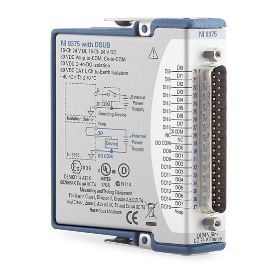
NI-9375 Getting Started Overview This document explains how to connect to the NI 9375. In this document, the NI 9375 with spring terminal and the NI 9375 with DSUB are referred to inclusively as the NI 9375. Note Before you begin, read the NI 9375 Safety, Environmental, and Regulatory Information document on ni.com/manuals... -
Page 4: Safety Guidelines For Hazardous Locations
NI-9375 Getting Started Isolation DI bank-to-DO bank 60 V DC maximum Channel-to-Channel No isolation between channels Channel-to-earth ground Continuous 60 V DC, Measurement Category I Withstand 1,000 V RMS, verified by a 5 s dielectric withstand test Safety Guidelines for Hazardous Locations The NI 9375 is suitable for use in Class I, Division 2, Groups A, B, C, D, T4 hazardous locations;... -
Page 5: Electromagnetic Compatibility Guidelines
NI-9375 Getting Started Special Conditions for Hazardous Locations Use in Europe and Internationally The NI 9375 has been evaluated as Ex nA IIC T4 Gc equipment under DEMKO 07ATEX 0626664X and is IECEx UL 14.0089X certified. Each NI 9375 is marked II 3G and is suitable for use in Zone 2 hazardous locations, in ambient temperatures of -40 °C ≤... -
Page 6: Special Conditions For Marine Applications
Furthermore, any changes or modifications to the product not expressly approved by National Instruments could void your authority to operate it under your local regulatory rules. Special Conditions for Marine Applications Some products are approved for marine (shipboard) applications. -
Page 7: Ni 9375 Pinout
NI-9375 Getting Started NI 9375 Pinout DI10 DI11 DI10 DI12 DI11 DI13 DI12 DI13 DI14 DI14 DI15 DI15 DI COM DI COM DO COM DO10 DO10 DO11 DO11 DO12 DO12 DO13 DO13 DO14 DO14 DO15 DO15 V sup DO COM... -
Page 8: Connecting Digital Devices
NI-9375 Getting Started The NI 9375 channel registers as ON when the sourcing-output device drives enough current or applies enough voltage to DI. If no device is connected to DI, the channel registers as OFF. Connecting Digital Devices You can connect a variety of industrial devices, such as solenoids, motors, actuators, relays, and lamps to the NI 9375. -
Page 9: Protecting The Digital Outputs From Flyback Voltages
NI-9375 Getting Started Protecting the Digital Outputs from Flyback Voltages If the channel is switching an inductive or energy-storing device such as a solenoid, motor, or relay, and the device does not have flyback protection, install an external flyback diode. -
Page 10: High-Vibration Application Connections
NI-9375 Getting Started 1. Insert the screwdriver into a spring clamp activation slot to open the corresponding connector terminal. 2. Press a wire into the open connector terminal. 3. Remove the screwdriver from the activation slot to clamp the wire into place. -
Page 11: Ni Services
NI product. Product registration facilitates technical support and ensures that you receive important information updates from NI corporate headquarters is located at 11500 N Mopac Expwy, Austin, TX, 78759-3504, USA. © National Instruments © 2022 National Instruments Corporation.
Need help?
Do you have a question about the NI-9375 and is the answer not in the manual?
Questions and answers