Table of Contents
Advertisement
Quick Links
INSTALLATION GUIDE
NI TB-2709
PXI Terminal Block for S Series Devices
Introduction
This installation guide describes how to install and connect signals to the
NI TB-2709 terminal block for use with PXI-6123/6133 S Series devices.
The TB-2709 can also be used with the PXI-6122/6132 devices to access
the first four AI channels.
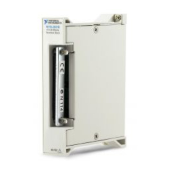
The TB-2709 is a terminal block assembly consisting of nine SMB
connectors and a 14-pin I/O connector. The terminal block assembly
connects directly to the front panel of National Instruments PXI-6122,
PXI-6123, PXI-6132, and PXI-6133 devices, eliminating the need for an
external cable.
1
1 Access Door to Configuration Switches
2 14-Pin I/O Connector (Digital Signals)
2
3 SMB Connectors (Analog Signals)
Figure 1. TB-2709 Device View
0
A I
1
A I
2
A I
3
A I
4
A I
3
5
A I
6
A I
7
A I
A I
T
A R
S T
I G
T R
Advertisement
Table of Contents

Summary of Contents for National Instruments PXI Terminal Block NI TB-2709
-
Page 1: Installation Guide
The TB-2709 is a terminal block assembly consisting of nine SMB connectors and a 14-pin I/O connector. The terminal block assembly connects directly to the front panel of National Instruments PXI-6122, PXI-6123, PXI-6132, and PXI-6133 devices, eliminating the need for an external cable. -
Page 2: What You Need To Get Started
If the device is damaged, turn the device off and do not use it until service-trained personnel can check its safety. If necessary, return the device to National Instruments for service and repair to ensure that its safety is not compromised. -
Page 3: Installation
Do not substitute parts or modify equipment. Because of the danger of introducing additional hazards, do not install unauthorized parts or modify the device. Return the device to National Instruments for service and repair to ensure that its safety features are not compromised. -
Page 4: Signal Descriptions
To connect the terminal block to the PXI module I/O connector, refer to Figure 2 as you complete the following steps: Caution Do not force the terminal block when inserting it into or removing it from the PXI module I/O connector. Signal Descriptions Figure 3 shows the front panel of the TB-2709, and Figure 4 shows the TB-2709 block diagram. - Page 5 ON (floating source) switch position. In the floating source switch position, the amplifier negative terminal connects to ground through a 5 kΩ resistor in parallel with a 0.1 shows the TB-2709 switch configuration options. © National Instruments Corporation Front Panel SMB Connectors 5 kΩ...
-
Page 6: Cabling Options
TB-2709 Switch Configuration Floating Source Signal Source – Ground- Referenced Source Signal Source – Measuring Ground-Referenced Signals It is possible to set the switch on the TB-2709 to either the floating or ground-referenced source position to measure ground-referenced signals. However, for best results, use the OFF (ground-referenced source) switch position to avoid ground loops. - Page 7 Figure 5 and Table 3 list the pin assignments and wiring information necessary for connecting the TB-2709 to DIO signals. Pin 7 Pin 1 © National Instruments Corporation CTR 0 OUT P0.3 Pin 14 P0.2 P0.1...
-
Page 8: Specifications
Do not apply an input voltage greater than 42 V voltages greater than 42 V to it, including the host computer. Overvoltage can also cause an electric shock hazard for the operator. National Instruments is not liable for damage or injury resulting from such misuse. NI TB-2709 Installation Guide Table 3. -
Page 9: Shock And Vibration
Storage temperature ... –20 to 70 °C Relative humidity ... 10 to 90% noncondensing Pollution Degree ... 2 © National Instruments Corporation Height... 10.7 × 8.6 × 2.0 cm Weight... 144.6 g (5.1 oz) 68-position SCSI-II type ... 1, female SMB jacks... -
Page 10: Waste Electrical And Electronic Equipment (Weee)
Waste Electrical and Electronic Equipment (WEEE) At the end of their life cycle, all products must be sent to a WEEE recycling EU Customers center. For more information about WEEE recycling centers and National Instruments WEEE initiatives, visit Where to Go for Support The National Instruments Web site is your complete resource for technical support. - Page 11 South Africa 27 0 11 805 8197, Spain 34 91 640 0085, Sweden 46 (0) 8 587 895 00, Switzerland 41 56 2005151, Taiwan 886 02 2377 2222, Thailand 662 278 6777, Turkey 90 212 279 3031, United Kingdom 44 (0) 1635 523545 © National Instruments Corporation NI TB-2709 Installation Guide...
- Page 12 Instruments trademarks. Other product and company names mentioned herein are trademarks or trade names of their respective companies. For patents covering National Instruments products, refer to the appropriate location: Help»Patents in your software, the patents.txt file on your CD, or ni.com/patents.


Need help?
Do you have a question about the PXI Terminal Block NI TB-2709 and is the answer not in the manual?
Questions and answers