
Subscribe to Our Youtube Channel
Related Manuals for Festo CPX-MMI-1


Summary of Contents for Festo CPX-MMI-1
- Page 1 Universal handheld Electronics manual Universal handheld type CPX−MMI−1 Commissioning and diagnosing CPX terminals Manual 534 825 en 0305NH [668 828]...
- Page 3 ....... . . 534 825 E (Festo AG & Co. KG, D 73726 Esslingen, Federal Republic of Germany, 2003) Internet: http://www.festo.com...
- Page 4 Contents and general instructions Festo P.BE−CPX−MM I−1−EN en 0305NH...
-
Page 5: Table Of Contents
......... 3−5 Festo P.BE−CPX−MM I−1−EN en 0305NH... - Page 6 ........4−55 4.9.2 Download parameters into the device ..... . . 4−57 Festo P.BE−CPX−MM I−1−EN en 0305NH...
- Page 7 ............C−3 Festo P.BE−CPX−MM I−1−EN en 0305NH...
-
Page 8: Designated Use
The hand control unit type CPX−MMI−1, called the handheld in the following, has been designed for commissioning and diag nosing Festo products. With the handheld, device states and faults can be visualized and, if necessary, settings for com missioning and fault finding can be undertaken. -
Page 9: Safety Instructions
Start without existing field bus connection, the Fail−safe status (field bus communication fault) will become active. Note that all outputs will then assume the signal status · defined by Fail safe (pre−setting: reset all outputs). Festo P.BE−CPX−MM I−1−EN en 0305NH... -
Page 10: Target Group
Service Please consult your local Festo repair service if you have any technical problems. VIII Festo P.BE−CPX−MM I−1−EN en 0305NH... -
Page 11: Important User Instructions
This means that failure to observe this instruction may result in damage to property. The following pictogram marks passages in the text which describe activities with electrostatically sensitive compo nents. Electrostatically sensitive components may be damaged if they are not handled correctly. Festo P.BE−CPX−MM I−1−EN en 0305NH... - Page 12 Accessories: Information on necessary or sensible accessories for the Festo product. Environment: Information on environment−friendly use of Festo products. Text markings The bullet indicates activities which may be carried out in · any order. 1. Figures denote activities which must be carried out in the numerical order specified.
-
Page 13: Notes On The Use Of This Manual
: enable [disable] : disable Translations of general operating functions can be found in this manual. Translations of parameters and data of the de vice used can be found in the documentation for the relevant device. Festo P.BE−CPX−MM I−1−EN en 0305NH... - Page 14 CPX−MMI−1. Further information on using the handheld in conjunction with the connected device or module can be found in the docu mentation for the relevant device or module. Festo P.BE−CPX−MM I−1−EN en 0305NH...
-
Page 15: Manuals On The Cpx Terminal
MPA pneumatics" sioning MPA pneumatics (type 32) Type P.BE−MPA−... Valve terminals with Information on fitting, installing and commis Midi/Maxi pneumatics" sioning Midi/Maxi pneumatics (type 03) type P.BE−Midi/ Maxi−03−... Table. 0/1: Manuals on the CPX terminal XIII Festo P.BE−CPX−MM I−1−EN en 0305NH... -
Page 16: Terms And Abbreviations Used With The Cpx Terminal
Idle status. If the device is in the Idle status, the signal states will be influenced directly. This parameter is only relevant for certain field bus protocols. I/Os Inputs and outputs Festo P.BE−CPX−MM I−1−EN en 0305NH... - Page 17 PLC/IPC Programmable logic controller/industrial PC Pneumatic interface The pneumatic interface is the interface between the modular electrical peripherals and the pneumatics. Table. 0/2: Product−specific terms and abbreviations Festo P.BE−CPX−MM I−1−EN en 0305NH...
-
Page 18: System Summary
System summary Chapter 1 1−1 Festo P.BE−CPX−MM I−1−EN en 0305NH... - Page 19 ........1−14 1−2 Festo P.BE−CPX−MM I−1−EN en 0305NH...
- Page 20 This chapter provides an overview of the structure, compo nents and method of operation of the handheld. Further information Detailed information on the device used can be found in the documentation for the relevant device. 1−3 Festo P.BE−CPX−MM I−1−EN en 0305NH...
-
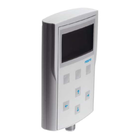
Page 21: Structure And Button Functions Of The Handheld
The handheld is operated with 7 touch−sensitive buttons with which all functions can be accessed by menu. LCD display Type plate on the rear Touch−sensitive buttons Connection for device Fig. 1/1: Overview of system 1−4 Festo P.BE−CPX−MM I−1−EN en 0305NH... - Page 22 The arrow buttons are marked with arrows and are situated under the function buttons. Arrow Description button Increase/reduce number value Select menu Set signal states Select signal Select figure or entry position Switch to next module Tab. 1/1: Arrow buttons 1−5 Festo P.BE−CPX−MM I−1−EN en 0305NH...
- Page 23 Abort current procedure OK" Confirm Select marked menu function Confirm entry Set" Transfer set value to the CPX ter minal Accept signal status/value Yes" Confirm current procedure Tab. 1/2: Possible functions of the function buttons 1−6 Festo P.BE−CPX−MM I−1−EN en 0305NH...
-
Page 24: The Starting Picture And Loading Procedure
Pictogram for Service worldwide" from Festo Fig. 1/3: Starting picture Handheld connected for If the handheld is connected to a device for the first time, the first time the necessary information about the device (e.g. - Page 25 All texts on the display appear in English. Translations of general operating functions can be found in this manual. Translations of parameters and data of the rel evant device can be found in the documentation for the de vice. 1−8 Festo P.BE−CPX−MM I−1−EN en 0305NH...
-
Page 26: Composition Of A Display Representation
If the function button <>" is shown in the bottom line, the visible section of the display area can be shifted horizontally to the right when the button is held pressed down (see Fig. 1/6). Tab. 1/3: Description of the display elements 1−9 Festo P.BE−CPX−MM I−1−EN en 0305NH... - Page 27 Function for shifting the visible section Visible section shifted to the right Arrow for identifying further characters at the end or beginning of a line. Description of the display area Fig. 1/6: Shift display representation horizontally (example) 1−10 Festo P.BE−CPX−MM I−1−EN en 0305NH...
-
Page 28: Composition And Functions Of The Main Menu (Example)
Module data (MD) Monitoring/Forcing (M) Diagnostics (D) 1: Module submenu Parameters (P) (e.g. 1: 4DI input module) Fail safe (F) Module data (MD) etc. Fig. 1/7: Composition of the main menu (example of a CPX terminal) 1−11 Festo P.BE−CPX−MM I−1−EN en 0305NH... - Page 29 With the aid of the module identifier and the module position you can find the menu command of the desired module submenu. In the module submenu you can quickly find all data and parameters of the relevant module. 1−12 Festo P.BE−CPX−MM I−1−EN en 0305NH...
- Page 30 2) operating mode Remote Controller (RC) or Remote I/O (RIO) 3) Further modules in preparation Tab. 1/4: Module identifiers of CPX modules (example) Detailed information on parametrizing a module can be found in the manual for the relevant module. 1−13 Festo P.BE−CPX−MM I−1−EN en 0305NH...
-
Page 31: Moving In The Menu System
Additional navigation possibility within Press the module submenu Switch to next module Switch to previous module You can switch, e.g. from a module submenu to the next mod ule submenu (see Fig. 1/9). 1−14 Festo P.BE−CPX−MM I−1−EN en 0305NH... - Page 32 Main menu (example CPX terminal) Module submenu (depends on the configuration) System submenu (here CPX terminal) An arrow marks the additional navigation possibility Fig. 1/9: Moving in the menu system (example of a CPX terminal) 1−15 Festo P.BE−CPX−MM I−1−EN en 0305NH...
- Page 33 __________________ __________________ Back <−> Back <−> Back <−> Module number Command identifier (D for Diagnostics) Module identifier Arrow buttons for switching further Fig. 1/10: Moving in the menu system (example of a CPX terminal) 1−16 Festo P.BE−CPX−MM I−1−EN en 0305NH...
-
Page 34: Fitting
Fitting Chapter 2 2−1 Festo P.BE−CPX−MM I−1−EN en 0305NH... - Page 35 ........2−9 2.1.4 Using the support as a hanging device ..... . 2−11 2−2 Festo P.BE−CPX−MM I−1−EN en 0305NH...
-
Page 36: Fitting
2. Fitting Contents of this chapter This chapter describes how to fit the handheld and the hand held supports. Further information Observe the following: the fitting instructions supplied with the product 2−3 Festo P.BE−CPX−MM I−1−EN en 0305NH... -
Page 37: Fitting The Handheld
The support is already prepared at the factory for fitting onto either a wall or a hat rail. When turned 180 ° the support en ables the handheld to be hung at a suitable location for a brief period (see section 2.1.4). 2−4 Festo P.BE−CPX−MM I−1−EN en 0305NH... -
Page 38: Placing The Handheld In The Support Or Removing It
If you wish to use the sup port for fitting onto a wall or hat rail, the bracket must face downwards (see also Fig. 2/2). 2−5 Festo P.BE−CPX−MM I−1−EN en 0305NH... - Page 39 2. Push the handheld down as far as possible. 3. Check to see if the lower edge of the handheld is flush with the support and that the handheld is seated correctly in the support. 2−6 Festo P.BE−CPX−MM I−1−EN en 0305NH...
- Page 40 Removing the handheld The handheld can be removed from the support with a gentle push. Fig. 2/3: Removing the handheld (here with wall or hat rail fitting) 2−7 Festo P.BE−CPX−MM I−1−EN en 0305NH...
-
Page 41: Fitting Onto A Wall
Fig. 2/4: Dimensions in [mm] Please note Make sure that there is sufficient space for connecting the cable and for inserting the handheld. Tighten the screws with max. 0.6 Nm. 2−8 Festo P.BE−CPX−MM I−1−EN en 0305NH... -
Page 42: Fitting Onto A Hat Rail
3. Secure the support with the clamping element (5) so that it cannot tilt or slide down. In order to do this turn the locking screw in a clockwise direction (see also following diagram). 2−9 Festo P.BE−CPX−MM I−1−EN en 0305NH... - Page 43 Fig. 2/6: Rear view: Fitting onto a hat rail Dismantling Dismantle the support as follows: 1. Remove the clamping element. In order to do this, turn the locking screw in an anti−clockwise direction. 2. Remove the support. 2−10 Festo P.BE−CPX−MM I−1−EN en 0305NH...
-
Page 44: Using The Support As A Hanging Device
If necessary, you can hang the cable in the semi−circular opening. Fastening hooks Opening for hanging the cable Fig. 2/7: Using the support as a hanging device 2−11 Festo P.BE−CPX−MM I−1−EN en 0305NH... - Page 45 2. Fitting 2−12 Festo P.BE−CPX−MM I−1−EN en 0305NH...
-
Page 46: Installation
Installation Chapter 3 3−1 Festo P.BE−CPX−MM I−1−EN en 0305NH... - Page 47 ......... 3−5 3−2 Festo P.BE−CPX−MM I−1−EN en 0305NH...
- Page 48 (e.g. menu commands and display texts) will be loaded from the connected device into Informationen on this can be the memory of the handheld. found in section 1.2. 3−3 Festo P.BE−CPX−MM I−1−EN en 0305NH...
-
Page 49: General Installation Instructions
The power supply for the handheld is provided by the connected device. Instructions on the power supply for the device can be found in the documentation for the relevant device. 3−4 Festo P.BE−CPX−MM I−1−EN en 0305NH... -
Page 50: Connecting The Handheld
Service interfaces with plastic threads Insert the plug of the cable correctly aligned into the ser · vice interface, in order to avoid damage to the plastic thread. Then carefully screw the plug in. · 3−5 Festo P.BE−CPX−MM I−1−EN en 0305NH... - Page 51 The maximum permitted cable length is 15 m (3 x 3.5 m + 3 x 1.5 m). The cable from the handheld to the device can be connected or disconnected during operation. It is not necessary to switch off the device. 3−6 Festo P.BE−CPX−MM I−1−EN en 0305NH...
-
Page 52: Commissioning
Commissioning Chapter 4 4−1 Festo P.BE−CPX−MM I−1−EN en 0305NH... - Page 53 ........4−55 4.9.2 Download parameters into the device ..... . . 4−57 4−2 Festo P.BE−CPX−MM I−1−EN en 0305NH...
- Page 54 4.2.3. Further information Information on diagnosis can be found in chapter 5. Information on parametrizing the device or module used can be found in the documentation for the device or module. 4−3 Festo P.BE−CPX−MM I−1−EN en 0305NH...
-
Page 55: General Instructions
The handheld provides the command [Duplicate parameters] in order to support the replacement of devices for servicing. With this command you can transfer all the parameter set tings to another device (see section 4.8). 4−4 Festo P.BE−CPX−MM I−1−EN en 0305NH... -
Page 56: Notes On Editing Numerical Values
Sign Meaning Upper value of the editable value range reached Lower value of the editable value range reached Tab. 4/1: Display if editable value range is exceeded 4−5 Festo P.BE−CPX−MM I−1−EN en 0305NH... -
Page 57: Basic Settings
1: ..Module..Handheld setup 2: ..Module..Contrast Duplicate parameters ..Reorganize files Enable/block write access for the Set display contrast etc. handheld Enter/delete password Fig. 4/1: Basic settings for the handheld (example of CPX terminal) 4−6 Festo P.BE−CPX−MM I−1−EN en 0305NH... -
Page 58: Set Display Contrast
With the function key Default" you can reset the con < > trast to the factory setting. __________________ Default 5. Confirm setting with OK. Press the button Back" twice to return to the main menu. 4−7 Festo P.BE−CPX−MM I−1−EN en 0305NH... -
Page 59: Reorganize Device Information
____CPX terminal____ Handheld setup settings). 3. Select command [Reorganize files]. __Handheld setup___ Reorganize files For security purposes the following warning will appear: ______Warning______ Reorganize files? (Handheld will be restarted)" Reorganize files? (Handheld will restart) __________________ 4−8 Festo P.BE−CPX−MM I−1−EN en 0305NH... - Page 60 When the files have been reorganized, the handheld will be started again. First of all the starting picture will ap pear again. The loading process will then take place. Downloading... Then main menu will then be displayed again. 4−9 Festo P.BE−CPX−MM I−1−EN en 0305NH...
-
Page 61: Enabling And Blocking The Handheld Write Access
Only the handheld has write access to the Force and Fail−safe settings as well as the system and module parameters. However, the field bus master (host) still has access to the I/O signals. Tab. 4/2: Enable/block write access for the handheld 4−10 Festo P.BE−CPX−MM I−1−EN en 0305NH... - Page 62 [Modify] will be accessed auto matically. You can then enable the write access and under take the selected setting. If the password protection is deactivated, you can enable write access by acknowledging appropriate warning mess 4−11 Festo P.BE−CPX−MM I−1−EN en 0305NH...
- Page 63 [enable]: enable ¡ enable ¤ disable (enable write access for the handheld, __________________ Back block for the field bus master) [disable]: block (block write access for the handheld, enable for the field bus master) 4−12 Festo P.BE−CPX−MM I−1−EN en 0305NH...
- Page 64 In the case of a System Start with default parametrizing all outputs remain reset (pre−setting). Please note If the Fail−safe status is active, the signal states will be in fluenced directly as with Force if they are fail−safe parame trized (see also section 4.7.1). 4−13 Festo P.BE−CPX−MM I−1−EN en 0305NH...
- Page 65 CPX terminal"). Back" leads back to the main menu. Duplicate parameters ___________________ Back In the description of the following sequence steps, it is as sumed that write access has been enabled for the handheld and that the password protection is deactivated. 4−14 Festo P.BE−CPX−MM I−1−EN en 0305NH...
-
Page 66: Setting The Password
0 0 0 0 is preset at the factory. The password protection is cancelled with this setting. You can: activate the password protection by entering a password deactivate the password protection permanently by delet ing the password modify the password. 4−15 Festo P.BE−CPX−MM I−1−EN en 0305NH... - Page 67 An entry field for the new password will then appear. New password" : New password __Password setup___ The current cursor position is marked with a small New Password _ _ _ _ frame. __________________ Back 4−16 Festo P.BE−CPX−MM I−1−EN en 0305NH...
- Page 68 If the old password has not been entered correctly, you will return to the command selection (see point 3.). You can then try again. 6. You can return to the main menu by pressing the func Back tion button Back" several times. 4−17 Festo P.BE−CPX−MM I−1−EN en 0305NH...
- Page 69 If an old password is entered incorrectly: ______Warning______ the following message will appear: Wrong password Incorrect password Try again. Try again." __________________ With Back" you can return to the command selection Back (see point 3.). You can then try again. 4−18 Festo P.BE−CPX−MM I−1−EN en 0305NH...
- Page 70 __Password setup___ If both figure sequences have been entered correctly, the message shown here will appear. Password is changed Password is changed" : Password has been changed The password is then deleted. __________________ Back 4−19 Festo P.BE−CPX−MM I−1−EN en 0305NH...
-
Page 71: Setting Parameters
Signal extension times etc. Diagnostic me [Trace parameters] Define the working method of the diagnostic memory. mory parameters Tab. 4/3: Parameters Information on parameters can be found in the manual for the relevant device or module. 4−20 Festo P.BE−CPX−MM I−1−EN en 0305NH... - Page 72 1: ..Module..Diagnostic memory parameters Module parameters (without Force, Fail−safe and Idle−mode parameters); System parameters number and type of parameter depend on the module Fig. 4/2: System and module parameters (example CPX terminal) 4−21 Festo P.BE−CPX−MM I−1−EN en 0305NH...
- Page 73 − [Parameters (P)] for module parameter in the system submenu: − [Trace parameters] for diagnostic memory parameter − [System parameters] for system parameter <−−__3: 8DI/8DO __−−> Example: [Parameters (P)] für module parameter Parameters (P) 4−22 Festo P.BE−CPX−MM I−1−EN en 0305NH...
- Page 74 Back". You will then return to the parameter selection (see point 5.). Or, if you wish to confirm the setting, press Set". The new parameter setting will then be transferred to the connected device. 4−23 Festo P.BE−CPX−MM I−1−EN en 0305NH...
-
Page 75: Observe Signal States (Monitoring)
The signal state of the individual bits is represented graphically. l = 1−signal; ¡ = 0−signal; In the example shown, only output 1 (O:01) and output 5 (O:05) supply a 1−signal. The currently selected byte is marked (framed). 4−24 Festo P.BE−CPX−MM I−1−EN en 0305NH... - Page 76 Arrow buttons for switching further Fig. 4/3: Moving in the menu system (example of a CPX terminal) 4. You can return to the main menu by pressing the func Back tion button Back" several times. 4−25 Festo P.BE−CPX−MM I−1−EN en 0305NH...
-
Page 77: Force, Fail−Safe And Idle Mode Parametrizing (Overview)
Monitoring/Forcing (M) Diagnostics (D) 0: ..Module..Parameters (P) Fail safe (F) Idle mode (I) Module data (MD) 1: ..Module..System parameters Channel−specific Force, Fail−safe and Idle−mode parameters Fig. 4/4: Force, Fail−safe and Idle−mode parameters 4−26 Festo P.BE−CPX−MM I−1−EN en 0305NH... -
Page 78: Force Signal States
Force mode and Force state) will be reset automatically in the following cases, in order to prevent undesired signal states: Modification by handheld: change from enable to blocked Modification by field bus: change from blocked to enable 4−27 Festo P.BE−CPX−MM I−1−EN en 0305NH... -
Page 79: Important Notes On Forcing
In order to avoid undesired signal status modifi cations as a result of incorrect operation, you should first create a clear starting status for the Forcing (see also sec tion 4.6.2). 4−28 Festo P.BE−CPX−MM I−1−EN en 0305NH... -
Page 80: Creating A Clear Starting Status For Forcing
Force mode enabled" : Forcing is enabled for the com plete system Example ____3: 8DI/8DO :M____ Sys: Force mode disabled Outp. 0 1 2 3 4 5 6 7 Mask State __________________ Back Mode 4−29 Festo P.BE−CPX−MM I−1−EN en 0305NH... - Page 81 (cleared). A clear starting status for Forcing is therefore created. 7. You can return to the main menu by pressing the func Back tion button Back" several times. 4−30 Festo P.BE−CPX−MM I−1−EN en 0305NH...
-
Page 82: Procedure For Forcing
There are two methods of Forcing with the handheld. You can: Force the signals channel−by−channel (byte or word−orien tated) Force any desired number of signals at the same time. Detailed descriptions can be found in the following sections. 4−31 Festo P.BE−CPX−MM I−1−EN en 0305NH... -
Page 83: Force The Signals Channel−By−Channel (Byte Or Word−Orientated)
III. Select the byte or word of a module and define the desired signal states. IV. In order to make the defined signal states effective, press Set". V. If necessary, repeat points III. and IV. Tab. 4/5: Brief overview of the following sequence of acti vities 4−32 Festo P.BE−CPX−MM I−1−EN en 0305NH... - Page 84 V and v. The current selection will be shown marked (here <−−_3: 8DI/8DO :M_−−> Process state O:00...07). 0......7 I:00..07 O:00..07 __________________ Back Force mode 5. Confirm the selection with Force mode. Force mode 4−33 Festo P.BE−CPX−MM I−1−EN en 0305NH...
- Page 85 [actual module] : of the current module Force mode (Sys.par.) ¡ [all modules] : of all modules enable __________________ Force mode (Sys.par.)" : Force mode (Sys. parameter) Back [enable] : enable [disable] : disable 4−34 Festo P.BE−CPX−MM I−1−EN en 0305NH...
- Page 86 Now you can move the marking ( [ ] ) Output channel 1 [¡] + 0 0 0 0 0 with } to the entry field. ¤ disable __________________ Back Mode 4−35 Festo P.BE−CPX−MM I−1−EN en 0305NH...
- Page 87 Depending on the functioning of the machine/system, the manipulation of signal states may cause serious injury to human beings or damage to property. Be very careful when Forcing in order to avoid damage. 4−36 Festo P.BE−CPX−MM I−1−EN en 0305NH...
- Page 88 Back" several times. After pressing Mode" (see point 6.) you can enable Forcing globally as well as disable it globally. A further possibility of modifying the system parameter Force mode see section 4.6.6. 4−37 Festo P.BE−CPX−MM I−1−EN en 0305NH...
-
Page 89: Force Any Desired Number Of Signals At The Same Time
Depending on the functioning of the machine/ system, the manipulation of signal states may cause seri ous injury to human beings or damage to property. Be very careful when Forcing in order to avoid damage. 4−38 Festo P.BE−CPX−MM I−1−EN en 0305NH... -
Page 90: Enable/Disable Forcing Globally (Access Via System Submenu)
Make sure that the machine/system is in a state which per mits the channel−specific Force settings to become effective or ineffective simultaneously without any danger. 4−39 Festo P.BE−CPX−MM I−1−EN en 0305NH... - Page 91 In order to enable the Force mode globally, select [en able] and press Set". Forcing will then be enabled glo bally and all channel−specific Force settings will be de leted (cleared) for safety reasons. 4−40 Festo P.BE−CPX−MM I−1−EN en 0305NH...
-
Page 92: Fail−Safe Parametrizing
Fail−safe settings will be reset auto matically in the following cases, in order to prevent undesired signal states: modification by handheld or field bus: modication from Assume fault mode to Reset outputs or Hold last state. 4−41 Festo P.BE−CPX−MM I−1−EN en 0305NH... -
Page 93: Important Instructions For The Fail−Safe Parametrizing
In order to avoid undesired signal status modifi cations as a result of incorrect operation, you should first create a clear starting status for the Fail−safe parametriz ing (see also section 4.7.3). 4−42 Festo P.BE−CPX−MM I−1−EN en 0305NH... - Page 94 If the Fail−safe status is active, the signal states will be in fluenced directly by Fail−safe parametrizing as with Forcing (see also section 4.6). You must observe the warning instructions in section 4.7.1, in order to prevent damage. 4−43 Festo P.BE−CPX−MM I−1−EN en 0305NH...
-
Page 95: Procedure For Fail−Safe Parametrizing
Fail−safe to Assume fault mode. Tab. 4/7: Brief overview of Fail−safe parametrizing, de scription of the procedure (see section 4.7.3 and 4.7.4). The method of accessing the Fail−safe status for test purposes is described in section 4.7.1. 4−44 Festo P.BE−CPX−MM I−1−EN en 0305NH... -
Page 96: Creating A Clear Starting Status For Fail−Safe Parametrizing
Example: ____3: 8DI/8DO :F____ Sys: Reset outputs F" for Fail−safe is shown in the header line after the Outp. 0 1 2 3 4 5 6 7 Mask module identifier. State __________________ Back Mode 4−45 Festo P.BE−CPX−MM I−1−EN en 0305NH... - Page 97 OK". The channel−specific settings of all modules will then be deleted (cleared). A clear starting status is therefore created. 7. You can return to the main menu by pressing the func Back tion button Back" several times. 4−46 Festo P.BE−CPX−MM I−1−EN en 0305NH...
-
Page 98: Undertaking Channel−Specific Settings For Fail Safe
: Output channel 1 etc. The current value will be shown after the channel number. The currently selected operand will be shown marked. 3. If necessary, select the desired O−byte or multi−bit oper and with V and v. 4−47 Festo P.BE−CPX−MM I−1−EN en 0305NH... - Page 99 Back Mode status. The current setting is marked . The cursor position is ¤ represented framed (hier [ ] ). In order to set a value, select, if necessary, the entry field with v. 4−48 Festo P.BE−CPX−MM I−1−EN en 0305NH...
- Page 100 Process state 0......7 O:00..07 __________________ Back Fail safe 10. If necessary select next module with { and }. 11. If necessary, select the desired I/O byte or multi−bit oper and with V and v. 4−49 Festo P.BE−CPX−MM I−1−EN en 0305NH...
- Page 101 15. You can return to the main menu by pressing the func Back tion button Back" several times. Access to the system parameter Fail safe" is also provided by the menu system parameter in the system submenu (see also Fig. 4/4). 4−50 Festo P.BE−CPX−MM I−1−EN en 0305NH...
-
Page 102: Idle Mode Parametrizing
Idle mode settings will be reset automatically in the following cases, in order to prevent undesired signal states: modification by handheld or field bus: modication from Assume fault mode to Reset outputs or Hold last state. 4−51 Festo P.BE−CPX−MM I−1−EN en 0305NH... -
Page 103: Important Instructions For The Idle Mode Parametrizing
When is the Idle mode status active? Information on when the Idle mode status is active can be found in the documentation for the field bus node used or in the documentation for the master used. 4−52 Festo P.BE−CPX−MM I−1−EN en 0305NH... -
Page 104: Procedure For Idle Mode Parametrizing
Depending on the functioning of the machine/system, the manipulation of signal states may cause serious injury to human beings or damage to property. Be very careful with Idle mode parametrizing in order to avoid damage. 4−53 Festo P.BE−CPX−MM I−1−EN en 0305NH... -
Page 105: Duplicating Parameters
The downloaded parameters are saved in a backup file in the handheld. Only a backup file can be saved in the handheld. In order to download the parameters, write access must be granted for the handheld. 4−54 Festo P.BE−CPX−MM I−1−EN en 0305NH... -
Page 106: Saving Parameters
4. If you are not sure and do not wish to continue, press Back". You will then return to the command selection (see point 5). Or, if you wish to overwrite the backup copy, press Yes". The loading process will then take place. 4−55 Festo P.BE−CPX−MM I−1−EN en 0305NH... - Page 107 3.). 6. You can return to the main menu by pressing the func Back tion button Back" several times. The backup copy will be saved remanently (protected against zero voltage) in the handheld. 4−56 Festo P.BE−CPX−MM I−1−EN en 0305NH...
-
Page 108: Download Parameters Into The Device
1. Select the system submenu (here CPX terminal") in the __System overview__ CPX terminal main menu. __CPX terminal__ 2. Select the command [Duplicate parameters] in the sys Duplicate parameters tem submenu. 4−57 Festo P.BE−CPX−MM I−1−EN en 0305NH... - Page 109 Be very careful when parametrizing in order to avoid dam age. Back or Yes 4. If you are not sure and do not wish to continue, press Back". You will then return to the command selection. 4−58 Festo P.BE−CPX−MM I−1−EN en 0305NH...
- Page 110 Make sure that the machine/system is in a state which will permit the device to be restarted without any danger. Observe the following when restarting: With the CPX terminal the starting behaviour is influenced by the system parameter System start" (see following table). 4−59 Festo P.BE−CPX−MM I−1−EN en 0305NH...
- Page 111 You will then return to the command selection. Duplicate parameters Backup parameters Download parameters __________________ Back 6. You can return to the main menu by pressing the func Back tion button Back" several times. 4−60 Festo P.BE−CPX−MM I−1−EN en 0305NH...
-
Page 112: Diagnosis
Diagnosis Chapter 5 5−1 Festo P.BE−CPX−MM I−1−EN en 0305NH... - Page 113 5−9 System and module data of the CPX terminal ......5−11 5−2 Festo P.BE−CPX−MM I−1−EN en 0305NH...
- Page 114 (module diagnostic data) access diagnostic from the diagnostic memory (diagnostic data) access module and system data. Further information Special information on diagnosis on−the−spot can be found in the documentation for the relevant device. 5−3 Festo P.BE−CPX−MM I−1−EN en 0305NH...
-
Page 115: Diagnosis
Fail safe (F) Module data (MD) 2: ..Module..System diagnostic data Entries in diagnostic memory (list) Diagnostic memory parameters Module diagnostic data Diagnostic memory data Fig. 5/1: Diagnostic data and diagnostic parameters (example CPX terminal) 5−4 Festo P.BE−CPX−MM I−1−EN en 0305NH... -
Page 116: Accessing System Diagnostic Information
[Other error] 3. With the button First error" you can receive information First error on the first faulty module which is affected by these faults. Examples of this are shown in the following sec tions. 5−5 Festo P.BE−CPX−MM I−1−EN en 0305NH... - Page 117 Example 2: No fault If there are no faults, the following message will appear: _System diagnostics_ No error detected No error detected": No fault detected __________________ Back In order to discontinue, press Back". Back 5−6 Festo P.BE−CPX−MM I−1−EN en 0305NH...
-
Page 118: Accessing Module Diagnostic Information
4DO______−> channel fault: Channel fault : Channel fault Ch 0: Output Undervoltage in Powe> Ch 0: Output : Channel 0: Output Undervoltage in : Undervoltage in the __________________ Back <−> power supply" power supply 5−7 Festo P.BE−CPX−MM I−1−EN en 0305NH... - Page 119 [Diagnostics (D)]. The relevant module diagnostic information will then be shown. With { or } you can switch to the previous module or to the next module. In order to discontinue, press Back". Back 5−8 Festo P.BE−CPX−MM I−1−EN en 0305NH...
-
Page 120: Looking Into The Diagnostic Memory
__System overview__ CPX terminal main menu. __CPX terminal__ 2. Select the command [Trace data] in the system submenu. Trace data The contents of the diagnostic memory will then be dis played as a list. 5−9 Festo P.BE−CPX−MM I−1−EN en 0305NH... - Page 121 <−> Hours: 0 ... 5. In order to return to the list, press Back". Back ______Trace data___ h > 000:00:> 000:00:> 000:00:> 000:00:> __________________ Back <−> Detail In order to discontinue, press Back". Back 5−10 Festo P.BE−CPX−MM I−1−EN en 0305NH...
-
Page 122: System And Module Data Of The Cpx Terminal
Diagnostics (D) Module type: Parameters (P) Type code: Fail safe (F) Revision: Module data (MD) S/N: ..2: ..Module..System data Module data (information) Fig. 5/3: System and module data (example CPX terminal) 5−11 Festo P.BE−CPX−MM I−1−EN en 0305NH... - Page 123 5. Diagnosis 5−12 Festo P.BE−CPX−MM I−1−EN en 0305NH...
- Page 124 Technical appendix Appendix A A−1 Festo P.BE−CPX−MM I−1−EN en 0305NH...
-
Page 125: A. Technical Appendix
Care and maintenance of the handheld ......A−5 A−2 Festo P.BE−CPX−MM I−1−EN en 0305NH... -
Page 126: A.1 Technical Specifications
Severity class 1 Drop test (without support from 1 m height) tested as per DIN/IEC 60068 parts 2−32 The component is intended for industrial use. Explanations of the severity classes see following table. A−3 Festo P.BE−CPX−MM I−1−EN en 0305NH... - Page 127 1000 shocks per direction 58 ... 150 Hz per direction 0.35 mm path at 10 ... 60 Hz; ±30 g at 11 ms − 5 g acceleration at duration; 5 shocks 60 ... 150 Hz per direction A−4 Festo P.BE−CPX−MM I−1−EN en 0305NH...
-
Page 128: A.2 Care And Maintenance Of The Handheld
A. Technical appendix Care and maintenance of the handheld Please note Sharp cleaning agents can damage the handheld. Clean the handheld with a damp soft cloth. Permitted · cleaning agent is soap suds, max. 40 °C. A−5 Festo P.BE−CPX−MM I−1−EN en 0305NH... - Page 129 A. Technical appendix A−6 Festo P.BE−CPX−MM I−1−EN en 0305NH...
- Page 130 Menue structure Appendix B B−1 Festo P.BE−CPX−MM I−1−EN en 0305NH...
-
Page 131: B. Menue Structure
....... . . B−6 B−2 Festo P.BE−CPX−MM I−1−EN en 0305NH... -
Page 132: Overview Of Menu Structure
1: ..Module... Handheld setup 2: ..Module... Contrast Duplicate parameters ..Reorganize files Write access for the handheld Set display contrast etc. enable/disable Enter/delete password Fig. B/1: Basic settings for the handheld (example of CPX terminal) B−3 Festo P.BE−CPX−MM I−1−EN en 0305NH... -
Page 133: Diagnosis
Fail safe (F) Module data (MD) 2: ..Module..System diagnostic data Entries in diagnostic memory (list) Diagnostic memory parameters Module diagnostic data Diagnostic memory data Fig. B/2: Diagnostic data and diagnostic parameters (example CPX terminal) B−4 Festo P.BE−CPX−MM I−1−EN en 0305NH... -
Page 134: System And Module Parameters
Module data (MD) Type code: Revision: S/N: 2: ..Module..System parameters of the CPX terminal Fail−safe settings Duplicate parameters General module parameters Force settings Fig. B/3: System and module parameters (example CPX terminal) B−5 Festo P.BE−CPX−MM I−1−EN en 0305NH... -
Page 135: System And Module Data
Diagnostics (D) Module type: Parameters (P) Type code: Fail safe (F) Revision: Module data (MD) S/N: ..2: ..Module..System data Module data (information) Fig. B/4: System and module data (example CPX terminal) B−6 Festo P.BE−CPX−MM I−1−EN en 0305NH... - Page 136 Index Appendix C C−1 Festo P.BE−CPX−MM I−1−EN en 0305NH...
-
Page 137: C. Index
............C−3 C−2 Festo P.BE−CPX−MM I−1−EN en 0305NH... -
Page 138: C.1 Index
........2−10 C−3 Festo P.BE−CPX−MM I−1−EN en 0305NH... - Page 139 ........4−26 C−4 Festo P.BE−CPX−MM I−1−EN en 0305NH...
- Page 140 ....... . 1−9 Placing the handheld in the support ....2−5 C−5 Festo P.BE−CPX−MM I−1−EN en 0305NH...
- Page 141 Write access ......4−10 , 4−11 C−6 Festo P.BE−CPX−MM I−1−EN en 0305NH...
Need help?
Do you have a question about the CPX-MMI-1 and is the answer not in the manual?
Questions and answers