Table of Contents
Advertisement
Quick Links
Advertisement
Table of Contents

Subscribe to Our Youtube Channel
Related Manuals for HMS Anybus Communicator


Summary of Contents for HMS Anybus Communicator
- Page 1 User Manual Anybus Communicator™ ® for PROFINET Doc. Id. HMSI-27-309 Rev. 3.11 Connecting Devices HMS Industrial Networks Mailing address: Box 4126, 300 04 Halmstad, Sweden E-mail: info@hms-networks.com Visiting address: Stationsgatan 37, Halmstad, Sweden Web: www.anybus.com...
- Page 2 The reader is also expected to be familiar with the Microsoft® Windows® operating system. Liability Every care has been taken in the preparation of this manual. Please inform HMS Industrial Networks AB of any inaccuracies or omissions. The data and illustrations found in this document are not binding. We, HMS Industrial Networks AB, reserve the right to modify our products in line with our policy of continuous product development.
-
Page 3: Table Of Contents
Related Documents........................8 Document History ........................8 Conventions & Terminology ..................... 9 Glossary..........................9 Support............................9 Chapter 1 About the Anybus Communicator for PROFINET General............................10 External View..........................11 Status LEDs ..........................12 Hardware Installation........................ 13 Software Installation ......................... 14 Anybus Configuration Manager .................. - Page 4 E-mail Definitions........................48 Chapter 9 Navigating ACM Main Window..........................49 Drop-down Menus ......................50 Toolbar Icons ........................53 Chapter 10 Basic Settings Fieldbus Settings........................54 Communicator Parameters ...................... 55 Sub-network Parameters ......................56 Anybus Communicator PROFINET User Manual Doc: HMSI-27-309, Rev. 3.11...
- Page 5 Toolbar Icons ........................72 The Command Editor ......................73 General..........................73 Basic Navigation....................... 73 Drop-down Menu ......................74 Editing a Command ......................74 Example: Specifying a Modbus-RTU Command in Master Mode ........75 Anybus Communicator PROFINET User Manual Doc: HMSI-27-309, Rev. 3.11...
- Page 6 Status Code in Generic Data Mode................... 95 Control Register Contents (Control System to Gateway)........... 96 General Information......................96 Control Codes in Master Mode and DF1 Master Mode............ 96 Control Codes in Generic Data Mode ................96 Anybus Communicator PROFINET User Manual Doc: HMSI-27-309, Rev. 3.11...
- Page 7 Typical Connection (RS232)................... 101 Appendix B Technical Specification Mechanical Properties......................102 Electrical Characteristics ......................102 Environmental Characteristics ....................102 Regulatory Compliance ......................103 Appendix C Troubleshooting Appendix D ASCII Table Appendix E Copyright Notices Anybus Communicator PROFINET User Manual Doc: HMSI-27-309, Rev. 3.11...
-
Page 8: Preface
Preface P. About This Document For more information, documentation etc., please visit the HMS website www.anybus.com. P.1 Related Documents Document name Author Anybus Communicator - PRT Installation Sheet DF1 Protocol and Command Set - Reference Manual, 1770-6.5.16, October 1996 Allen-Bradley P.2 Document History... -
Page 9: Conventions & Terminology
The term “user” refers to the person or persons responsible for installing the Anybus Commu- nicator in a network. • The term “ABC” refers to the Anybus Communicator. • Hexadecimal values are written in the format 0xNNNN, where NNNN is the hexadecimal value. -
Page 10: About The Anybus Communicator For Profinet
PROFINET 1.1 General The Anybus Communicator module for PROFINET acts as a gateway between virtually any serial ap- plication protocol and a PROFINET IO-based network. Integration of industrial devices is enabled without loss of functionality, control and reliability, both when retro-fitting to existing equipment as well as when setting up new installations. -
Page 11: External View
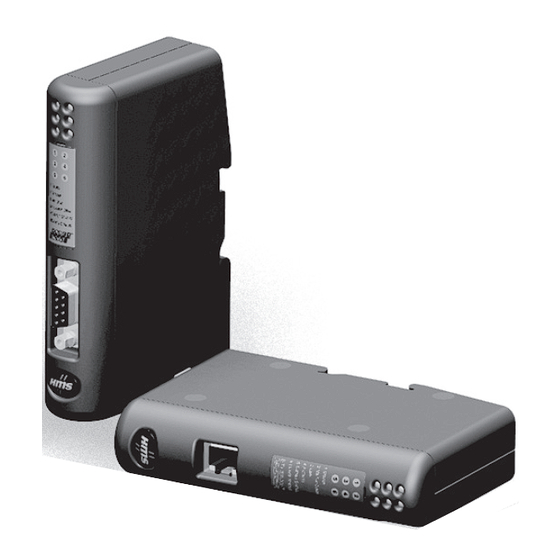
About the Anybus Communicator for PROFINET 11 1.2 External View For wiring and pin assignments, see “Connector Pin Assignments” on page 98. A: PROFINET Connector (Ethernet) This connector is used to connect the module to the net- work. See also... -
Page 12: Status Leds
About the Anybus Communicator for PROFINET 12 1.3 Status LEDs State Status 1 - Comm. Status Off line - No connection with IO Controller Green On line, Run - Connection with IO Controller established - IO Controller is in RUN state... -
Page 13: Hardware Installation
(The Anybus Configuration Manager software attempts to detect the serial port automatically. If not successful, select the correct port manually in the “Port”-menu) 7. Configure the Anybus Communicator using the Anybus Configuration Manager and download the configuration 8. Set up the PROFINET communication in accordance with the module configuration Anybus Communicator PROFINET User Manual Doc: HMSI-27-309, Rev. -
Page 14: Software Installation
About the Anybus Communicator for PROFINET 14 1.5 Software Installation 1.5.1 Anybus Configuration Manager System requirements • Pentium 133 MHz or higher • 650 MB of free space on the hard drive • 32 MB RAM • Screen resolution 800 x 600 (16 bit color) or higher •... -
Page 15: Basic Operation
2. Basic Operation 2.1 General The Anybus Communicator gateway is designed to exchange data between a serial sub-network and a higher level network. Unlike most other gateway devices of similar kind, it does not have a fixed protocol for the sub-network, and can be configured to handle almost any form of serial communication. -
Page 16: Data Exchange Model
Read/Write Subnetwork: Read Only Subnetwork: Read/Write Fieldbus: Read Only Fieldbus: Read/Write Fieldbus: E-mail Client: Read Only E-mail Client: Read Only E-mail Client: SSI: Read Only SSI: Read/Write SSI: 0x??? 0x1FF 0x3FF Anybus Communicator PROFINET User Manual Doc: HMSI-27-309, Rev. 3.11... -
Page 17: Data Exchange Example
Input Register in the Temperature- Serial Device - Temperature Regulator Regulator. Output Register Input Register The Temperature Regulator has two registers, holding the Setpoint Temperature Actual Temperature Temperature Setpoint and the Actual Temperature respectively. Anybus Communicator PROFINET User Manual Doc: HMSI-27-309, Rev. 3.11... -
Page 18: Subnetwork Protocol
2.3 Subnetwork Protocol 2.3.1 Protocol Modes The Anybus Communicator features three distinct modes of operation regarding the subnetwork com- munication, called “Master Mode”, “Generic Data Mode” and “DF1 Master Mode”. Note that the pro- tocol mode only specifies the basic communication model, not the actual subnetwork protocol. -
Page 19: Master Mode
There is one exception to this rule; the broadcaster. Most protocols offer some way of broadcasting mes- sages to all nodes on the network, without expecting them to respond to the broadcasted message. This is also reflected in the Anybus Communicator, which features a dedicated broadcaster node. Gateway... -
Page 20: Generic Data Mode
Gateway Subnetwork Devices In the figure above, the Anybus Communicator “consumes” data that is “produced” by a node on the subnetwork. This “consumed” data can then be accessed from the higher level network. This also works the other way around; the data received from the higher level network is used to “produce” a message on the subnetwork to be “consumed”... -
Page 21: Profinet Io
PROFIBUS GSD file, and is based on the EXtensible Markup Language (XML). This file holds information about the device (in this case the Anybus Communicator), its features, and possible I/O configurations. The latest version of the GSDML file for the Anybus Communicator can be downloaded from the HMS website, “www.anybus.com”. -
Page 22: Data Representation (Io Data & Record Data)
Note the “unused” part of the output data area.The reason for this is that only 272 bytes (128+64+64+16) are actually used in the I/O module configuration, although IO Size Out is set to 400 bytes. Anybus Communicator PROFINET User Manual Doc: HMSI-27-309, Rev. 3.11... -
Page 23: Modbus-Tcp (Read-Only)
The function code in the query is not supported 0x02 Illegal data address The data address received in the query is outside the initialized memory area 0x03 Illegal data value The data in the request is illegal Anybus Communicator PROFINET User Manual Doc: HMSI-27-309, Rev. 3.11... -
Page 24: File System
3. File System 3.1 General General The Anybus Communicator features a built-in file system, which is used to store information such as web files, network communication settings, e-mail messages etc. Storage Areas The file system consists of the different storage areas: •... -
Page 25: File System Overview
ASCII files which can be altered using a standard text editor. Note that some of these files may also be altered by the Anybus Communicator itself, e.g. when using SSI (see “Server Side Include (SSI)” on page 35). -
Page 26: Basic Network Configuration
TCP/ IP settings during runtime. DHCP/BootP The Anybus Communicator can retrieve the TCP/IP settings from a DHCP or BootP server. If no DHCP server is found, the module will fall back on its current settings (i.e. the settings currently stored in “\ethcfg.cfg”). -
Page 27: Ethernet Configuration File ("Ethcfg.cfg")
Basic Network Configuration 27 4.2 Ethernet Configuration File (“ethcfg.cfg”) 4.2.1 General To be able to participate on the network, the Anybus Communicator needs a valid TCP/IP configura- tion. These settings are stored in the system file “\ethcfg.cfg”. File Format: [IP address] xxx.xxx.xxx.xxx... -
Page 28: Profinet Settings
The file “\pnio.cfg” holds various PROFINET-related settings. The file is read once during startup, i.e. the Anybus Communicator must be restarted in order for any changes to have effect (unless its contents has been changed by an IO Controller/Supervisor via the DCP protocol. In such case, the settings will have effect immediately). -
Page 29: Anybus Ipconfig (Hicp)
The Anybus Communicator supports the HICP protocol used by the Anybus IPconfig utility from HMS, which can be downloaded free of charge from the HMS website. This utility may be used to con- figure the network settings of any Anybus product connected to the network. Note that if successful, this will replace the settings currently stored in the configuration file (“ethcfg.cfg”). -
Page 30: Ftp Server
Username1:Password1 Username2:Password2 Username3:Password3 Note: If no valid user accounts have been defined, the Anybus Communicator will grant admin-level access to all users. In such case, the FTP accepts any username/password combination, and the root directory will be “\”. Anybus Communicator PROFINET User Manual... -
Page 31: Ftp Connection Example (Windows Explorer)
1. Open the Windows Explorer by right-clicking on the “Start” button and selecting “Explore”. 2. In the address field, type ftp://<user>:<password>@<address> - Substitute <address> with the IP address of the Anybus Communicator - Substitute <user> with the username - Substitute <password> with the password 3. -
Page 32: General
Files located in a directory which contains a file named “web_accs.cfg” Default Web Pages The Anybus Communicator contains a set of virtual files which can be used when building a web page for configuration of network parameters. These virtual files can be overwritten (not erased) by placing files with the same name in the root of disc 0. -
Page 33: Authorization
Please enter the password. Note that when using this feature, make sure to put the user/password files in a directory that is pro- tected from web access, see “Protected Files” on page 32. Anybus Communicator PROFINET User Manual Doc: HMSI-27-309, Rev. 3.11... -
Page 34: Content Types
SSI. This is done in the system file “\http.cfg”. File Format: [FileTypes] FileType1:ContentType1 FileType2:ContentType2 FileTypeN:ContentTypeN [SSIFileTypes] FileType1 FileType2 FileTypeN Note: Up to 50 content types and 50 SSI file types may be specified in this file. Anybus Communicator PROFINET User Manual Doc: HMSI-27-309, Rev. 3.11... -
Page 35: Server Side Include (Ssi)
Server Side Include (from now on referred to as SSI) functionality enables dynamic content to be used on web pages and in e-mail messages. SSI are special commands embedded in the source document. When the Anybus Communicator en- counters such a command, it will execute it, and replace it with the result (when applicable). -
Page 36: Functions
This function returns the currently used IP address. Syntax: <?--#exec cmd_argument="DisplayIP"--> DisplaySubnet This function returns the currently used Subnet mask. Syntax: <?--#exec cmd_argument="DisplaySubnet"--> DisplayGateway This function returns the currently used Gateway address. Syntax: <?--#exec cmd_argument="DisplayGateway"--> Anybus Communicator PROFINET User Manual Doc: HMSI-27-309, Rev. 3.11... - Page 37 This function returns “Arg1” if DHCP is supported, and “Arg2” if it is not. Syntax: <?--#exec cmd_argument="DisplayDhcpSupport( ’Arg1’, ’Arg2’ )"--> DisplayEmailServer This function returns the currently used SMTP server address. Syntax: <?--#exec cmd_argument="DisplayEmailServer"--> Anybus Communicator PROFINET User Manual Doc: HMSI-27-309, Rev. 3.11...
- Page 38 This function returns the PROFINET Station Type. Syntax: <?--#exec cmd_argument="DisplayStationType"--> DisplayVendorID This function returns the PROFINET Vendor ID. Syntax: <?--#exec cmd_argument="DisplayVendorId"--> DisplayDeviceID This function returns the PROFINET DeviceID. Syntax: <?--#exec cmd_argument="DisplayDeviceId"--> Anybus Communicator PROFINET User Manual Doc: HMSI-27-309, Rev. 3.11...
- Page 39 - Specifies the destination offset from the beginning of the Output Data area. - Specifies maximum number of characters to read (Optional) Default output: Success - Write succeeded Failure - Write failed Anybus Communicator PROFINET User Manual Doc: HMSI-27-309, Rev. 3.11...
- Page 40 %e or %E is used if the exponent is less than -4 or greater than or equal to the precision; oth- erwise %f is used. Trailing zeros and trailing decimal point are not printed. no argument is converted; print a % Anybus Communicator PROFINET User Manual Doc: HMSI-27-309, Rev. 3.11...
- Page 41 Read an unsigned byte-array from a CIP-object ray(class, inst, attr) CipReadUWordAr- Read an unsigned word-array from a CIP-object ray(class, inst, attr) CipReadULongAr- Read an unsigned longword-array from a CIP-object ray(class, inst, attr) Anybus Communicator PROFINET User Manual Doc: HMSI-27-309, Rev. 3.11...
- Page 42 Write a word value to a CIP-object CipWriteLong(class, inst, attr) Write a longword to a CIP-object CipWriteFloat(class, inst, attr) Write a floating point value to a CIP-object Default output: Write succeeded Write failed Anybus Communicator PROFINET User Manual Doc: HMSI-27-309, Rev. 3.11...
- Page 43 The [Append|Overwrite] parameter determines if the specified file shall be overwritten, or if the data in the file shall be appended. Syntax: <?--#exec cmd_argument="saveDataToFile( ’File name’, ’Object name’,[Ap- pend|Overwrite] )"--> Default output: Success - Form saved to file Failure - Failed to save form Anybus Communicator PROFINET User Manual Doc: HMSI-27-309, Rev. 3.11...
- Page 44 This function is used to set the EtherNet/IP Scanner to Run or Idle. A variable called “scanner_state” shall be sent to the page with the value “run” or “idle” (other values will be ignored). Syntax: <?--#exec cmd_argument="setScannerMode"--> Default output: Failure - Change scanner mode not possible Anybus Communicator PROFINET User Manual Doc: HMSI-27-309, Rev. 3.11...
-
Page 45: Changing Ssi Output
The contents of this file can be redirected by placing the line “[File path]” on the first row, and a file path on the second. Example: [File path] \user\ssi_strings.cfg In this example, the settings described above will be loaded from the file “user\ssi_strings.cfg”. 1. “%s” includes the filename in the string Anybus Communicator PROFINET User Manual Doc: HMSI-27-309, Rev. 3.11... -
Page 46: Temporary Ssi Output Change
<?--#exec cmd_argument="ssiOutput( ’Success string’, ’Failure string’"--> Example: This example shows how to change the output strings for a scanf SSI call. <?--#exec cmd_argument="ssiOutput ( ’Parameter1 updated’, ’Error’ )"--> <?--#exec cmd_argument="scanf( ’Parameter1’, ’%d’, OutWriteByte(0) )"--> Anybus Communicator PROFINET User Manual Doc: HMSI-27-309, Rev. 3.11... -
Page 47: E-Mail Client
• “Server Side Include (SSI)” on page 35 Server Settings The Anybus Communicator needs a valid SMTP server configuration in order to be able to send e-mail messages. These settings are stored in the system file “\ethcfg.cfg”. See also... •... -
Page 48: E-Mail Definitions
Headers Optional; may be used to provide additional headers. Message The actual message. Note: Hexadecimal values must be written with the prefix “0x” in order to be recognized by the module. Anybus Communicator PROFINET User Manual Doc: HMSI-27-309, Rev. 3.11... -
Page 49: Navigating Acm
Values can be specified in decimal form (e.g. “42”), or in hexadecimal format (e.g. “0x2A”). • D: Information Section This section holds information related to the currently se- lected parameter. Anybus Communicator PROFINET User Manual Doc: HMSI-27-309, Rev. 3.11... -
Page 50: Drop-Down Menus
Upload Password(6) (max. 6 characters) CAUTION: Always keep a copy of the password in a safe place. A lost password cannot be re- trieved! • Exit Close ACM. Anybus Communicator PROFINET User Manual Doc: HMSI-27-309, Rev. 3.11... - Page 51 The Wizard is displayed each time a new configuration is created. “New” menu is selected Select language Selects which language to use. The new setting will be active the next time the pro- gram is launched. Anybus Communicator PROFINET User Manual Doc: HMSI-27-309, Rev. 3.11...
- Page 52 Contents/Search For Help On... Opens a built-in browser window with a link to the Anybus support website. • About... Displays general information about the gateway and the current version of ACM. Anybus Communicator PROFINET User Manual Doc: HMSI-27-309, Rev. 3.11...
-
Page 53: Toolbar Icons
Clicking on this icon will launch the Node Monitor (see “Node Monitor” on page 54) Node Monitor • Add Transaction(s) These icons are used to add transactions to the currently selected node. Transactions Transaction Anybus Communicator PROFINET User Manual Doc: HMSI-27-309, Rev. 3.11... -
Page 54: Basic Settings
General During start-up the fieldbus interface of the Anybus Communicator is initialized to fit the configuration created in the Anybus Configuration Manager. Optionally, some initialization parameters can be set manually to provide better control over how the data shall be treated by the module. -
Page 55: Communicator Parameters
This mode is intended for “Query & Response”-based protocols, where a single Master exchanges data with a number of Slaves. This mode is intended for the DF1 protocol. The Anybus Communicator can only be con- figured as a Master with half-duplex communication. -
Page 56: Sub-Network Parameters
• Generic Data Mode The Message Delimiter specifies the time that separates two messages in steps of 10 µs. Anybus Communicator PROFINET User Manual Doc: HMSI-27-309, Rev. 3.11... -
Page 57: Chapter 11 Nodes
To gain access to the parameters described in this section, select a node in the Navigation Section. Parameter Description Slave Address The value entered here may be used to set the node address in certain commands. For more information, see “The Command Editor” on page 43. Anybus Communicator PROFINET User Manual Doc: HMSI-27-309, Rev. 3.11... -
Page 58: Chapter 12 Transactions
Please refer to “DF1 Protocol Mode” on page 46. Theoretically, the gateway supports up to 150 transactions. The actual number may however be less de- pending on the memory requirements of the defined transactions. Anybus Communicator PROFINET User Manual Doc: HMSI-27-309, Rev. 3.11... -
Page 59: Adding & Managing Transactions
To increase readability, each node can be given a unique name using this function a. Only available if more than one node exists b. Only available in Master Mode c. Only available in Generic Data Mode Anybus Communicator PROFINET User Manual Doc: HMSI-27-309, Rev. 3.11... -
Page 60: Transaction Parameters (Master Mode)
This parameter specifies the location of the trigger byte in internal memory (only rele- vant when “Update mode” is set to “Change of state on trigger”). Valid settings range from 0x200 to 0x3FF and 0x400 to 0xFFF Anybus Communicator PROFINET User Manual Doc: HMSI-27-309, Rev. 3.11... -
Page 61: Parameters (Response)
The location of the trigger byte is specified by the “Trigger byte address” parameter below. Trigger byte address This parameter specifies the location of the trigger byte in the internal memory buffer. Valid settings range from 0x000 to 0x1FF and 0x400 to 0xFFF Anybus Communicator PROFINET User Manual Doc: HMSI-27-309, Rev. 3.11... -
Page 62: Transaction Parameters (Generic Data Mode)
(relevant only when “Update mode” is set to “Cyclically”, “On data change” or “Change of state on trigger”). The entered value is multiplied by 10. An entered value of 5 will result in 50 ms. Anybus Communicator PROFINET User Manual Doc: HMSI-27-309, Rev. 3.11... -
Page 63: Consume Transactions
Valid settings range from 0x000 to 0x1FF and 0x400 to 0xFFF. Please note that the trigger byte address must be unique to each transaction. It can not be shared by two or more transactions. Anybus Communicator PROFINET User Manual Doc: HMSI-27-309, Rev. 3.11... -
Page 64: Transaction Editor
This is followed by a two-byte checksum. The checksum calculation starts with the second byte in the transaction. The transaction ends with a byte constant, the ETX (0x03). Anybus Communicator PROFINET User Manual Doc: HMSI-27-309, Rev. 3.11... -
Page 65: Frame Objects
Parameter Section. It is also possible to edit the frame objects in a trans- action in a more visual manner using the Transaction Editor, see “Transaction Editor” on page 34. Anybus Communicator PROFINET User Manual Doc: HMSI-27-309, Rev. 3.11... -
Page 66: Constant Objects (Byte, Word, Dword)
To set the value of the object, select it in the Navigation Section and enter the desired value in the Pa- rameter section. Parameter Description Value Constant value Anybus Communicator PROFINET User Manual Doc: HMSI-27-309, Rev. 3.11... -
Page 67: Limit Objects (Byte, Word, Dword)
Note: The value must be larger than the Minimum Value. Minimum Value This is the smallest allowed value for the range. Range:0x00 to 0xFEh(byte) 0x0000 to 0xFFFEh(word) 0x00000000 to 0xFFFFFFFEh(dword) Note: The value must be less than the Maximum Value. Anybus Communicator PROFINET User Manual Doc: HMSI-27-309, Rev. 3.11... -
Page 68: Data Object
The specified data block is forwarded from the sub-network to the higher level network. The End- or Length-character will be generated by the gateway automatically (if applicable). The End- or Length-character itself may either be forwarded to the higher level network or dis- carded. Anybus Communicator PROFINET User Manual Doc: HMSI-27-309, Rev. 3.11... - Page 69 Only relevant for Consume/Response transactions b. Only used if “Object Delimiter” is set to “End Character” or “End Character Visible” Anybus Communicator PROFINET User Manual Doc: HMSI-27-309, Rev. 3.11...
-
Page 70: Checksum Object
The checksum is transmitted in binary format. • ASCII All characters in the checksum are converted to ASCII values. a. In Generic Data Mode the Start character (if used) will not be included in the checksum calculation. Anybus Communicator PROFINET User Manual Doc: HMSI-27-309, Rev. 3.11... -
Page 71: Chapter 14 Commands
Just like other transactions, the frame objects of added command may be edited in the Navigation/Parameter Section or using the Transaction Editor. Note however that certain frame objects may be locked for editing. Anybus Communicator PROFINET User Manual Doc: HMSI-27-309, Rev. 3.11... -
Page 72: Drop-Down Menu
Delete the currently selected command from the list. Note that some commands are fixed and cannot be deleted. 8.2.2 Toolbar Icons The toolbar features icons for the Add, Edit and Delete Command functions. Add Command Edit Command Delete Command Anybus Communicator PROFINET User Manual Doc: HMSI-27-309, Rev. 3.11... -
Page 73: The Command Editor
Allow Broadcasting Specifies if it is allowed to broadcast the command (only relevant in Master Mode) Produce The command is producing data (Generic Data Mode only) Consume The command is consuming data (Generic Data Mode only) Anybus Communicator PROFINET User Manual Doc: HMSI-27-309, Rev. 3.11... -
Page 74: Drop-Down Menu
Settings associated with the object can be edited by the user. [SlaveAddress] Value will be retrieved from the “SlaveAddress”-parameter (see “Node Parameters” on page 27). (other settings) Other settings are no longer supported. Anybus Communicator PROFINET User Manual Doc: HMSI-27-309, Rev. 3.11... -
Page 75: Example: Specifying A Modbus-Rtu Command In Master Mode
Name the new command by entering its name in the “Command Name” field, and enter a suitable func- tion code in the “Command ID”-field. If the command is allowed to be broadcasted, check the “Allow Broadcasting” checkbox. Anybus Communicator PROFINET User Manual Doc: HMSI-27-309, Rev. 3.11... -
Page 76: Df1 Protocol Mode
Chapter 9 9. DF1 Protocol Mode This mode makes the Anybus Communicator act as a DF1 protocol master on the sub-network. 9.1 General In DF1 master mode, communication is based on “services”. A “service” represents a set of commands and operations on the sub-network, that is predefined in the Anybus Communicator. Each service is associated with a set of parameters controlling how and when to use it on the sub-network. -
Page 77: Communicator Parameters
Value Description This mode is intended for the DF1 protocol. The Anybus Communicator can only be con- figured as a Master with half-duplex communication. Note: This is the only mode available if you intend to configure an ABC module for DF1. -
Page 78: Sub-Network Parameters
The default value is given as 100 in the parameter window. Each change of 10 ms either increases or decreases this value by 1, i.e. 99 represents a poll time of 990 ms and 101 represents a poll time of 1010 ms. Anybus Communicator PROFINET User Manual Doc: HMSI-27-309, Rev. 3.11... -
Page 79: Node Parameters
A total of 50 services are allowed. The Anybus Communicator supports a selection of DF1 commands. When the gateway is going to ex- ecute a service, it automatically chooses the appropriate DF1 command(s) that are used to perform the service on the selected DF1 node type. -
Page 80: Available Services
Response Trigger byte The memory location of the trigger byte this service uses for updates on trigger 0x05FF address byte changes Valid settings range from 0x200 to 0x3FF and 0x400 to 0xFFF Anybus Communicator PROFINET User Manual Doc: HMSI-27-309, Rev. 3.11... -
Page 81: Integrity Check
The number of bytes, read from the DF1 network, to write to the area determined by the Offset parameter Offset The offset in the internal memory buffer in the module, where the data shall be read. Anybus Communicator PROFINET User Manual Doc: HMSI-27-309, Rev. 3.11... -
Page 82: Read Data
Read Data. The only difference is that data is read from the internal memory buffer in the Anybus Communicator and written to the sub-network bus, instead of being written to the internal memory buffer. -
Page 83: Sub-Network Monitor
Data allocated by a Query or Produce transaction Collision; area has been allocated more than once Grey Reserved (illustrates memory consumption, area can be allocated if necessary) Green Data allocated by Trigger byte, Transmit/Receive Counter, or Control/Status Registers Anybus Communicator PROFINET User Manual Doc: HMSI-27-309, Rev. 3.11... -
Page 84: Node Monitor
Generic Data Mode The selected command (Transaction Produce) is sent to the sub-network. It is not possible to monitor any responses etc. generated by other nodes. Command Section (Produce) Subnetwork (Not used) Anybus Communicator PROFINET User Manual Doc: HMSI-27-309, Rev. 3.11... -
Page 85: Navigating The Node Monitor
Status & Control Registers, and areas displayed in light grey represent the data that is used by the node. The data displayed in this section will be refreshed based on the refresh-icons in the toolbar. For more information, see “Toolbar Icons” on page 57. Anybus Communicator PROFINET User Manual Doc: HMSI-27-309, Rev. 3.11... -
Page 86: Drop-Down Menu
The number of columns will be fixed to 8. View This menu specifies the data representation in the Monitor Section. • Display the data in hexadecimal format. • Decimal Display the data in decimal format. Anybus Communicator PROFINET User Manual Doc: HMSI-27-309, Rev. 3.11... -
Page 87: Toolbar Icons
Click on “Stop” to stop automatic data refresh. Data will now only be Stop Resume refreshed if you click “Refresh” (see below). Press “Resume” to resume automatic refreshing of data. • Refresh Refreshes the data displayed in the Monitor Section. Refresh Anybus Communicator PROFINET User Manual Doc: HMSI-27-309, Rev. 3.11... -
Page 88: Data Logger
CII format for both directions. The time between the log-en- tries is displayed in a separate column. The data may optionally be saved in ASCII text format by clicking “Create Text file”. Click “Close” to exit. Anybus Communicator PROFINET User Manual Doc: HMSI-27-309, Rev. 3.11... -
Page 89: Configuration
“Size of logbuffer” (valid settings range from 1–512). Click “Apply” to validate the new settings. Click “OK” to exit. Anybus Communicator PROFINET User Manual Doc: HMSI-27-309, Rev. 3.11... -
Page 90: Configuration Wizards
This option is suitable for Modbus RTU-based net- works. See also “Wizard - Modbus RTU Master” on page 91. • Blank Configuration This option creates an empty configuration. Highlight the desired wizard and click “OK” to continue. Anybus Communicator PROFINET User Manual Doc: HMSI-27-309, Rev. 3.11... -
Page 91: Wizard - Modbus Rtu Master
Click “Next” to continue. Step 2: Physical Settings Select the physical properties of the sub- network. Click “Next” to continue. Steps 3 - 6 Consult the online help system for fur- ther information. Anybus Communicator PROFINET User Manual Doc: HMSI-27-309, Rev. 3.11... -
Page 92: Control And Status Registers
Read Status Register Write to Control Register Start Start CR_HS_CONFIRM= SR_HS_CONFIRM= SR_HS_SEND? CR_HS_SEND? Read Status Register Write to Control Register Set CR_HS_CONFIRM Toggle CR_HS_SEND to SR_HS_SEND Done Done Anybus Communicator PROFINET User Manual Doc: HMSI-27-309, Rev. 3.11... -
Page 93: Data Consistency
Therefore, the fieldbus control system should not wait for this bit to be set before communicating with the sub-network devices; it should be considered as an aid for the fieldbus control system to know when all data has been updated. Anybus Communicator PROFINET User Manual Doc: HMSI-27-309, Rev. 3.11... -
Page 94: Status Register Contents (Gateway To Control System)
Note: Conditions of type “Error” will eventually be followed by a “No Error” condition when the cause has been resolved. Conditions of type “Warning” are however considered informational and may not necessarily be followed by a “No Error” condition later on. Anybus Communicator PROFINET User Manual Doc: HMSI-27-309, Rev. 3.11... -
Page 95: Status Code In Generic Data Mode
Note: Conditions of type “Error” will eventually be followed by a “No Error” condition when the cause no longer is detected. Conditions of type “Warning” are however considered informational and may not necessarily be followed by a “No Error” condition later on. Anybus Communicator PROFINET User Manual Doc: HMSI-27-309, Rev. 3.11... -
Page 96: Control Register Contents (Control System To Gateway)
Enables the specified number of nodes, start- ing from the first node in the configuration. Remaining nodes will be disabled. 14.3.3 Control Codes in Generic Data Mode (No Control Codes are currently supported in this mode). Anybus Communicator PROFINET User Manual Doc: HMSI-27-309, Rev. 3.11... -
Page 97: Advanced Fieldbus Configuration
This is done in the Mailbox Editor, see below. (A mailbox message is a HMS specific command structure used for low-level communication with an Anybus-S interface. Consult the Anybus-S Parallel Design Guide and the fieldbus appendix for the de- sired fieldbus for further information.) -
Page 98: Connector Pin Assignments
Cable Shield Termination Termination Termination Termination A.2 Power Connector Description +24 VDC Notes: • Use 60/75 or 75 °C copper (Cu) wire only. • Minimum terminal tightening torque: 5–7 lb-in (0.5–0.8 Nm). Anybus Communicator PROFINET User Manual Doc: HMSI-27-309, Rev. 3.11... -
Page 99: Pc Connector
RS232 Tx (Output) DB9F : PC Description RS232 Rx (Input) 5 (female) RS232 Tx (Output) Signal Ground 6 - 9 1. The RJ11 (4P4C modular) is sometimes referred to as an RJ9. Anybus Communicator PROFINET User Manual Doc: HMSI-27-309, Rev. 3.11... -
Page 100: Subnetwork Interface
Connecting this signal directly to Protective Earth (PE) of other nodes may, in case of grounding loops etc., cause damage to the on-board serial transceivers. It is therefore generally recommended to connect it only to Signal Ground (if available) of other nodes. Anybus Communicator PROFINET User Manual Doc: HMSI-27-309, Rev. 3.11... -
Page 101: Typical Connection (Rs485)
Note: Bias resistors are normally not needed on RS422, but may be required when using 4-wire RS485. A.4.7 Typical Connection (RS232) RS232 Tx RS232 Rx RS232 Rx RS232 Tx Signal Signal Ground Ground Cable Shield Anybus Communicator Device Anybus Communicator PROFINET User Manual Doc: HMSI-27-309, Rev. 3.11... -
Page 102: Technical Specification
B.3 Environmental Characteristics Relative Humidity The product is designed for a relative humidity of 0 to 95 % non-condensing. Temperature Operating: 0 °C to +55 °C Non-operating: -25 °C to +85 °C Anybus Communicator PROFINET User Manual Doc: HMSI-27-309, Rev. 3.11... -
Page 103: Regulatory Compliance
COUPER L’ALIMENTATION ÉLECTRIQUE AVANT LE REMPLACEMENT OU LE RACCORDEMENT DES MODULES. ATTENTION – RISQUE D’EXPLOSION – NE PAS DÉCONNECTER L’ÉQUIPEMENT TANT QUE L’ALIMENTATION EST TOUJOURS PRÉSENTE OU QUE LE PRODUIT EST TOUJOURS EN ZONE EXPLOSIVE ACTIVE. Anybus Communicator PROFINET User Manual Doc: HMSI-27-309, Rev. 3.11... - Page 104 0.32 0.52 0.82 Galvanic isolation on sub-network interface • EN 60950-1 (2001) Pollution Degree 2 Material Group IIIb 250 V or 250 VDC working voltage 500 V secondary circuit transient rating Anybus Communicator PROFINET User Manual Doc: HMSI-27-309, Rev. 3.11...
-
Page 105: Appendix C Troubleshooting
• If no data is being transmitted, check the configuration in ACM. • If no data is received, check the sub-network cables. Also verify that the transmitted data is correct. Anybus Communicator PROFINET User Manual Doc: HMSI-27-309, Rev. 3.11... - Page 106 Appendix D D. ASCII Table (sp) " & < > Anybus Communicator PROFINET User Manual Doc: HMSI-27-309, Rev. 3.11...
- Page 107 It is provided "as is" without express or implied warranty of any kind. These notices must be retained in any copies of any part of this documentation and/or software. Anybus Communicator PROFINET User Manual Doc: HMSI-27-309, Rev. 3.11...
Need help?
Do you have a question about the Anybus Communicator and is the answer not in the manual?
Questions and answers