Sign In
Upload
Manuals
Brands
HMS Manuals
Control Unit
Anybus Communicator
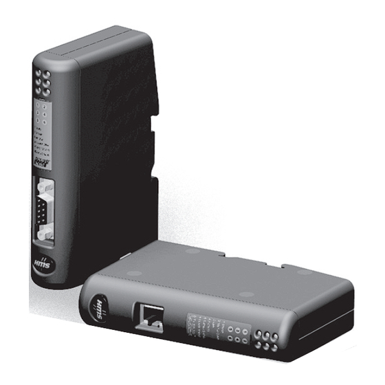
HMS Anybus Communicator Manuals
Manuals and User Guides for HMS Anybus Communicator. We have
2
HMS Anybus Communicator manuals available for free PDF download: User Manual
HMS Anybus Communicator User Manual (108 pages)
for PROFINET
Brand:
HMS
| Category:
Control Unit
| Size: 4 MB
Table of Contents
Table of Contents
3
Preface
8
About this Document
8
Related Documents
8
Document History
8
Conventions & Terminology
9
Glossary
9
Support
9
Chapter 1 About the Anybus Communicator for PROFINET
10
General
10
External View
11
Status Leds
12
Hardware Installation
13
Software Installation
14
Anybus Configuration Manager
14
Chapter 2 Basic Operation
15
General
15
Data Exchange Model
16
Memory Map
16
Data Exchange Example
17
Subnetwork Protocol
18
Protocol Modes
18
Protocol Building Blocks
18
Master Mode
19
Generic Data Mode
20
DF1 Master Mode
20
Profinet Io
21
General
21
I/O Configuration
21
GSDML File
21
Data Representation (IO Data & Record Data)
22
Modbus-TCP (Read-Only)
23
General
23
Data Representation (Modbus-TCP Register Map)
23
Supported Exception Codes
23
Chapter 3 File System
24
General
24
File System Overview
25
System Files
25
Chapter 4 Basic Network Configuration
26
General Information
26
Ethernet Configuration File ("Ethcfg.cfg")
27
General
27
IP Access Control
28
PROFINET Settings
28
Anybus Ipconfig (HICP)
29
Chapter 5 FTP Server
30
General
30
FTP Connection Example (Windows Explorer)
31
Chapter 6 Web Server
32
General
32
Authorization
33
Content Types
34
Chapter 7 Server Side Include (SSI)
35
General
35
Functions
36
Changing SSI Output
45
SSI Output String File
45
Temporary SSI Output Change
46
Chapter 8 E-Mail Client
47
General
47
E-Mail Definitions
48
Chapter 9 Navigating ACM
49
Main Window
49
Drop-Down Menus
50
Toolbar Icons
53
Chapter 10 Basic Settings
54
Fieldbus Settings
54
Communicator Parameters
55
Sub-Network Parameters
56
Chapter 11 Nodes
57
General
57
Adding & Managing Nodes
57
Node Parameters
57
Master Mode and Generic Data Mode
57
Chapter 12 Transactions
58
General
58
Adding & Managing Transactions
59
Transaction Parameters (Master Mode)
60
Parameters (Query & Broadcast)
60
Parameters (Response)
61
Transaction Parameters (Generic Data Mode)
62
Produce Transactions
62
Consume Transactions
63
Transaction Editor
64
Chapter 13 Frame Objects
65
General
65
Adding and Editing Frame Objects
65
Constant Objects (Byte, Word, Dword)
66
Limit Objects (Byte, Word, Dword)
67
Data Object
68
Variable Data Object
68
Checksum Object
70
Chapter 14 Commands
71
General
71
Adding & Managing Commands
71
Drop-Down Menu
72
Toolbar Icons
72
The Command Editor
73
General
73
Basic Navigation
73
Drop-Down Menu
74
Editing a Command
74
Example: Specifying a Modbus-RTU Command in Master Mode
75
Chapter 15 DF1 Protocol Mode
76
General
76
Communicator Parameters
77
Sub-Network Parameters
78
Node Parameters
79
Services
79
Available Services
80
Integrity Check
81
Read Diagnostics
81
Read Data
82
Write Data
82
Chapter 16 Sub-Network Monitor
83
General
83
Operation
83
Chapter 17 Node Monitor
84
General
84
Navigating the Node Monitor
85
Drop-Down Menu
86
Toolbar Icons
87
Chapter 18 Data Logger
88
General
88
Operation
88
Configuration
89
Chapter 19 Configuration Wizards
90
General
90
Selecting a Wizard Profile
90
Wizard - Modbus RTU Master
91
Chapter 20 Control and Status Registers
92
General
92
Handshaking Procedure
92
Data Consistency
93
Status Register Contents (Gateway to Control System)
94
General Information
94
Status Codes in Master Mode and DF1 Master Mode
94
Status Code in Generic Data Mode
95
Control Register Contents (Control System to Gateway)
96
General Information
96
Control Codes in Master Mode and DF1 Master Mode
96
Control Codes in Generic Data Mode
96
Chapter 21 Advanced Fieldbus Configuration
97
General
97
Mailbox Editor
97
Appendix A Connector Pin Assignments
98
PROFINET Connector (Ethernet)
98
Power Connector
98
PC Connector
99
Subnetwork Interface
100
General Information
100
Bias Resistors (RS485 Only)
100
Termination (RS485 & RS422 Only)
100
Connector Pinout (DB9F)
100
Typical Connection (RS485)
101
Typical Connection (RS422 & 4-Wire RS485)
101
Typical Connection (RS232)
101
Connector Pin Assignments
98
Technical Specification
102
Mechanical Properties
102
Electrical Characteristics
102
Environmental Characteristics
102
Regulatory Compliance
103
Appendix B Technical Specification
105
Appendix C Troubleshooting
105
Advertisement
HMS Anybus Communicator User Manual (90 pages)
EtherCAT to EtherNet/IP
Brand:
HMS
| Category:
Network Hardware
| Size: 6 MB
Table of Contents
Table of Contents
3
Preface
7
About this Document
7
Document Conventions
7
Information Symbols
8
Trademarks
8
About the Ethercat Terminology
8
Safety
9
Intended Use
9
General Safety
9
Cybersecurity
10
General Cybersecurity
10
Security Advisories
10
How to Report a Vulnerability
10
Product Cybersecurity Context
11
Security Defense in Depth Strategy
11
Purdue Model
12
Preparation
13
Cabling
13
Mechanical Tools and Equipment
13
System Requirements
13
Supported Operating Systems
13
Supported Web Browsers
13
HMS Software Applications
13
Third-Party Software Applications
14
Microsoft Excel
14
Software License Information
14
Support and Resources
14
About Anybus Communicator
15
Ethernet/Ip Scanner Communication
15
Ethernet/Ip Scanner Building Blocks
15
How the Communication Works
17
How the Data Exchange Works
19
Input Data
19
Output Data
19
Data Integrity
19
Installation
20
External Parts
20
Connector Port Guide
21
DIN Rail Mounting
22
Connect to Ethercat Network
23
Connect to Ethernet/Ip Network
24
Connect to Power
25
Power Connector Pinout
25
Security Switch
26
Lock the Cables
28
DIN Rail Demount
29
Before You Begin
29
Configuration Quick Guide
31
Prepare Configuration
31
Setup New Configuration
34
PLC Configuration
36
Verify Operation
37
Communicator Configuration
39
Connect the Communicator
39
Access the Built-In Web Interface from HMS Ipconfig
40
Access the Built-In Web Interface from a Web Browser
42
Communicator Built-In Web Interface Overview
43
Ethernet/Ip™ Scanner Communication Settings
44
To Use DHCP Server
44
To Configure IP Settings Manually
45
Naming the Host
46
Adapters
46
About Originator and Target
46
About Output and Input Data
46
Add Generic Adapter
47
Add Adapter from EDS File
48
Adapter Connection Settings
51
Ethercat Settings
53
Export Product ESI File
53
I/O Configuration
54
Map Area Object Order
55
Endian Swap
55
Convert between Big-Endian and Little-Endian
56
Live List
57
Data Exchange Control
58
Configuration Notes
59
Add Configuration Note
59
View and Edit Configuration Notes
61
Apply Configuration
62
To Use an Existing Configuration
63
PLC Configuration
64
PLC Device Security
64
Export Product ESI File
64
Canopen over Ethercat (Coe) Objects
65
Verify Operation
68
Communicator Status Monitor
68
Status Symbols
69
Communicator LED Indicators
70
Ethernet LED Indicators
72
Maintenance
73
Action on Fatal Error
73
Configuration Port IP Settings
74
Configuration File Handling
75
Export Configuration
75
Import Configuration
76
Clear and Revert Configuration
77
Firmware Management
78
View the Firmware Version
78
Firmware and Configuration Compatibility
78
Firmware File Validation
78
Update Firmware
79
Change Language
80
Troubleshooting
81
Diagnostics
81
I/O Data
81
Event Log
82
LED Status
83
Reset to Factory Settings
84
Before You Begin
84
Firmware Upgrade Error Management
86
Support
88
Support Package
88
End Product Life Cycle
89
Secure Data Disposal
89
Technical Data
90
Technical Specifications
90
Advertisement
Related Products
HMS Anybus AS-Interface Master
HMS Anybus CANopen Slave
HMS Anybus CC-Link Slave
HMS Anybus EtherNet/IP
HMS Anybus Communicator PROFINET-USS
HMS Anybus Communicator IIoT
HMS Anybus Communicator for Modbus RTU
HMS Anybus
HMS Anybus X-gateway Modbus-TCP
HMS Anybus X-gateway CANopen
HMS Categories
Fitness Equipment
Gateway
Exercise Bike
Treadmill
Elliptical Trainer
More HMS Manuals
Login
Sign In
OR
Sign in with Facebook
Sign in with Google
Upload manual
Upload from disk
Upload from URL