Table of Contents
Advertisement
Manual
Model 1222
Electric Steering Controller
» Software Version OS 15.0 «
Read Instructions Carefully!
Specifications are subject to change without notice.
© 2013 Curtis Instruments, Inc. ® Curtis is a registered trademark of Curtis Instruments, Inc.
© The design and appearance of the products depicted herein are the copyright of Curtis Instruments, Inc.
Curtis Instruments, Inc.
200 Kisco Avenue
Mt. Kisco, NY 10549
www.curtisinstruments.com
53122, OS15 1/29/13
Advertisement
Table of Contents
Troubleshooting

Related Manuals for Curtis 1222


Summary of Contents for Curtis 1222
- Page 1 Specifications are subject to change without notice. © 2013 Curtis Instruments, Inc. ® Curtis is a registered trademark of Curtis Instruments, Inc. © The design and appearance of the products depicted herein are the copyright of Curtis Instruments, Inc. 53122, OS15 1/29/13...
-
Page 3: Table Of Contents
4c. CONTROLLER FUNCTIONS MENU.........71 5. COMMISSIONING ...............72 6. INTERFACE WITH MASTER CONTROLLER....93 7. DIAGNOSTICS AND TROUBLESHOOTING....99 8. MAINTENANCE ..............110 Vehicle Design Considerations APPENDIX A EN14839 Compliance APPENDIX B Programming Devices APPENDIX C Specifications, 1222 Controller APPENDIX D Curtis 1222 Manual, os 15... -
Page 4: Table Of Contents
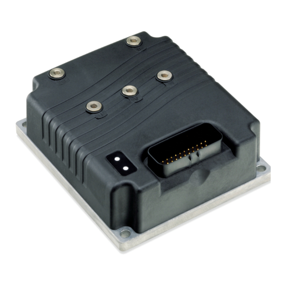
2 9 J A N U A R Y 2 0 1 3 D R A F T FIGURES / TABLES FIGURES fig. 1: Curtis 1222 controller.............. 1 fig. 2: Mounting dimensions, Curtis 1222 controller ......4 fig. 3a: Wiring diagram..............11 fig. 3b: Software control diagram ............12 fig. 4: Command Input Device “0”... -
Page 5: Overview
(EPS) systems. In these “steer by wire” systems, the AC steering gearmotor functions as an actuator to change the angle of the vehicle’s steered wheel(s) and thus change the direction of travel. The 1222 performs as the steering system controller, interpreting the steering command input and wheel position feedback, then driving the steering motor to move the steered wheel(s) to the desired position. - Page 6 ✓ 35-pin AMPSEAL logic connector. ✓ Software includes a library of pre-defined AC steering motor types from various manufacturers. ✓ Programmable motor temperature input prevents thermal damage to motor and supports all commonly used thermistors. Curtis 1222 Manual, os 15...
- Page 7 ✓ Reverse polarity protection on battery connections and short circuit protection on all output drivers. Familiarity with your Curtis controller will help you install and operate it prop- erly. We encourage you to read this manual carefully. If you have questions, please contact your local Curtis representative.
-
Page 8: Installation And Wiring
INSTALLATION AND WIRING MOUNTING THE CONTROLLER The outline and mounting hole dimensions for the 1222 controller are shown in Figure 2. The controller meets the IP65 requirements for environmental protection against dust and water. Nevertheless, in order to prevent external corrosion and leakage paths from developing, the mounting location should be carefully chosen to keep the controller as clean and dry as possible. - Page 9 EMC performance complies with applicable regulations; suggestions are presented in Appendix A. The 1222 controller contains ESD-sensitive components. Use appro- priate precautions in connecting, disconnecting, and handling the controller. See installation suggestions in Appendix A for protecting the controller from ESD damage.
- Page 10 Use high quality copper lugs and observe the recommended torque ratings. For best noise immunity the cables should not run across the center section of the controller. With multiple high current controllers, use a star ground from the battery terminal. Curtis 1222 Manual, os 15...
- Page 11 Low current signal wires should not be run next to the motor cables. When necessary they should cross the motor cables at a right angle to minimize noise coupling. Curtis 1222 Manual, os 15...
- Page 12 120Ω CAN terminating resistors at each end. If the vehicle wiring is done such that the 1222 is the last node in the chain, an external 120Ω terminating resistor should be provided by the OEM in the wiring harness.
- Page 13 Regulated low power +5V output. 22 Motor Temperature Sensor Motor temperature sensor. 23 CAN High CAN bus high. 24 Fault Output Steer fault output. 25 Command Encoder 1B Steer Command Encoder 1 input phase B. Curtis 1222 Manual, os 15...
-
Page 14: Table 2: Low Current Connections
32 Steer Motor Encoder 3B Steer Motor Encoder 3 input phase B. 33 Command Encoder 2A Steer Command Encoder 2 input phase A. 34 +5V Regulated low power +5V output. 35 CAN Low CAN bus low. Curtis 1222 Manual, os 15... -
Page 15: Controller Wiring: Safety Requirements
Controller Wiring CONTROLLER WIRING: Safety Requirements As shown in the wiring diagram (Figure 3a), the 1222’s keyswitch power must go through the traction controller so that when the keyswitch is turned off both controllers turn off. The fault output (Pin 24) should be able to shut down the traction system in the case of a serious fault;... -
Page 16: Fig. 3B: Software Control Diagram
Controller Wiring device input to its counterpart (steering to steering, feedback to feedback). If any of these input pairs do not match, the 1222 begins its fault sequence to bring the vehicle to a stop. As shown in the software control diagram (Figure 3b), the safety critical parts are included twice to provide redundancy: ·... - Page 17 1.5 V min Driver outputs The fault output shuts down the traction system if the 1222 has a fault. This output switches B+ to the high side of the traction main contactor and EM brake; without this signal, the system shuts down.
- Page 18 100 mA max 65 V ±8 kV (air +10V 10 V ±10% 100 mA max 65 V discharge) Ground 7, 18, 30 The total combined current from +5V and +10V outputs should not exceed 150 mA. Curtis 1222 Manual, os 15...
- Page 19 120Ω CAN terminating resistors at each end. If the vehicle wiring is done such that the 1222 is the last node in the chain, then an external 120Ω terminating resistor should be provided by the OEM in the wiring harness.
- Page 20 4 V max discharge) Falling edge= 1 V min Command Encoder 2A Command Encoder 2B Steer Motor Encoder 3A 31 10 kHz Steer Motor Encoder 3B 32 Steer Motor Encoder 4A 26 Steer Motor Encoder 4B 27 Curtis 1222 Manual, os 15...
-
Page 21: Programmable Parameters
3 — PROGRAMMABLE PARAMETERS PROGRAMMABLE PARAMETERS The 1222 controller has a number of parameters that can be programmed us- ing a Curtis 1313 handheld programmer or 1314 Programming Station. The programmable parameters allow the steering performance to be customized to fit the needs of specific applications. -
Page 22: Table 3: Programmable Parameter Menus
—Min Volts —Tolerance —Max Volts 3 – Sawtooth Sensor ....p. 42 —Swap Direction —Center Position (deg) —Absolute Mode —Min Volts —Fault Min —Max Volts —Fault Max —Swap Direction —Tolerance —Fault Min —Fault Max —Tolerance Curtis 1222 Manual, os 15... - Page 23 Even if you opt to leave most of the parameters at their default settings, it C A U T I O N is imperative that you perform the procedures outlined in Section 5, which set up the basic system characteristics for your application. Curtis 1222 Manual, os 15...
- Page 24 Supervisory analog input command It is best practice to wire the primary and supervisory input sig- nals in an “X” configuration (0–5V and 5V–0). However, the 1222 has independent maps and will support redundant signals that move in the same direction.
- Page 25 When this steering command is used, primary sawtooth and offset sawtooth channels are both required (and together serve as the primary and supervisory devices). NAME FUNCTION Analog 1 Primary sawtooth input (Command Analog 1) Analog 3 19 Offset sawtooth input (Command Analog 3) Curtis 1222 Manual, os 15...
- Page 26 Command Input Parameters INPUT DEVICE PARAMETER, cont’d 4 = CAN Sensor command, where the input to the 1222 comes via a CAN bus message (i.e., “steer-by-wire”). The CAN sensor may be set up as either an absolute or relative position device, using the Absolute Mode parameter (see page 30).
- Page 27 Sets the maximum threshold for the Analog 3 steer command pot input. 0x400C 0x00 0 – 1023 If the Analog 3 steer command pot voltage rises above this threshhold for 60 ms, a fault is issued. Curtis 1222 Manual, os 15...
-
Page 28: Fig. 4: Command Input Device "0" Signal Flow
2 9 J A N U A R Y 2 0 1 3 D R A F T 3 — PROGRAMMABLE PARAMETERS: Command Input Parameters Fig. 4 Command Input Device “0” signal flow (Analog 1 shown; Analog 3 is similar). Curtis 1222 Manual, os 15... -
Page 29: Fig. 5: Command Input Device "1" Signal Flow
On / Off Changes the direction (left or right) of the Encoder 2 steer command 0x4069 0x00 On / Off input. Fig. 5 Command Input Device “1” signal flow (Encoder 1 shown; Encoder 2 is similar). Curtis 1222 Manual, os 15... - Page 30 (Command Sin/Cos Sensor Angle 2) and the actual inputs (Command Sin/Cos Sensor Angle) is greater than the set Tolerance voltage for 60 ms, a fault is issued. This provides a second level of fault detection and triggers a separate SinCos Command fault. Curtis 1222 Manual, os 15...
-
Page 31: Fig. 6: Command Input Device "2" Signal Flow
2 9 J A N U A R Y 2 0 1 3 D R A F T 3 — PROGRAMMABLE PARAMETERS: Command Input Parameters Fig. 6 Command Input Device “2” signal flow. Curtis 1222 Manual, os 15... - Page 32 If the error is greater than the Tolerance voltage for 60 ms, a fault is issued. This provides a second level of fault detection and triggers a separate Sawtooth Command Sensor fault. Curtis 1222 Manual, os 15...
-
Page 33: Fig. 7: Command Input Device "3" Signal Flow
2 9 J A N U A R Y 2 0 1 3 D R A F T 3 — PROGRAMMABLE PARAMETERS: Command Input Parameters Fig. 7 Command Input Device “3” signal flow. Curtis 1222 Manual, os 15... -
Page 34: Fig. 8: Command Input Device "4" Signal Flow
PDO must be sent to the main processor and one to the supervisor. For additional security, it is recommended that the PDO sent to the supervisor be the opposite polarity and that Swap Direction be set for the supervisor only. Contact Curtis technical support for help with setting up PDOs. -
Page 35: Fig. 9: Steer Command Map
The map in this example is set up to provide a deadband in the center (points D and E) and less sensitivity at the ends (between A and B, and between G and H). Fig. 9 Steer Command Map. Curtis 1222 Manual, os 15... - Page 36 Steer Command of zero % equals a Steer Command (deg) of zero. This is necessary to ensure that the auto-center functions work correctly and will aid in system troubleshooting. Curtis 1222 Manual, os 15...
- Page 37 0x40BA 0x00 0 – 5000 force feedback coil. When setting this parameter it is useful to view the estimated steer motor torque (Monitor » Steer Motor » Motor Torque). Fig. 10 Force feedback signal flow. Curtis 1222 Manual, os 15...
- Page 38 Supervisory analog feedback It is best practice to wire the primary and supervisory input sig- nals in an “X” configuration (0–5V and 5V–0). However, the 1222 has independent maps and will support redundant signals that move in the same direction.
- Page 39 When this position feedback is used, primary sawtooth and offset sawtooth channels are both required (and together serve as the primary and supervisory feedback devices). NAME FUNCTION Analog 5 Primary Sawtooth input (Position Analog 5) Analog 6 Offset Sawtooth input (Position Analog 6) Curtis 1222 Manual, os 15...
- Page 40 This option is provided to allow systems not compliant with EN 13849 to be set up without having to supply connections to the supervisory inputs from the single primary feedback device. Curtis 1222 Manual, os 15...
-
Page 41: Fig. 10: Position Feedback Device "0" Signal Flow
If the Analog 6 steer position feedback pot voltage rises above this threshold for 60 ms, a fault is issued. Fig. 10 Position Feedback Device “0” signal flow (Analog 5 shown; Analog 6 is similar). Curtis 1222 Manual, os 15... -
Page 42: Fig. 11: Position Feedback Device "1" Signal Flow
Auto Center. If the home switch is at the same position as center, set Center Offset to zero. Fig. 11 Position Feedback Device “1” signal flow (Encoder 3 shown; Encoder 4 is similar). Curtis 1222 Manual, os 15... - Page 43 Home switch is On and to the left if it is Off. The home position is just to the right of the switch transition in method 2 and just to the left of the switch transition in method 3. Curtis 1222 Manual, os 15...
- Page 44 Defines the allowable time for homing to find home. A Home Position 0x40F4 0x00 1 – 50 Not Found fault is issued if the homing goes longer than the set Homing Timeout without finding home. Curtis 1222 Manual, os 15...
- Page 45 Tolerance voltage for 60 ms, a fault is issued. This provides a second level of fault detection and triggers a separate SinCos feedback fault. Fig. 12 Position Feedback Input Device “2” signal flow. Curtis 1222 Manual, os 15...
- Page 46 Tolerance voltage for 60 ms, a fault is issued. This provides a second level of fault detection and triggers a separate Sawtooth Command fault. Fig. 13 Position Feedback Input Device “3” signal flow. Curtis 1222 Manual, os 15...
- Page 47 Note: Setting this parameter to a value greater than zero requires the traction controller’s software (VCL and parameters) to permit interlock braking. Please review your traction software before setting this parameter to a non-zero value. Curtis 1222 Manual, os 15...
- Page 48 0 – 2 0 = No steer contactor (Contactor Driver = Off). This setting is used when the 1222 B+ stud is wired to a battery with no steer contactor. This setting is not recommended and may not meet the required vehicle safety standards.
- Page 49 RANGE DESCRIPTION Input Type 0 – 2 This parameter defines how the traction speed is determined by the 1222. 0x40B5 0x00 0 – 2 0 = Traction speed input disabled. 1 = Encoder1 input (not allowed if Command Input Device = 1) 2 = CAN bus PDO message from the traction controller.
- Page 50 Stall Timeout parameter. When this condition is detected, a fault is issued (code 36, Motor Stalled). A setting of Stall Speed = 0 turns off this fault check. Curtis 1222 Manual, os 15...
- Page 51 Accumulated will count down if either the Error Tolerance ≤ 5 the Wheel Speed (deg/s) ≥10. Error Time must be set long enough for the steered wheel to reverse direction and reach the minimum speed (Speed Tolerance (deg/s)) under the worst case conditions. Curtis 1222 Manual, os 15...
- Page 52 • Swap Encoder3 Direction On / Off Changes the steer motor encoder’s effective direction of rotation. The steer 0x4014 0x00 On / Off encoder provides data used to determine steer speed. Curtis 1222 Manual, os 15...
- Page 53 The motor temperature cutback feature will reduce traction speed between the Temperature Hot and Temperature Max setpoints, but it will not inhibit the 1222 steering. The motor temperature compensation feature will adapt the motor control algorithms to varying motor temperatures, for improved efficiency and more consistent performance.
- Page 54 Temp 1 = 0x4087 0x00 Temp 2 = 0x4089 0x00 Temp 3 = 0x408B 0x00 Temp 4 = 0x408D 0x00 Temp 5 = 0x408F 0x00 Temp 6 = 0x4091 0x00 Temp 7 = 0x4093 0x00 Curtis 1222 Manual, os 15...
- Page 55 Sets the supervisor Node ID of the CANopen Slave system. This is the 0x40B2 0x00 1 – 127 second of the two node IDs that need to be set up for the 1222 controller. The Node ID Supervisor should always be different from the Node ID. •...
- Page 56 If the gain is set too high, you may experience oscillations as the controller tries to control velocity. If it is set too low, the motor may take a long time to approach the exact commanded velocity. See Figure 15. Curtis 1222 Manual, os 15...
-
Page 57: Fig. 14: Position Control Signal Flow
3 — PROGRAMMABLE PARAMETERS: Motor Control Tuning Parameters “ ” is the percentage of determined Position Kp by the Steering Sensitivity Map; see Fig. 16. Fig. 14 Position Control signal flow. Fig. 15 Velocity Control signal flow. Curtis 1222 Manual, os 15... -
Page 58: Fig. 16: Steering Sensitivity Map
X axis. (RPM) LS Sensitivity Low Speed 100% Mid Speed 100% High Speed HS Sensitivity The map adjusts the proportional gain (Position Kp) as a function of traction speed. Fig. 16 Steering Sensitivity Map. Curtis 1222 Manual, os 15... - Page 59 field. This current will run in the steer motor whenever the bridge is enabled (Interlock = On). Pre-fluxing the steer motor improves steering response, but because it also reduces efficiency and causes controller and steer motor heating, this parameter is typically set to zero. Curtis 1222 Manual, os 15...
- Page 60 AC motors. The table also provides appropriate settings for the FW Base Speed parameter. If your motor is not included here, consult your local Curtis customer support engineer for information on how to set these three parameters based on your application and motor.
-
Page 61: A. Monitor Menu
—To Traction Controller ... p. 69 —Following Error (deg) —Enable Traction —Wheel Speed (deg/s) —Traction Cutback —Steer Command Error (deg) —Traction Fault Action —Wheel Position Error (deg) —Encoder Position Error (deg) —Home Reference Error (deg) Curtis 1222 Manual, os 15... - Page 62 -100.0 – 100.0 % The operator’s redundant Steer Command 0x446A 0x00 -32768 – 32767 (in percent) that is the input into the com- mand map. The output of the command map is the Steer Command 2 (in degrees). Curtis 1222 Manual, os 15...
- Page 63 Angle Raw 2 (deg) -2880.0 – 2880.0 This variable is used by both the Sin/Cos 0x44BF 0x00 -32768 – 32767 and Sawtooth sensor inputs. It is calculated from the sensor input voltages (pins 8 and 19). Curtis 1222 Manual, os 15...
- Page 64 Encoder 2B On / Off Command Encoder 2B switch input 0x447B 0x00 On / Off On or Off (pin 20). This can be used to verify that phase B of Command Encoder 2 is operating correctly. Curtis 1222 Manual, os 15...
- Page 65 Steer Counts = CAN 2 Steer Command minus the Center Offset parameter. In Relative Position mode, CAN 2 Steer Counts = CAN 2 Steer Command minus the relative center angle (which is recalculated each time the interlock is enabled). Curtis 1222 Manual, os 15...
- Page 66 Sawtooth sensors. Position 2 Raw (deg) -180.0° – 180.0° The angle calculated by the supervisory 0x44C1 0x00 -32768 – 32767 microprocessor from the input voltages (pins 16 and 17) for the Sin/Cos or Sawtooth sensors. Curtis 1222 Manual, os 15...
- Page 67 On / Off Steer Motor Encoder 4B switch input On or Off 0x447D 0x00 On / Off (pin 27). This can be used to verify that phase B of Steer Motor Encoder 4 is operating correctly. Curtis 1222 Manual, os 15...
- Page 68 Home Reference Error (deg) -180.0° – 180.0° Home Reference Error = Home Reference 0x44CC 0x00 -32768 – 32767 minus Home Reference 2. If the difference exceeds the programmed Home Reference Tolerance, a fault is issued (code 54: Home Reference Tolerance Fault). Curtis 1222 Manual, os 15...
- Page 69 0 – 100 % Steer contactor driver PWM output (pin 2). 0x44A4 0x00 0 – 32767 Force Feedback Driver PWM 0 – 100 % Force feedback driver PWM output (pin 5). 0x44A7 0x00 0 – 32767 Curtis 1222 Manual, os 15...
- Page 70 Steer motor temperature as measured by 0x441B 0x00 -32768 – 32767 the motor temperature sensor input (pin 22). Temperature Sensor Voltage 0.00 – 10.00 V Voltage measured at the motor 0x4410 0x00 0 – 1023 temperature sensor input (pin 22). Curtis 1222 Manual, os 15...
- Page 71 Interlock = On command 5= “Operation Enabled”: controller enabled, motor bridge enabled, Interlock = On 13= “Fault Reaction State”: controller processing a shutdown fault action 14= “Fault”: controller shut down by shutdown fault action, Fault Output = Off. Curtis 1222 Manual, os 15...
- Page 72 On. Monitor Menu: CAN STATUS DISPLAY VARIABLE RANGE DESCRIPTION CAN NMT State 0 – 255 Controller CAN NMT state: 0x1C00 0x00 0 – 255 0= initialization 4= stopped 5= operational 127= pre-operational. Curtis 1222 Manual, os 15...
- Page 73 0x4447 0x00 On / Off the CAN bus (PDO1_MOSI Byte 4) to indicate whether the interlock is enabled. This flag is used by the 1222 only when Interlock Type = 3. Monitor Menu: CAN STATUS → TO TRACTION CONTROLLER DISPLAY...
- Page 74 Model Number 0 – 4294967295 Model number. For example, if you have 0x5000 0x08 0 – 4294967295 a 1222 controller with the model number 1222-5101, the Model Number variable will have a value of 12225101. Serial Number 0 – 4294967295 Serial number.
-
Page 75: C. Controller Functions Menu
Set to “Yes” to reset all programmable Yes / No parameters to their factory default settings. Clear Interlock Hour Meter Yes / No Set to “Yes” to set the interlock hour Yes / No meter to zero hours. Curtis 1222 Manual, os 15... -
Page 76: Commissioning
5 — COMMISSIONING COMMISSIONING The 1222 steer controller can be used in a variety of vehicles, which differ widely in characteristics and in their input and feedback devices. Before driving the vehicle, it is imperative that the commissioning procedures be carefully followed to ensure that the controller is set up to be compatible with your application. - Page 77 The procedures in the third section require the steer motor to turn, so the 1222 interlock (the steer interlock) must be set to On. The vehicle drive wheels continue to be jacked up off the ground to they can spin freely and steer freely from stop to stop.
- Page 78 = 5% Velocity Kp = 5%. Velocity Ki Verify that the 1222 interlock = Off (Monitor» Interlock» Interlock ) and the traction controller interlock = Off. If either interlock is On, either change the interlock input to the controllers or adjust the...
- Page 79 ) and verify that the reading is correct or resolve the problem. Verify that the correct VCL software is loaded into the Curtis AC traction controller to support the 1222. Verify that the CAN communications between the AC traction controller and the 1222 are operating correctly. Resolve any problems with the traction software or CAN communications before continu- ing on to the commissioning procedures.
- Page 80 Use the appropriate setup procedure for the devices, for the input you have chosen for each. For applications with only a primary command input device, you will need to set the parameter to 5. Supervision Input Device Curtis 1222 Manual, os 15...
- Page 81 Swap Encoder1 Direction Swap Encoder2 Direction Counts Encoder2 Counts variables and verify that they both move in the same direction with the correct sign. If problems persist, contact your Curtis customer support engineer before continuing. Curtis 1222 Manual, os 15...
- Page 82 For Absolute Position Mode (Absolute Mode = On): 1. Move the Sin/Cos Sensor to the center position and observe the angle shown in the Monitor» Command Input» Analog Input» Angle Raw variable. Set the to the observed angle. This parameter Center Angle Curtis 1222 Manual, os 15...
- Page 83 Sensor (Fault Code 47) is generated. Repeat this until you find the minimum value that will not cause the fault (over the entire Tolerance sensor range). Set the to a comfortable margin above the Tolerance minimum tolerance found. Curtis 1222 Manual, os 15...
- Page 84 3. Move the Sawtooth Sensor to the Right position (not to the actual physical stop, but a small amount away, to allow for sensor tolerance variation) and observe the angle shown in the Angle variable. Set the parameter to the observed angle. Right Angle Curtis 1222 Manual, os 15...
- Page 85 (not multi-turn) and the center, right, and left positions are all defined. Absolute position mode is typically used for walkie and walkie rider material handling applications. Curtis 1222 Manual, os 15...
- Page 86 None. No Supervisory Steer Command Input Device (see page 22) This option is available only for the Supervision Input Device parameter, and allows systems with a single steer command device to be set up without having Curtis 1222 Manual, os 15...
- Page 87 Cycle KSI power and repeat Swap Encoder3 Direction until you are satisfied that is correctly set. Contact your Swap Encoder3 Direction Curtis customer support engineer to resolve any issues about encoder direction before continuing. Curtis 1222 Manual, os 15...
- Page 88 Left, shut down the vehicle and disconnect the battery. Swap any two of the steer motor phase cables (U, V, or W) at the 1222; this will reverse the direction of the steer motor. Reconnect the battery and retest to confirm that the steer motor now turns to the Left when commanded to turn Left.
- Page 89 Choose 2 or 3 depending on which side of the Home switch you prefer the steered wheel to be when homing is complete. After setting the , verify that the homing function Homing Direction Method works correctly starting from either side of the Home switch. Curtis 1222 Manual, os 15...
- Page 90 Encoder3 Counts from Home = 6016 Encoder4 Counts from Home = 3008. 6016/90 - (-4) = 6016/94 = 64 So set = 64. Encoder3 Counts/Degree 3008/90 - (-4) = 3008/94 = 32 So set = 32. Encoder4 Counts/Degree Curtis 1222 Manual, os 15...
- Page 91 Set the to a comfortable Tolerance margin above the maximum calculated difference. 2. Manually lower the value while adjusting the Sin/Cos Sen- Tolerance sor over the entire output range until the fault Sin/Cos Feedback Curtis 1222 Manual, os 15...
- Page 92 Next determine the difference between the worst case and the ideal, ABS (WorstCase - 0.5*( )). This is the minimum Max Volts Min Volts value. Set the to a comfortable margin above the Tolerance Tolerance minimum Tolerance found. Curtis 1222 Manual, os 15...
- Page 93 With this setting, and the drive wheels still jacked up off the ground, set the three parameters in the Motor Control Tuning menu (see page 52) to get correct responsiveness to the steer command input. Curtis 1222 Manual, os 15...
- Page 94 All faults must be cleared before lowering the vehicle drive wheels to the ground. Use Section 6 for help in troubleshooting. Contact your Curtis customer support engineer to resolve any remaining issues about faults before continuing.
- Page 95 For most applica- tions, an between 5° and 10° works well. Likewise, a Error Tolerance (deg) Speed of at least 10 deg/s is often needed to be acceptable. Tolerance (deg/s) Curtis 1222 Manual, os 15...
- Page 96 Encoder Position Tolerance Position Error (deg) found. Set Supervision» to appropriate values that Stall Steering Speed StallTimeout will not cause a fault during normal operation, but will trigger a fault during a real stall condition. Curtis 1222 Manual, os 15...
-
Page 97: Interface With Master Controller
2 9 J A N U A R Y 2 0 1 3 D R A F T 6 — INTERFACE WITH MASTER INTERFACE WITH MASTER CONTROLLER The 1222 controller is a slave controller. The master controller is a Curtis AC traction controller. The controllers communicate with each other through the CAN bus. - Page 98 Input 3, and bit 3 = Home Input 4. Emergency Message Configuration The 1222 sends an emergency message any time a fault is set or cleared. For a descrip- tion of the variables see the troubleshooting chart (Table 6) and the generic Curtis CANopen specification.
- Page 99 Contact your local Curtis representative. • You must use 1222 software version OS 13.0 or later; earlier versions will not work. • Steering CAN Comm Failure (AC controller fault code 51) is set when: –...
- Page 100 2 9 J A N U A R Y 2 0 1 3 D R A F T 6 — INTERFACE WITH MASTER Curtis 1222 Manual, os 15...
- Page 101 2 9 J A N U A R Y 2 0 1 3 D R A F T 6 — INTERFACE WITH MASTER Curtis 1222 Manual, os 15...
- Page 102 2 9 J A N U A R Y 2 0 1 3 D R A F T 6 — INTERFACE WITH MASTER Curtis 1222 Manual, os 15...
- Page 103 2 9 J A N U A R Y 2 0 1 3 D R A F T 7 — DIAGNOSTICS & TROUBLESHOOTING DIAGNOSTICS & TROUBLESHOOTING The 1222 controller detects a wide variety of fault conditions. Faults with the steering controller typically affect the traction controller as well, as shown in the troubleshooting chart.
-
Page 104: Table 5: Types Of Led Display
For each fault, the chart shows one of these four Steer Fault actions: — The 1222 still operates normally. Warning Only — Immediate shutdown of the 1222 and turn-off of the fault Shutdown output (pin 23). — The 1222 continues to operate until the traction Warning then Shutdown motor comes to a stop or the timer (set by Fault Steering Timeout) expires. - Page 105 2 9 J A N U A R Y 2 0 1 3 D R A F T 7 — DIAGNOSTICS & TROUBLESHOOTING Curtis 1222 Manual, os 15...
- Page 106 2 9 J A N U A R Y 2 0 1 3 D R A F T 7 — DIAGNOSTICS & TROUBLESHOOTING Curtis 1222 Manual, os 15...
- Page 107 2 9 J A N U A R Y 2 0 1 3 D R A F T 7 — DIAGNOSTICS & TROUBLESHOOTING Curtis 1222 Manual, os 15...
- Page 108 2 9 J A N U A R Y 2 0 1 3 D R A F T 7 — DIAGNOSTICS & TROUBLESHOOTING Curtis 1222 Manual, os 15...
- Page 109 2 9 J A N U A R Y 2 0 1 3 D R A F T 7 — DIAGNOSTICS & TROUBLESHOOTING Curtis 1222 Manual, os 15...
- Page 110 2 9 J A N U A R Y 2 0 1 3 D R A F T 7 — DIAGNOSTICS & TROUBLESHOOTING Curtis 1222 Manual, os 15...
- Page 111 2 9 J A N U A R Y 2 0 1 3 D R A F T 7 — DIAGNOSTICS & TROUBLESHOOTING Curtis 1222 Manual, os 15...
- Page 112 2 9 J A N U A R Y 2 0 1 3 D R A F T 7 — DIAGNOSTICS & TROUBLESHOOTING Curtis 1222 Manual, os 15...
- Page 113 2 9 J A N U A R Y 2 0 1 3 D R A F T 7 — DIAGNOSTICS & TROUBLESHOOTING Curtis 1222 Manual, os 15...
-
Page 114: Maintenance
2 9 J A N U A R Y 2 0 1 3 D R A F T 8 — MAINTENANCE MAINTENANCE There are no user serviceable parts in Curtis 1222 controllers. No attempt should be made to open, repair, or otherwise modify the controller. Doing so may damage the controller and will void the warranty. - Page 115 file. This allows the controller to accumulate a new file of faults. By checking the new fault history file at a later date, you can readily determine whether the problem was indeed fixed. Curtis 1222 Manual, os 15...
- Page 117 Signals with high frequency content can produce significant emissions if con- nected to a large enough radiating area (created by long wires spaced far apart). Contactor drivers and the motor drive output from Curtis controllers can contribute to RF emissions. Both types of output are pulse width modulated square waves with fast rise and fall times that are rich in harmonics.
- Page 118 field. This coupling can be reduced by placing the controller as far as possible from the noise source or by enclosing the controller in a metal box. Some Curtis controllers are enclosed by a heatsink that also provides shielding around the controller circuitry, while others are partially shielded or unshielded.
- Page 119 ELECTROSTATIC DISCHARGE (ESD) Curtis motor controllers contain ESD-sensitive components, and it is therefore necessary to protect them from ESD (electrostatic discharge) damage. Most of these control lines have protection for moderate ESD events, but must be protected from damage if higher levels exist in a particular application.
- Page 120 Following a type-C standard provides a presumption of conformity to the Machinery Directive. Curtis 1222 Steering Controllers comply with these directives using advanced active supervisory techniques. A Supervisor microcontroller continu- ously tests the safety related parts of the control system; see the simplified block diagram in Figure B-1.
- Page 121 APPENDIX B: EN13849 COMPLIANCE The Type C standards of EN1175 define the hazards that must be ana- lyzed. Four of the listed hazards are relevant to the Curtis 1222 Steering Con- troller: (1) crushing, due to unintended or uncontrolled movement; (2) loss of stability, due to uncontrolled movement at speed, (3) failure of energy supply, resulting in unintended steering or loss of steering;...
- Page 122 PROGRAMMING DEVICES Curtis programmers provide programming, diagnostic, and test capabilities for the 1222 controller. The power for operating the programmer is supplied by the host controller via a 4-pin connector. When the programmer powers up, it gathers information from the controller.
- Page 123 2 9 J A N U A R Y 2 0 1 3 APPENDIX D: SPECIFICATIONS APPENDIX D SPECIFICATIONS Table D-1 SPECIFICATIONS: 1222 CONTROLLERS Nominal input voltage 24–48 V PWM operating frequency 16 kHz Maximum encoder frequency 10 kHz Maximum controller output frequency...
Need help?
Do you have a question about the 1222 and is the answer not in the manual?
Questions and answers