Table of Contents
Advertisement
C
I
I
URTIS
NSTRUMENTS,
200 Kisco Avenue
Mt. Kisco, New York 10549 USA
Tel. 914.666.2971
Fax 914.666.2188
www.curtisinstruments.com
NC.
12 9 8
INTEGRATED TRACTION
& HYDRAULIC SYSTEM
MOTOR CONTROLLER
OS 11
with
© 2010 CURTIS INSTRUMENTS, INC.
1298 Manual, p/n 38272
17 November 2010, Rev. B
» Software version OS 11.0 «
Advertisement
Table of Contents
Troubleshooting

Related Manuals for Curtis 1298


Summary of Contents for Curtis 1298
- Page 1 12 9 8 INTEGRATED TRACTION & HYDRAULIC SYSTEM MOTOR CONTROLLER OS 11 with © 2010 CURTIS INSTRUMENTS, INC. 1298 Manual, p/n 38272 17 November 2010, Rev. B » Software version OS 11.0 « URTIS NSTRUMENTS, 200 Kisco Avenue Mt. Kisco, New York 10549 USA Tel.
-
Page 3: Table Of Contents
7. VEHICLE CONTROL LANGUAGE........85 8. DIAGNOSTICS AND TROUBLESHOOTING....112 9. MAINTENANCE ..............122 Theory of Operation APPENDIX A Vehicle Design Considerations APPENDIX B Curtis WEEE / RoHS Statement APPENDIX C Programming Devices APPENDIX D Specifications, 1298 Controller APPENDIX E Curtis 1298 Manual,... -
Page 4: Table Of Contents
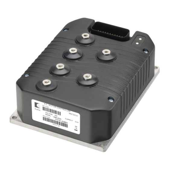
FIGURES / TABLES FIGURES . 1: Curtis 1298 controller.............. 1 . 2: Mounting dimensions, Curtis 1298 controller ......3 . 3: Basic wiring diagram .............. 10 . 4: Wiring for Type 1 throttles ............ 12 . 5: Wiring for Type 2 throttles ............ 13 . -
Page 5: Overview
Curtis 1298 integrated traction and hydraulic system motor controller. Like all Curtis controllers, the 1298 offers superior operator control of motor drive performance. Features include: ✓ High efficiency, field-oriented motor control algorithms ✓ Advanced Pulse Width Modulation technology for efficient use... - Page 6 Note: If you have a dual-drive application, see the Dual Drive Addendum to the 1298 manual, part number 38272-DD. Familiarity with your Curtis controller will help you install and operate it prop- erly. We encourage you to read this manual carefully. If you have questions, please contact the Curtis office nearest you.
-
Page 7: Installation And Wiring
INSTALLATION AND WIRING MOUNTING THE CONTROLLER The outline and mounting hole dimensions for the 1298 controller are shown in Figure 2. This controller meets the IP65 requirements for environmental protection against dust and water. Nevertheless, in order to prevent external corrosion and leakage paths from developing, the mounting location should be carefully chosen to keep the controller as clean and dry as possible. - Page 8 Wear safety glasses, and use properly insulated tools to prevent shorts. — Charging or discharging generates hydrogen gas, LEAD ACID BATTERIES which can build up in and around the batteries. Follow the battery man- ufacturer’s safety recommendations. Wear safety glasses. Curtis 1298 Manual,...
-
Page 9: Table 1: High Current Connections
With multiple high current controllers, use a star ground from the battery terminal. Pump wiring (PUMP) Cable lengths should be kept as short as possible. Use high quality copper lugs and observe the recommended torque ratings. For best noise immunity the motor Curtis 1298 Manual,... - Page 10 All other low current wiring The remaining low current wiring should be run according to standard practices. Running low current wiring next to high current wiring should always be avoided. Curtis 1298 Manual,...
-
Page 11: Table 2: Low Current Connections
10 Switch 4 Generic switch input #4. Sw_4 * The related VCL columns are vital when writing VCL code (see Section 7). VCL “functions” are used to access the various I/Os; VCL “references” are predefined names for specific pins. Curtis 1298 Manual,... - Page 12 #1 or as Analog1_Input generic analog input #1. Typically used for emergency reverse switch (if applicable). 25 +12V Out Unregulated low power Ext_Supply_Current +12V output. 26 +5V Out Regulated low power 5_Volts_Output +5V output. Ext_Supply_Current Curtis 1298 Manual,...
- Page 13 B. MotorspeedB 33 Switch 8 Generic switch input #8. Sw_8 Typically used as the Reverse switch. 34 CAN Term L Low connection for the CAN bus termination jumper. 35 CANL CAN bus low. Setup_CAN Setup_Mailbox Send_Mailbox etc. Curtis 1298 Manual,...
-
Page 14: Fig . 3: Basic Wiring Diagram
The main contactor coil must be wired directly to the controller as shown in Figure 3 to meet EEC safety requirements. The controller can be programmed to check for welded or missing contactor faults and uses the main contactor Fig. 3 Basic wiring diagram, Curtis 1298 motor controller. Curtis 1298 Manual,... -
Page 15: Switch Input Wiring
Switch 8: Reverse input if Throttle Type = 1–3 (see page 39). THROTTLE WIRING Various throttles can be used with the 1298 controller. They are characterized as one of five types in the programming menu of the 1311 programmer. Type 1: 2-wire 5kΩ–0 potentiometers... -
Page 16: Fig . 4: Wiring For Type 1 Throttles
Wiring for the most common throttles is described in the following text and shown in the accompanying illustrations. If a throttle you are planning to use is not covered, contact the Curtis office nearest you. Throttle Type 1 For these 2-wire resistive potentiometers, shown in Figure 4, full throttle request corresponds to 0 Ω... -
Page 17: Fig . 5: Wiring For Type 2 Throttles
2 — INSTALLATION & WIRING: Throttle Wiring Fig. 5 Wiring for Type 2 Voltage Source throttles. Current Source 3-wire Potentiometer Curtis ET-XXX Electronic Throttle Curtis 1298 Manual,... -
Page 18: Fig . 6: Wiring For Type 3 Throttles
VCL variables VCL_Throttle and VCL_Hyd_Throttle. How the VCL program is written will determine where the throttle signal originates from, making this a very flexible throttle input method. VCL can be written to use the throttle Curtis 1298 Manual,... - Page 19 CAN communication messages as the source of the throttle signals. If you have questions regarding this throttle type, contact the Curtis office nearest you. Setting the Throttle Type to Type 5 also allows the throttle inputs to be redefined by a VCL program for uses other than as throttle inputs.
- Page 20 Above 10 V= Driver 2 1.5 V min 150 kΩ Driver 3 Driver 4 Prop Driver “MaxV” in this and the following tables is the controller’s maximum voltage: 30 V for 24V models, and 45 V for 24–36V models. Curtis 1298 Manual,...
- Page 21 When the parameter PD Enable = On, the PD driver is current controlled and thus is not affected by the overcurrent limitations which means a full range of 0–100% PWM is allowed on this PD driver output. Curtis 1298 Manual,...
- Page 22 CURRENT VOLTAGE TOLERANCE +12V Out 11.5 to 14.5 V 200 mA max -1 V to ±8 kV (air +5V Out 5 V ±5% (combined total) (MaxV + 10 V) discharge) I/O Ground 500 mA max not protected Curtis 1298 Manual,...
- Page 23 0 to 6.25 V 290 kΩ 0.76 mA Pot2 Wiper (voltage nominal and 3-wire) (source, 2-wire) Pot Low 0 to 10 V 20 Ω nom. Faults if -1 V to above (MaxV + 10 V) 11 mA (sink) Curtis 1298 Manual,...
- Page 24 The Curtis 1311 handheld programmer plugs into a connector wired to pins 28 and 29, along with ground (pin 7) and the +12V power supply (pin 25); see wiring diagram, Figure 3. The Curtis Model 840 display can plug into the same 4-pin connector.
-
Page 25: Programmable Parameters
PROGRAMMABLE PARAMETERS These controllers have a number of parameters that can be programmed using a Curtis 1311 handheld programmer or 1314 Programming Station. The pro- grammable parameters allow the vehicle’s performance to be customized to fit the needs of specific applications. -
Page 26: Table 3: Programmable Parameter Menus
—LS (Low Speed) BRAKE MENU * —Reversal Soften The Brake menu is not typically —Max Speed Accel applicable to 1298 controllers. If —Max Speed Decel you will be using these parameters in your application, refer to the 1234/36/38 manual. Curtis 1298 Manual,... - Page 27 —Field Weakening Control ..p. 62 —User Undervoltage —FW Base Speed —Reset Volts Per Cell —Field Weakening —Full Volts Per Cell —Weakening Rate —Empty Volts Per Cell —Motor Type ..... p. 62 —Discharge Time —BDI Reset Percent Curtis 1298 Manual,...
- Page 28 8 available bits. Within the menu charts, each pair of bit variable names is shown as a grouped set, with the bit name appearing first and then the byte name: Metric Units On/Off Metric_Units On/Off OptionBits3 [Bit 5] Curtis 1298 Manual,...
- Page 29 SPEED MODE EXPRESS SPEED MODE TORQUE MODE Contact Curtis if you are interested in a custom control method. Note: Do not change this parameter while the controller is powering the motor. Any time this parameter is changed a Parameter Change Fault (fault code 49) is set and must be cleared by cycling power;...
- Page 30 This parameter should be programmed On to operate a pump motor AC_Pump_Enable_SpdM On/Off rather than a vehicle drive motor. Speed controller responsiveness and AC_Pump_Enable_SpdM_Bit0 [Bit 0] stability are enhanced, and the motor is allowed to turn only in the forward direction. Curtis 1298 Manual,...
- Page 31 (i.e., setting it to a higher value) will soften the feel. It should be set fast enough (i.e., at a low enough value) to prevent the vehicle from running on after throttle release. Curtis 1298 Manual,...
- Page 32 Release Rate 0.1–2.0 sec Determines how fast the Kaff and Kbff terms release. It should be set fast Acc_FF_Release_Rate_SpdM 100–2000 enough (i.e., at a low enough value) to prevent the vehicle from running on after throttle release. Curtis 1298 Manual,...
-
Page 33: Fig . 7: Acceleration Response Rate Diagram
Fig. 7 Acceleration response rate diagram. In this example, HS = 70%, LS = 30%, Typ Max Spd = 5000 rpm. Curtis 1298 Manual,... -
Page 34: Fig . 8: Braking Response Rate Diagram
5.0 * (4500–2500) / 5000 = 2.0 seconds to ramp from 4500 rpm to 2500 rpm. Fig. 8 Braking response rate diagram. In this example, HS = 70%, LS = 30%, Typ Max Spd = 5000 rpm. Curtis 1298 Manual,... - Page 35 Provides damping as the vehicle approaches top speed, thereby reducing Kd_TrqM 0–8192 overshoot. If Kd is set too high, the vehicle may take too long to reach top speed. If Kd is set too low, the vehicle may overshoot top speed, especially when traveling downhill. Curtis 1298 Manual,...
- Page 36 In the negative direction, the restraint current is linearly increased from the Creep Torque current at zero rpm motor speed to the restraint current at the Neutral Taper Speed. Note: Setting the taper speed too low may cause oscillations in the motor. Curtis 1298 Manual,...
- Page 37 For example, suppose you change Max Speed from 3000 rpm to 1000 rpm. If Typical Max Speed is 5000 rpm, and the rate is 5.0 sec- onds, it will take 5.0 * (3000–1000) / 5000 = 2.0 seconds to ramp from 3000 rpm to 1000 rpm. Curtis 1298 Manual,...
-
Page 38: Fig . 9: Throttle Mapping, Torque Control Mode
3 — PROGRAMMABLE PARAMETERS: Fine Tuning Parameters (TORQUE CONTROL MODE) Fig. 9 Throttle mapping (torque control mode). Fig. 10 Effect of Gear Soften parameter (torque control mode). TIME Fig. 11 Effect of Brake Taper Speed parameter (torque control mode). Curtis 1298 Manual,... - Page 39 This parameter appears twice in the menu structure. For description, Set_Speed_Settling_Time 0–156 see EM Brake Control menu, page 43. Set Speed Threshold 5–100 rpm This parameter appears twice in the menu structure. For description, Set_Speed_Threshold 5–100 see EM Brake Control menu, page 43. Curtis 1298 Manual,...
- Page 40 Sets the maximum current the controller will supply to the pump motor DC_Pump_Current_Limit 1638–32767 during lift operation, as a percentage of the controller’s full rated current. The full rated current depends on the controller model; see specifications in Table D-1 for the rated current of your model. Curtis 1298 Manual,...
-
Page 41: Fig . 12: Drive Current Limiting Map
Plus 4xDelta 0–100 % Sets heating. It can also be used to keep consistent vehicle power PL_Drive_Nominal_Plus_4xDelta 0–32767 with changing battery state-of-charge. Plus 8xDelta 0–100 % Sets PL_Drive_Nominal_Plus_8xDelta 0–32767 Fig. 12 Drive current limiting map (typical example). Curtis 1298 Manual,... -
Page 42: Fig . 13: Regen Current Limiting Map
One possible use is to compensate for the torque-speed characteristic of the motor. Plus 4xDelta 0–100 % Sets Nominal 0–32767 PL_Regen_ _Plus_4xDelta Plus 8xDelta 0–100 % Sets Nominal 0–32767 PL_Regen_ _Plus_8xDelta Fig. 13 Regen current limiting map (two examples). Curtis 1298 Manual,... - Page 43 THROTTLE MENU ALLOWABLE PARAMETER RANGE DESCRIPTION Throttle Type 1–5 The 1298 controller accepts a variety of throttle inputs. The throttle Throttle_Type 1–5 type parameter can be programmed as follows: 2-wire rheostat, 5kΩ–0 input single-ended 3-wire 1kΩ–10kΩ potentiometer, or 0–5V voltage source 2-wire rheostat, 0–5kΩ...
- Page 44 Together these four generic parameters determine the controller’s response to throttle demand (in forward or reverse) and to brake demand. In the examples shown in this figure, Deadband = 0.5V Max = 4.5V Offset = 0. Curtis 1298 Manual,...
- Page 45 (see Figure 17, page 93) will require VCL_Throttle_Enable_Bit0 [Bit 0] VCL to define the connection between the OS_Throttle and VCL_Throttle variables. This allows VCL flexibility and customization of throttle processing, while still allowing Throttle_Type 1–4 with throttle fault detection. Curtis 1298 Manual,...
- Page 46 40V. If Battery Voltage Compensated = On, the output will still be 36V (Nominal Voltage × Holding Voltage) to the coil. If Battery Voltage Compensated = Off, the output will be 30V (Actual Voltage × Holding Volt- age) to the coil. Curtis 1298 Manual,...
- Page 47 The purpose of this delay is to prevent the vehicle from lunging forward if it is unloaded on a hill such that the torque measured by position-hold is no longer valid. Note: This parameter is applicable only when Torque Preload Enable = On (see conditions above). Curtis 1298 Manual,...
- Page 48 Compensated = Off, the output will be 30V (Actual Voltage × Holding Volt- age) to the coil. Interlock Type 0–2 Three interlock options are available: Interlock_Type 0–2 0 = interlock turns on with switch 3. 1 = interlock controlled by VCL functions. 2 = interlock turns on with KSI. Curtis 1298 Manual,...
- Page 49 Precharge_Enable On/Off current charge of the controller’s internal capacitor bank before the main OptionBits2 [Bit 6] contactor is closed. This decreases the arcing that would otherwise occur when the contactor is closed with the capacitor bank discharged. Curtis 1298 Manual,...
- Page 50 Higher gains force the control loop to respond quickly but may cause oscillations. These parameter descriptions assume the proportional driver is being used to drive a proportional valve, and that the PD current control software is active (PD_Enable = On). Curtis 1298 Manual,...
- Page 51 External Supply Min 5–200 mA Sets the lower threshold of the combined current of the 5V and 12V External_Supply_Min 52–800 external supplies. At or below this threshold a fault will be created that can be read by VCL. Curtis 1298 Manual,...
- Page 52 (fault code 49) is set and must be cleared by cycling power; this protects the controller and the operator. ☞ Adjusting this parameter can be hazardous; setting it improperly may cause vehicle malfunction, including uncommanded drive. For instructions, see Section 5, Step (page 75). Curtis 1298 Manual,...
- Page 53 Type 4 2× Type 3, in series Type 5 PT1000. Custom sensor types can be set up easily, if none of the five predefined types is appropriate for your application. Please contact your Curtis customer support engineer. ☞ Note: The industry standard KTY temperature sensors are silicon temperature sensors with a polarity band;...
-
Page 54: Fig . 15: Hydraulic System Diagram
Hydraulic Parameters HYDRAULIC OPERATION The 1298 controls the speed of the pump motor, and also the valves on the Lift cylinder’s hydraulic line. By so doing, it controls the hydraulic path for Lift and Lower operations. The hydraulic path for any other hydraulic operations (e.g., reach, tilt, sideshift, rotate) is provided by the vehicle manufacturer, with the 1298 controlling the pump motor speed. - Page 55 The load hold valve is either open or shut, which means it closes abruptly. To prevent jitter it is important that the delay time be set long enough for the hydraulic fluid to stop flowing before the load hold valve snaps shut. Curtis 1298 Manual,...
- Page 56 1 = Hydraulic inhibit enabled for lift (pump) operation and disabled for lowering operation. 2 = Hydraulic inhibit enabled for lowering operation and disabled for lift (pump) operation. 3 = Hydraulic inhibit enabled for both lift (pump) and lowering operation. Curtis 1298 Manual,...
- Page 57 ALLOWABLE PARAMETER RANGE DESCRIPTION Hyd Throttle Type 1–5 The 1298 controller accepts a variety of throttle inputs. The hydraulic Hyd_Throttle_Type 1–5 throttle type parameter can be programmed as follows: 2-wire rheostat, 5kΩ–0 input single-ended 3-wire 1kΩ–10kΩ potentiometer, or 0–5V voltage source 2-wire rheostat, 0–5kΩ...
- Page 58 However, in order to “combine the best of both worlds,” you must write VCL code to define the connection between the OS_Hyd_Throttle and VCL_Hyd_Throttle variables. This combination allows VCL flexibility and customization of hydraulic throttle processing, while still allowing hydraulic types 1–4 with their automatic throttle fault detection. Curtis 1298 Manual,...
- Page 59 48–80V controller being used in a system with a 48V battery pack. In this case, the overvoltage threshold can be raised by setting the User Overvoltage to a higher value. The overvoltage threshold can never be raised above the controller’s power base maximum voltage rating. Curtis 1298 Manual,...
- Page 60 Reset Volts Per Cell 2.09 2.09 Full Volts Per Cell 2.04 2.04 Empty Volts Per Cell 1.73 1.90 Use the standard values for your type of batteries as the starting point in setting the reset, full, and empty volts-per-cell parameters. Curtis 1298 Manual,...
- Page 61 Percentage < BDI Reset Percent)). * To determine the number of cells in your battery pack, divide your Nominal Voltage setting (page 55) by 2. DUAL DRIVE MENU FOR DUAL DRIVE PARAMETERS, SEE THE DUAL DRIVE ADDENDUM, P/N 38272-DD. Curtis 1298 Manual,...
- Page 62 Capture Distance 3 1–1320 This parameter allows a third capture distance to be defined, and works Capture_Distance_3 1–1320 identically to Capture Distance 1. The result is stored as “Time to Dist 3” in » the Monitor Vehicle menu. Curtis 1298 Manual,...
- Page 63 If the vehicle is already traveling in the reverse direction above the EMR Speed, the EMR Decel Rate will bring the vehicle down to the EMR Speed. Curtis 1298 Manual,...
- Page 64 EM brake to reduce stopping distance. If Interlock Brake Timeout expires and the motor is still moving, regen braking will continue to retard vehicle motion in conjunction with the EM brake. Note: This parameter is only applicable when EM_Brake_Type = 1 or 2 (see page 42). Curtis 1298 Manual,...
- Page 65 0–1 CANopen system is suppressed. Typically this is done so that the VCL program can make changes to the CANopen system before enabling it (by setting the variable Suppress_CANopen_Init = 0 and running the Setup_ CAN() function). Curtis 1298 Manual,...
- Page 66 Field Weakening Control and Motor Type Parameters MOTOR CHARACTERIZATION TESTS MENU ALLOWABLE PARAMETER RANGE DESCRIPTION Contact your Curtis customer support engineer if you will be running the AC motor characterization tests yourself. See Initial Setup, step bk, page 78. FIELD WEAKENING CONTROL MENU ALLOWABLE PARAMETER RANGE...
- Page 67 “clone” controllers with identical settings. Cloning only works between controllers with the same model number and software version. For example, the programmer can read all the information from a 1298-2205 controller and write it to other 1298-2205 controllers; however, it cannot write that same information to 1298-2206 controllers.
-
Page 68: A. Monitor Menu
0–32767 Steer Pot 0–5.5 V Voltage at steer pot wiper (pin 17) on Dual Steer_Pot_Raw 0–36044 Drive traction slave. Steer Angle -90 – 90 deg Steer angle calculated in Dual Drive Steer_Angle -90 – 90 traction master. Curtis 1298 Manual,... - Page 69 Switch 6 on or off (pin 12). Sw_6 On/Off Switches [Bit 5] Switch 7 On/Off Switch 7 on or off (pin 22). Sw_7 On/Off Switches [Bit 6] Switch 8 On/Off Switch 8 on or off (pin 33). Sw_8 On/Off Switches [Bit 7] Curtis 1298 Manual,...
- Page 70 Sw_14 On/Off Switches [Bit 13] DigOut7 Input On/Off Digital Out 7 input on or off (pin 20). Sw_15 On/Off Switches [Bit 14] Switch 16 On/Off Switch 16 on or off (pin 14). Sw_16 On/Off Switches [Bit 15] Curtis 1298 Manual,...
- Page 71 Voltage at +5V output (pin 26). Five_Volts_Output 0–1023 Ext Supply Current 5–200 mA Combined current of the external +12V and Ext_Supply_Current 52–800 +5V voltage supplies (pins 25 and 26). Pot Low 0–6.25 V Voltage at pot low (pin 18). Pot_Low_Output 0–1023 Curtis 1298 Manual,...
- Page 72 MotorspeedB 0–12000 per minute. This can be used to verify that phase B of the encoder is operating correctly. MotorSpeed B should equal MotorSpeed A in a properly operating motor encoder. MotorSpeed B does not indicate direction. Curtis 1298 Manual,...
- Page 73 4= controller overtemp cutback fault 5= controller undertemp cutback fault 6= undervoltage cutback fault 7= severe overvoltage fault 8= encoder signal not seen, or one or both channels missing 9= motor parameters out of character- ization range. Curtis 1298 Manual,...
- Page 74 0–8000 captured in the most recent acceleration. This value is used to set the Base » Speed parameter (Program Motor Control » Tuning Field Weakening Control menu), using the Base Speed set procedure described on page 62. Curtis 1298 Manual,...
- Page 75 Time taken for the vehicle to travel from Time_to_Capture_Dist_2 0–32000 zero rpm to the programmed Capture » Distance 2 (see Program Vehicle menu) during its most recent such trip. For accurate distance measurements, the Speed to RPM parameter must be set correctly (page 58). Curtis 1298 Manual,...
- Page 76 Units are decimeters or inch- es, depending on the setting of the Metric Units parameter (page 58). For accurate distance measurements, the Speed to RPM parameter must be set correctly (page 58). Curtis 1298 Manual,...
- Page 77 Mapping object for byte 5 of PDO1 MOSI. 0 – 2 Mapping object for byte 6 of PDO1 MOSI. 0 – 2 Mapping object for byte 7 of PDO1 MOSI. 0 – 2 Mapping object for byte 8 of PDO1 MOSI. Curtis 1298 Manual,...
- Page 78 DESCRIPTION Model Number 0–4294967295 Model number. For example, if you have a Model_Number 0–4294967295 controller with the model number 1298-2207, the Model Number variable will have a value of 12982207. Serial Number 0–4294967295 Serial number. For example, if the serial Serial Number 0–4294967295...
-
Page 79: Initial Setup
5 — INITIAL SETUP INITIAL SETUP The 1298 controller can be used in a variety of vehicles, which differ widely in characteristics. Before driving the vehicle, it is imperative that these initial setup procedures be carefully followed to ensure that the controller is set up to be compatible with your application. - Page 80 (room) temperature. If the 1311 does not display the correct motor temperature, contact your Curtis customer support engineer for help. If the correct motor temperature is not displayed, or if there is no motor temperature sensor, this setup procedure can continue only if the Sensor Enable is set to Off.
- Page 81 5 — INITIAL SETUP 1311 displays that the interlock is now Off. Contact your Curtis customer support engineer to resolve any issues about the interlock before continuing with the setup procedure. Once you have verified the interlock is off, you can set up the throttle input.
- Page 82 (negative Motor RPM) must be correctly selected so that when the Emergency reverse input is active the motor will rotate in the reverse direction. Contact your Curtis customer support engineer to resolve any issues about encoder direction or emergency reverse before continuing with the setup procedure.
- Page 83 = 100% through the range of motion that is considered Lift throttle max and should be = -100% through the range considered Lower throttle max. Contact your Curtis customer support engineer to resolve any issues about the throttle setup before continuing with the setup procedure.
- Page 84 If a bump is felt at the end of Lift or Lower operation, increase the Load Hold Delay value to allow the hydraulic fluid to stop flowing before the load hold valve closes. Set the Lift BDI Lockout and Hyd Inhibit Type (HPD) parameters as required by the application. Curtis 1298 Manual,...
-
Page 85: Tuning Guide
It is important that the effect of these programmable parameters be understood in order to take full advantage of the 1298’s powerful features. Please refer to the descriptions in Section 3 if there is any question about what any of the parameters do. - Page 86 42) to 1. This setting will release the EM Brake as soon as interlock is asserted. * In the Speed Mode» Response menu, set all the accel and decel rates to their fastest values (0.1 seconds); this allows better observation of the system response. Curtis 1298 Manual,...
- Page 87 The parameters in the Speed Mode» Response» Fine Tuning menu typically do not need to be changed as the default values work well in most applica- tions. Curtis 1298 Manual,...
- Page 88 The other parameters in the Torque Mode» Response» Fine Tuning menu typically may need to be changed for some applications. Read the parameter descriptions and adjust as necessary. Curtis 1298 Manual,...
-
Page 89: Vehicle Control Language
VCL than is included here. This section of the manual summarizes VCL and also describes aspects and functions of VCL that are specific to the 1298 controller. For a more complete understanding of the functions and capabilities of VCL, see the the WinVCL User’s Guide, VCL Programmer’s Guide, and VCL Common Func-... - Page 90 7 — VCL The VCL functions described in the VCL Common Functions Manual are available on 1298 controllers. The 1298 also has these additional functions: ENABLE_PRECHARGE().... p. 106 DISABLE_PRECHARGE()... p. 107 SET_DIGOUT()......p. 108 CLEAR_DIGOUT()....... p. 108 ENABLE_EMER_REV()....p. 109 DISABLE_EMER_REV()....
- Page 91 “old” value of Brake Rate will be restored from EE memory. VCL cannot write to the EE memory. The 1311 parameter settings in EE memory can be changed by using the 1311 to change the values in the program menus. Curtis 1298 Manual,...
- Page 92 I/O CONTROL WITH VCL Digital Inputs The 1298 controller has a total of 16 digital inputs. Eight are switch inputs (Sw_1 through Sw_8, plus Sw_16). These switch inputs are shown on the standard wiring diagram (Figure 3, page 10). The remaining seven digital inputs are less obvious: one on each driver and digital output (Sw_9 through Sw_15).
- Page 93 (see Figure 20, page 100) or with the VCL Put_PWM() function. The VCL statement Put_PWM(PWM5, 16383) will result in a 50% PWM output on pin 2 only if the parameter PD Enable is set to Off. See page 94 for more information on interfacing the proportional driver. Curtis 1298 Manual,...
- Page 94 DVM on the output will measure near 0 volts. Potentiometer Inputs The 1298 controller has two potentiometer inputs, which are typically used for a traction motor throttle and a pump motor throttle. Many features (map- ping, acceleration rates, etc.) are built in as 1311 parameters. Still, there are times that these potentiometer inputs may be needed for other functions such as steering angle or height sensing, or simply as data inputs.
- Page 95 VCL variables Analog1_Filtered and Analog2_Filtered. Scaling is 0–10V = 0–1023. The default filter value is 328 (10 Hz) and can be changed in VCL by changing the Analog1_Filter and Analog2_Filter values. Scaling is 0–999Hz = 0–32767. Curtis 1298 Manual,...
- Page 96 VCL variable VCL_Throttle. The VCL program manipulates the VCL_Throttle variable to get a throttle command. When the Throttle Type is set to 1–4, the variable VCL_Throttle does nothing, and the Throttle Mapping block output signal passes through. Curtis 1298 Manual,...
- Page 97 The output of the multiplying and summing nodes is a VCL variable called Mapped_Throttle, which is displayed in the 1311 Monitor» Input menu. Checking the value of Mapped_Throttle using the 1311 is a good way to see if Curtis 1298 Manual,...
- Page 98 Read Only Throttle pot value after mapping VCL_Throttle Read/Write VCL-accessible throttle command Throttle_Multiplier Read/Write Multiplies or divides the throttle signal Throttle_Offset Read/Write Provides a +/- offset to the throttle signal Throttle_Command Read Only Command resulting from throttle processing Curtis 1298 Manual,...
- Page 99 Brake Processing (Fig. 17) Braking can be programmed in the 1298 through VCL, as shown in the lower portion of Figure 17, rather than through a physical brake pot. The VCL pro- gram manipulates the VCL_Brake variable to get a brake command. Custom braking functions can be set up in this fashion;...
- Page 100 7 — VCL Fig. 18 Control Mode processing. Curtis 1298 Manual,...
- Page 101 (pin 17) is input into the controller and has the VCL vari- able name Pot2_Raw which is displayed in the 1311 Monitor» Inputs menu. The Throttle Type Processing block then combines the Hyd Throttle Type Fig. 19 Hydraulic command diagram. Curtis 1298 Manual,...
- Page 102 Hyd_Inhibit_Type parameter, and then continues in the signal chain shown in Figure 20 (page 100). For positive throttle values (following the path of the Hydraulic pump), this signal goes through a limiter that limits the max PWM according to the Curtis 1298 Manual,...
- Page 103 Hyd_Inhibit_Type parameter. The signal will be switched to zero if the main contactor has not been pulled in (Main State = 5) or if the 1298 FET bridge has not been enabled (Main State = 10 and Main Enable = Off ). The signal then continues to the Current Limit Processing block and to a final switch block...
- Page 104 Proportional driver processing. INTERFACING THE PROPORTIONAL CURRENT DRIVER In the 1298, the proportional current driver is used for the lowering valve; see Figures 15 and 16, on page 50. For other connections, VCL can directly interface the proportional current driver (PD), as shown in Figure 20. VCL can change the working parameters of the PD and can provide the command.
- Page 105 Bit6 = Controller Overtemp Cutback (Code 22) Bit7 = Controller Severe Undertemp (Code 15) Status3 Bit0 = Controller Severe Overtemp (Code 16) Bit1 = Coill Driver Open/Short (Code 31) Bit2 = Coi12 Driver Open/Short (Code 32) Bit3 = Coil3 Driver Open/Short (Code 33) Curtis 1298 Manual,...
- Page 106 Bit4 = Motor Type Fault (Code 89) Bit5 = Not Used Bit6 = Motor Characterization Fault (Code 87) Bit7 = Pump Hardware Fault (Code 97) — model 1298 controllers only Status7 Bit0 = Not Used Bit1 = VCL/OS Mismatch (Code 91)
- Page 107 VCL variables: User_Fault_Action_01 through User_Fault_Action_16. Each of the UserFault bits has a corresponding User_Fault_Action_xx variable (where “xx” is the number of the VCL fault bit). When a VCL fault bit is set, the actions defined Curtis 1298 Manual,...
- Page 108 VCL line was added (Put_Spy_Text (“BDI Low”)) to show how additional ac- tions beyond those provided in the User_Fault_Action_xx can be programmed using VCL. In this example the Put_Spy_Text(“BDI Low”) will result in the message “BDI Low” appearing on the model 840 display (presumably as a mes- Curtis 1298 Manual,...
- Page 109 VCL function Clear_Diaghist(). Also note that this example fault definition was for bit 1 of UserFault1. The VCL example set and cleared this bit by using the UserFault1.2 notation (“.2” being the mask that defines bit 1). Curtis 1298 Manual,...
- Page 110 7 — VCL ADDITIONAL VCL FUNCTIONS Function descriptions are provided here for the nine 1298 functions that are not included in the VCL Common Functions Manual. They are presented in the same format that is used in the VCL Common Functions Manual for the common functions.
- Page 111 Syntax Disable_Precharge() Parameters None. Returns 0 – Precharge not aborted. 1 – Precharge successfully aborted. Error Codes None. Example Disable_Precharge() This will attempt to abort the precharge of the capacitor bank and will clear any precharge fault. Curtis 1298 Manual,...
- Page 112 1 – Selected digital output successfully cleared. Error Codes Bad_ID is returned when DigOut_ID is not in the range of DigOut6 to DigOut7. Example Clear_Digout(DigOut6) This example will set Digital Output 6 (pin 19) Off (open circuit). Curtis 1298 Manual,...
- Page 113 Disable_Emer_Rev() function has been called, the state for emergency reverse is Off (EMR_State bit variable = Off). Syntax Disable_Emer_Rev() Parameters None. Returns 0 – Emergency reverse not disabled. 1 – Emergency reverse successfully disabled. Error Codes None. Example Disable_Emer_Rev() This will disable the emergency reverse function. Curtis 1298 Manual,...
- Page 114 Clear_Interlock() function has been called, the default state for the interlock is Off (Interlock_State bit variable = Off). Syntax Clear_Interlock() Parameters None. Returns 0 – Interlock not cleared. 1 – Interlock successfully cleared. Error Codes None. Example Clear_Interlock() This will disengage the system interlock. Curtis 1298 Manual,...
- Page 115 Setup_Pot_Faults(Pot_ID,Low_Fault,High_Fault, Fault_Value) Parameters Pot_ID identifies the throttle whose fault limits are being set: THROTTLE_POT BRAKE_POT (Note: In 1298 controllers, this is the hydraulic throttle pot.) Low_Fault Specifies the lower threshold voltage limit. Scaling: 1 V = 64 counts. High_Fault Specifies the upper threshold voltage limit.
-
Page 116: Diagnostics And Troubleshooting
(first digit) (second digit) The numerical codes used by the yellow LED are listed in the troubleshooting chart (Table 5), which also lists possible fault causes and describes the condi- tions that set and clear each fault. Curtis 1298 Manual,... -
Page 117: Table 4: Types Of Led Display
KSI and turn it back on to see if the fault clears. If it does not, shut off KSI and remove the 35-pin connector. Check the connector for corrosion or damage, clean it if necessary, and re-insert it. Curtis 1298 Manual,... -
Page 118: Table 5: Troubleshooting Chart
2. Non-controller system drain on battery. (see page 55) with FET bridge enabled. 3. Battery resistance too high. Clear: Bring capacitor voltage above 4. Battery disconnected while driving. Severe Undervoltage limit. 5. See Monitor menu » Battery: Capacitor Voltage. 6. Blown B+ fuse or main contactor did not close. Curtis 1298 Manual,... - Page 119 Set: Digital Output 6 (pin 19) current Output 6 driver (pin 19) is too low. exceeded 15 mA. Digital Output 6 driver will not turn on. Clear: Remedy the overcurrent cause and use the VCL function Set_DigOut() to turn the driver on again. Curtis 1298 Manual,...
- Page 120 Coil4 Driver Open/Short 1. Open or short on driver load. Set: Driver 4 (pin 3) is either open or 2. Dirty connector pins. shorted. ShutdownDriver4. 3. Bad crimps or faulty wiring. Clear: Correct open or short, and cycle driver. Curtis 1298 Manual,...
- Page 121 ShutdownPump 2. Pot2 wiper voltage too high. (can be changed with the VCL function (if Lift_Switch_Only_Enable=Off ); ShutdownPD Setup_Pot_Faults() (if Lower_Switch_Only_Enable=Off ) Clear: Bring Pot2 wiper voltage below the fault threshold. Curtis 1298 Manual,...
- Page 122 Hyd_Inhibit_Type parameter. when KSI was turned on. Clear: Set inputs to neutral and re-apply 2. Faulty wiring, crimps, or switches at in correct sequence. KSI, lift, lower, or hydraulic throttle inputs. 3. See Monitor menu » Inputs. Curtis 1298 Manual,...
- Page 123 (page 47). Clear: Bring the external supply current within range. OS General 1. Internal controller fault. Set: Internal controller fault detected. Clear: Cycle KSI. ShutdownMotor; ShutdownMainContactor; ShutdownEMBrake; ShutdownThrottle; ShutdownInterlock; ShutdownDriver1; ShutdownDriver2; ShutdownDriver3; ShutdownDriver4; ShutdownPD; FullBrake; ShutdownPump. Curtis 1298 Manual,...
- Page 124 KSI cycles, a check is made to verify ShutdownMainContactor; the controller. that they match and a fault issued when ShutdownEMBrake; they do not. ShutdownThrottle; Clear: Download the correct VCL and OS ShutdownInterlock; software into the controller. ShutdownDriver1; ShutdownDriver2; ShutdownDriver3; ShutdownDriver4; ShutdownPD; FullBrake; ShutdownPump. Curtis 1298 Manual,...
- Page 125 FullBrake; ShutdownPump. Illegal Model Number 1. Model_Number variable contains Set: Illegal Model_Number variable; when illegal value (not 1298, and not KSI cycles, a check is made to confirm ShutdownMotor; ShutdownMainContactor; 1234, 1236, or 1238, which are also a legal Model_Number, and a fault is ShutdownEMBrake;...
-
Page 126: Maintenance
9 — MAINTENANCE MAINTENANCE There are no user serviceable parts in Curtis 1298 controllers. No attempt should be made to open, repair, or otherwise modify the controller. Doing so may damage the controller and will void the warranty. It is recommended that the controller and connections be kept clean and dry and that the controller’s fault history file be checked and cleared periodi-... - Page 127 APPENDIX A THEORY OF OPERATION Curtis 1298 controllers convert DC battery power to 3-phase AC power by precisely controlling the induction drive for high bandwidth, high efficiency, and low ripple torque generation. To realize this level of precise torque control of...
- Page 128 Figure A-2. Each half-bridge power stage is a parallel array of high-side and low-side power MOSFETs mounted to Insulated Metal Substrate (IMS) circuit board. This technology provides a very low thermal resistance to the heatsink and enables high power capability in a compact area. Curtis 1298 Manual, os11...
- Page 129 U and V motor output busbars where they pass through the capacitor board on their way to the external motor connections. Motor speed and direc- tion are simultaneously sensed by a quadrature-type speed encoder mounted on the motor shaft. Curtis 1298 Manual, os11...
- Page 130 Signals with high frequency content can produce significant emissions if con- nected to a large enough radiating area (created by long wires spaced far apart). Contactor drivers and the motor drive output from Curtis controllers can contribute to RF emissions. Both types of output are pulse width modulated square waves with fast rise and fall times that are rich in harmonics.
- Page 131 field. This coupling can be reduced by placing the controller as far as possible from the noise source or by enclosing the controller in a metal box. Some Curtis controllers are enclosed by a heatsink that also provides shielding around the controller circuitry, while others are partially shielded or unshielded.
- Page 132 ELECTROSTATIC DISCHARGE (ESD) Curtis motor controllers contain ESD-sensitive components, and it is therefore necessary to protect them from ESD (electrostatic discharge) damage. Most of these control lines have protection for moderate ESD events, but must be protected from damage if higher levels exist in a particular application.
- Page 133 The requirement to mark equipment with the WEEE symbol (the crossed-out wheeled bin) went into effect as of August 13, 2005. As of this date, Curtis In- struments began the process of marking all products that fall within scope of this directive with the WEEE symbol, as shown opposite.
- Page 134 Curtis firmly believes that the operating environments, safety requirements, and reliability levels required of automotive electronics are directly analogous to that of our speed controller products. As such, Curtis will not be switching to a lead-free solder process until lead-free solder pastes and techniques are available that meet the requirements of the RoHS study groups and ELV Automotive In- dustry bodies.
- Page 135 PROGRAMMING DEVICES Curtis programmers provide programming, diagnostic, and test capabilities for the 1298 controller. The power for operating the programmer is supplied by the host controller via a 4-pin connector. When the programmer powers up, it gathers information from the controller.
- Page 136 85°C. No addtitional external heatsink is used for the 2-minute rating test. 1-hour ratings assume that only one motor (traction or pump) is running for the test. For a combined rating, contact your Curtis customer support engineer for power dissipation charts. Curtis 1298 Manual,...
Need help?
Do you have a question about the 1298 and is the answer not in the manual?
Questions and answers