Table of Contents
Advertisement
Quick Links
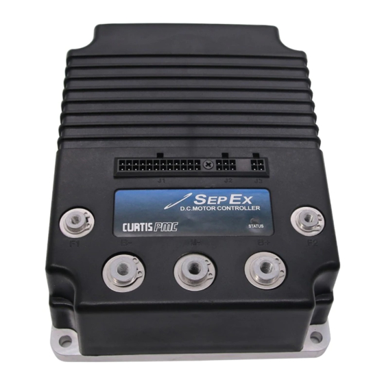
Curtis
This sheet is provided to aid in the installation of your remanufactured CURTIS controller.
Upon installation, you may encounter problems that may, or may not, be due to a faulty
controller. The following steps must be taken to help diagnose a possible cart fault or faulty
controller. An analog or digital volt ohm meter (VOM) will be needed to perform these checks.
If These Steps are Not Performed Before Installing The Control
CHECK MOTOR WINDINGS:
Set your VOM to RESISTANCE (Ω).
To test the resistance of VOM leads, please touch the meter leads together.
Subtract this measurement from each test below to get your true measurement.
With motor disconnected, measure A1 to A2. This should measure approximately BETWEEN .2Ω and 2Ω.
With motor disconnected, measure F1 to F2. This should measure approximately BETWEEN .8Ω and 3Ω.
With motor disconnected, measure A1 to F1. This should measure OPEN.
With motor disconnected, measure F1 to motor case. This should measure greater than 5MΩ.
CHECK MAIN SOLENOID:
Disconnect all wires from the main solenoid.
Set your VOM to RESISTANCE (Ω).
Measure the solenoid coil. This should measure 100Ω - 250Ω (depending on solenoid type).
Connect VOM leads to the main solenoid lugs.
Attach jumpers from main battery positive and negative to the coil (small terminals).
Meter should jump from infinity to LESS THAN .3Ω.
Remove jumpers and reconnect solenoid wiring from the harness. (If suppression diode is present,
the non-banded side must go to the wire from J1 pin 17 from the controller. Be sure to check diode
functionality with VOM prior to install. If pre-charge resister is installed, please remove. This control is
equipped with an internal resistor, and installing one on the solenoid could cause damage to the control.)
CHECK THE CART WIRE HARNESS:
Check the connectors on the wire harness for corrosion, loose, broken, burnt or missing pins.
Repair or replace pins as necessary.
IF ANY OF THE ABOVE ITEMS ARE NOT WITHIN THE SPECIFIED RANGES THE CONTROLLER WILL FAIL.
THESE ITEMS MUST BE CORRECTED BEFORE THE CONTROLLER IS INSTALLED OR WARRANTY WILL BE VOID.
It is recommended to replace your solenoid at the time of controller replacement. FSIP now stocks popular replacement White Rodgers solenoids for your convenience.
1268-5403
WARRANTY WILL BE VOID
STEPS TO PERFORM BEFORE CONTROL INSTALLATION
Generic Golf (1268-5403) Install Sheet-370 Rev 01 05/25/18
Sheet 1 of 6
Advertisement
Table of Contents
Troubleshooting

Related Manuals for Curtis 1268-5403


Summary of Contents for Curtis 1268-5403
- Page 1 Curtis 1268-5403 This sheet is provided to aid in the installation of your remanufactured CURTIS controller. Upon installation, you may encounter problems that may, or may not, be due to a faulty controller. The following steps must be taken to help diagnose a possible cart fault or faulty controller.
- Page 2 (Pedal Switch In) J1-19 (Backup Alarm Out) Reverse Alarm Pin 4 Pin 3 Pin 13 Diagram shows the back (wire) side of controller connector Pin 1 Pin 1 Pin 1 Sheet 2 of 6 Generic Golf (1268-5403) Install Sheet-370 Rev 01 05/25/18...
- Page 3 Pin J1-13 (If no wire in this position then skip step, otherwise) must equal approximately 5 volts If not approximately 5 volts, check connector and wire terminal for being burnt/corroded. If terminal is clean, controller may be defective Continued on next page … Sheet 3 of 6 Generic Golf (1268-5403) Install Sheet-370 Rev 01 05/25/18...
- Page 4 Status LED on top of the controller. If not toggling between approximately 0 and 2 volts, check wiring and remote LED for an open condition Continued on next page … Sheet 4 of 6 Generic Golf (1268-5403) Install Sheet-370 Rev 01 05/25/18...
- Page 5 1. Aux relay missing or wire to coil open WELDED AUX RELAY Welded aux relay 1. Aux relay stuck closed 2. Aux relay shorted Continued on next page … Sheet 5 of 6 Generic Golf (1268-5403) Install Sheet-370 Rev 01 05/25/18...
- Page 6 Technical Support options … Troubleshooting Manuals / Codes www.fsip.biz/TroubleshootingManuals.html Live Tech Support Chat www.fsip.biz Technical Support Forum fsip.websitetoolbox.com Frequently Asked Questions www.fsip.biz/FAQ.html Phone Support 1-800-333-1194 (Option 4) Sheet 6 of 6 Generic Golf (1268-5403) Install Sheet-370 Rev 01 05/25/18...
Need help?
Do you have a question about the 1268-5403 and is the answer not in the manual?
Questions and answers