Table of Contents
Advertisement
Manual
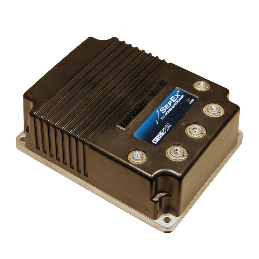
Model 1244
MultiMode™ Electronic Motor Controller
Read Instructions Carefully!
Specifications are subject to change without notice.
© 2013 Curtis Instruments, Inc. ® Curtis is a registered trademark of Curtis Instruments, Inc.
© The design and appearance of the products depicted herein are the copyright of Curtis Instruments, Inc.
Curtis Instruments, Inc.
200 Kisco Avenue
Mt. Kisco, NY 10549
www.curtisinstruments.com
16958 Rev E 10/2013
Advertisement
Table of Contents
Troubleshooting

Related Manuals for Curtis 1244


Summary of Contents for Curtis 1244
- Page 1 Specifications are subject to change without notice. © 2013 Curtis Instruments, Inc. ® Curtis is a registered trademark of Curtis Instruments, Inc. © The design and appearance of the products depicted herein are the copyright of Curtis Instruments, Inc. 16958 Rev E 10/2013...
-
Page 3: Table Of Contents
Drive Current Limit, M1–M4 ..........36 Braking Current Limit, M1–M4 ..........36 Minimum Field Current Limit ..........36 Maximum Field Current Limit ..........37 Restraint ..................37 Emergency Reverse Current Limit ........... 38 Current Ratio ................38 Curtis 1244 Manual, Rev. E... - Page 4 Equalizing loaded and unloaded vehicle speed ......60 Fine Tuning ..................62 Response to increased throttle ..........62 Response to reduced throttle ............ 63 Smoothness of direction transitions ......... 63 Ramp climbing ...............65 Ramp restraint ................66 Curtis 1244 Manual, Rev. E...
- Page 5 Programmer Diagnostics ..............72 LED Diagnostics ................74 Fault Output Drivers ..............75 MAINTENANCE ................76 Cleaning ..................76 Diagnostic History .................76 appendix a Glossary of Features and Functions appendix b Programming Devices appendix c Specifications, 1244 Controller Curtis 1244 Manual, Rev. E...
- Page 6 Wiring for 3-wire potentiometer throttle (“Type 2”) ....13 fig. 8: Wiring for current source throttle (“Type 2”) ......13 fig. 9: Wiring for Curtis ET-XXX electronic throttle (“Type 2”) ..14 fig. 10: Wiring for 0–5kΩ throttle (“Type 3”) ........15 fig. 11: Wiring for fault outputs ............16...
-
Page 7: Overview
The 1244 controller can also be specified to be compatible with CAN Bus communication systems. - Page 8 1 — OVERVIEW Like all Curtis motor controllers, the 1244 offers superior operator control of the vehicle’s motor drive speed. Features include: ✓ Full-bridge field and half-bridge armature power MOSFET design, providing • infinitely variable forward, reverse, drive, and brake control • silent high frequency operation • high efficiency ✓ Regenerative braking, providing longer operation on a single battery charge and reducing motor brush wear and motor heating ✓...
- Page 9 ✓ Can be configured for CAN Bus compatibility. Familiarity with your Curtis controller will help you install and operate it properly. We encourage you to read this manual carefully. If you have questions, please contact the Curtis office nearest you.
-
Page 10: Installation And Wiring
Controller INSTALLATION AND WIRINg MOUNTINg THE CONTROLLER The outline and mounting hole dimensions for the 1244 controller are shown in Figure 2. The controller can be oriented in any position, and meets the IP64/IP67 ratings for environmental protection against dust and water. However, the lo- cation should be carefully chosen to keep the controller as clean and dry as possible.When selecting the mounting position, be sure to also take into... - Page 11 — Charging or discharging generates hydrogen gas, lead acid batteries which can build up in and around the batteries. Follow the battery man- ufacturer’s safety recommendations. Wear safety glasses. Curtis 1244 Manual, Rev. E...
-
Page 12: Connections: Low Current
2 — INSTALLATION & WIRING: Controller CONNECTIONS Low Current Connections Three low current connectors are built into the 1244 controller. They are located in a row on the top of the controller: 24-pin 6-pin 4-pin The 24-pin connector provides the logic control connections. The mating connector is a 24-pin Molex Mini-Fit Jr. -
Page 13: Connections: High Current
The L and H terminations provide a 120Ω termination impedance for the CAN H I/O and CAN L I/O inputs if necessary. Refer to the Curtis CAN Protocol Document to determine the proper termination for a given application. -
Page 14: Fig. 3: Standard Wiring Configuration
MAIN CONTACTOR COIL FORWARD REVERSE 5 kΩ–0 THROTTLE (TYPICAL) MODE SELECT 2 MODE SELECT 1 INTERLOCK KEYSWITCH MAIN POLARITY CONTACTOR PROTECTION DIODE POWER CONTROL FUSE FUSE Fig. 3 Standard wiring configuration, Curtis 1244 controller. Curtis 1244 Manual, Rev. E... - Page 15 Pin 17, the controller will not be able to open the main contactor in serious fault conditions and the system will therefore not meet eec safety requirements. Curtis 1244 Manual, Rev. E...
-
Page 16: Wiring: Throttle
2 — INSTALLATION & WIRING: Throttle WIRINg: Throttle Various throttles can be used with the 1244 controller. They are categorized as one of five types in the programming menu of the handheld programmer. Type 1: two-wire 5kΩ–0 throttles Type 2: 0–5V throttles, current source throttles, three-wire potentiometer throttles, and electronic throttles—wired for single-ended operation... -
Page 17: Fig. 4: Wiring For 5Kω-0 Throttle ("Type 1")
Wiring for various throttles is described below. note: In the text, throttles are identified by their nominal range and not by their actual operating range. If the throttle you are planning to use is not covered, contact the Curtis office nearest you. -
Page 18: Fig. 6: Wiring For 0-5V Throttle ("Type 2")
Throttle Max), measured relative to B-. Fig. 6 Wiring for (a) Sensor-referenced 0–5V throttles (“Type 2”). 0–5V throttle PIN KEY 0–5V Input Pin 15 Pot Low Pin 14 SENSOR GROUND (b) Ground-referenced 0–5V throttle PIN KEY 0–5V Input Pin 15 Curtis 1244 Manual, Rev. E... -
Page 19: Fig. 7 Wiring For 3-Wire Potentiometer Throttle ("Type 2")
The 3-wire potentiometer is used in its voltage divider mode, with the voltage source and return being provided by the 1244 controller. Pot High (Pin 13) provides a current limited 5V source to the pot, and Pot Low (Pin 14) provides the return path. -
Page 20: Fig. 9 Wiring For Curtis Et-Xxx Electronic Throttle ("Type 2")
2 — INSTALLATION & WIRING: Throttle Curtis ET-XXX Electronic Throttle The Curtis ET-XXX provides a 0–5V throttle and forward/reverse inputs for the 1244 controller. Wiring for the ET-XXX is shown in Figure 9. Fig. 9 Wiring for Curtis ET-XXX electronic throttle (“Type 2”). -
Page 21: Fig. 10: Wiring For 0-5Kω Throttle ("Type 3")
With a Type 4 throttle, no direction signals to the controllers’ forward and reverse inputs are required. Direction is determined by the wiper input value. The throttle interface to the controller is similar to that for Type 2 throttles. Curtis 1244 Manual, Rev. E... -
Page 22: Can-Nodes Throttle ("Type 5")
CAN Bus architecture. WIRING: Fault Outputs The 1244 controller has two fault output drivers, at Pin 5 and Pin 6, which can be used to provide diagnostic information either to a display panel on the vehicle or to a remote location. These outputs are rated at 10mA maximum current at the nominal battery pack voltage. - Page 23 The output will be pulse-width-modulated at the coil holding voltage along with the main, auxiliary, and electromagnetic brake contactor drivers, if the holding voltage parameter is set to less than 100%. Curtis 1244 Manual, Rev. E...
-
Page 24: Fig. 12: Wiring For Main And Auxiliary Contactor Coils When Using The Interlock And Dropout Delay Features
PWM output de- celerates to zero. The output will be pulse-width-modulated at the coil holding voltage along with the main, auxiliary, and reverse signal contactor drivers, if the holding voltage parameter is set to less than 100%. Curtis 1244 Manual, Rev. E... -
Page 25: Wiring: Pedal Switch
Refer to the Curtis CAN Protocol Document for information about the CAN Bus interface. WIRING: Emergency Reverse If you are installing a 1244 controller in a walkie vehicle, the emergency reverse switch should be wired to Pin 7, as shown in Figure 13. Fig. 13... - Page 26 The emergency reverse wiring check wire (see dotted line in Figure 13) should be connected to the emergency reverse switch terminals and to Pin 22. For information about the emergency reverse parameters, see Section 3: Programmable Parameters. Curtis 1244 Manual, Rev. E...
-
Page 27: Contactor, Switches, And Other Hardware
CONTACTOR, SWITCHES, and OTHER HARDWARE Main Contactor A main contactor is recommended for use with any 1244 controller. A main contactor allows the controller and motor to be disconnected from the bat- tery. This provides a significant safety feature in that the battery power can be removed from the drive system if a controller or wiring fault results in battery power being applied to the motor. -
Page 28: Table 2 Mode Selection
Wiring for the mode select switches is shown in the standard wiring diagram (Figure 3, page 8). Table 2 MODE SELECTION MODE MODE OPERATING MODE SELECT SELECT SWITCH 1 SWITCH 2 MultiMode™ 1 OPEN OPEN MultiMode™ 2 CLOSED OPEN MultiMode™ 3 CLOSED OPEN MultiMode™ 4 CLOSED CLOSED Curtis 1244 Manual, Rev. E... -
Page 29: Programmable Parameters
3 — PROGRAMMABLE PARAMETERS PROGRAMMABLE PARAMETERS The 1244 controller has a number of parameters that can be programmed by means of a 1313 handheld programmer or 1314 PC Programming Station. These programmable parameters allow the vehicle’s performance characteristics to be customized to fit the needs of individual vehicles or vehicle operators. -
Page 30: Deceleration Rate
Throttle Maximum Throttle Map, M1–M4 Throttle Braking Percent, M1–M4 Current Limit Parameters Drive Current Limit, M1–M4 Braking Current Limit, M1–M4 Minimum Field Current Limit Maximum Field Current Limit Restraint Emergency Reverse Current Limit Current Ratio Curtis 1244 Manual, Rev. E... - Page 31 Reverse Signal Open Check Electromagnetic Brake Delay Electromagnetic Brake Open Check Contactor Holding Voltage Contactor Pull-In Voltage Other Parameters Battery Voltage Anti-Tiedown Sequencing Delay Pedal Interlock Emergency Reverse Enable Emergency Reverse Check Node Address Precharge Load Compensation Curtis 1244 Manual, Rev. E...
- Page 32 Quick start is adjustable from 0 to 10, in increments of 1. Increasing the value “livens” the vehicle’s acceleration response to fast throttle movements. Curtis 1244 Manual, Rev. E...
- Page 33 The regen speed parameter is adjustable from 0% to 100% of the vehicle speed, in 1% increments. Recommendations for adjusting the regen braking parameter are provided in Section 6: Vehicle Performance Adjustment. Curtis 1244 Manual, Rev. E...
- Page 34 Acceleration and deceleration characteristics of the vehicle in response to throttle changes in any of these modes will be determined by tuning parameters such as accel rate, quick start, etc. Curtis 1244 Manual, Rev. E...
-
Page 35: Table 3 Programmable Throttle Types
Throttle Parameters ThROTTLE TyPE The 1244 controller accepts a variety of throttle inputs, through various com- binations of its four throttle input pins. The most commonly used throttles can be hooked up directly: 5kΩ–0 and 0–5kΩ 2-wire rheostats, 3-wire pots, 0–5V throttles, Curtis ET-XXX electronic throttles, and CAN-Nodes based... -
Page 36: Fig. 14: Effect Of Adjusting The Neutral Deadband Parameter
Examples of deadband settings (30%, 10%, 0%) are shown in Figure 14 for throttle types 1 through 4, using a nominal 5kΩ–0 potentiometer. (For throttle type 5, see the Curtis CAN Protocol Document.) Fig. 14 Effect of 5kΩ–0 Throttle: Type 1... - Page 37 0% to 30%, in 2% increments. The default deadband setting is 10%. The nominal throttle wiper voltage range depends on the throttle type selected. See Table 1 (page 10) for the characteristics of your selected throttle type. Curtis 1244 Manual, Rev. E...
-
Page 38: Fig. 15: Effect Of Adjusting The Throttle Max Parameter
30% Deadband 4.5V 2.0V 90% Throttle Max 10% Deadband 0.2V 4.5V 60% Throttle Max 10% Deadband 0.2V 3.0V 0–5kΩ Throttle: Type 3 100% Throttle Max 30% Deadband 3.3V 1.2V (5.0kΩ) (1.4kΩ) Curtis 1244 Manual, Rev. E 90% Throttle Max 30% Deadband... - Page 39 The throttle max parameter can be adjusted from 100% to 60%, in 2% increments. The nominal throttle wiper voltage range depends on the throttle type selected. See Table 1 (page 10) for the char- acteristics of your selected throttle type. Curtis 1244 Manual, Rev. E...
-
Page 40: Fig. 16: Throttle Maps For Controller With Maximum Speed Set
Controller output will begin to increase above the set creep speed as soon as the throttle is rotated out of its normal neutral range (deadband). Controller output will continue to increase, following the curve defined by the Curtis 1244 Manual, Rev. E... -
Page 41: Fig. 17: Throttle Maps For Controller With Maximum Speed Set At 80% And Creep Speed Set At 10
SPEED PARAMETERS output response to throttle Creep Speed demand. 80% Max Speed Max Speed THROTTLE PARAMETERS Deadband Throttle Max Throttle Map 40% Throttle Map (38% output at half throttle) 10% Creep Speed THROTTLE INPUT (percent) Curtis 1244 Manual, Rev. E... - Page 42 The Field Min parameter is adjustable from 2 to 20 amps, in 0.5 amp increments. Recommendations for adjusting the Field Min parameter are pro- vided in Section 6: Vehicle Performance Adjustment. Curtis 1244 Manual, Rev. E...
- Page 43 Section 6: Vehicle Performance Adjustment. RESTRAINT Because the 1244 controller is configured to provide throttle braking, overspeed will cause the controller to create a braking current and thus limit or “restrain” the overspeed condition. The restraint parameter, in combination with throttle braking percent parameter, determines how strongly the controller will attempt to limit the vehicle speed to the existing throttle setting.
- Page 44 Whether the vehicle’s loaded speed will actually increase depends on the arma- ture current being drawn at that load. If the armature current is already below the Field Map Start setting, increasing the Field Map Start value will not affect the vehicle’s loaded speed. Curtis 1244 Manual, Rev. E...
-
Page 45: Field Map
Care should be taken to ensure that excessively low Field Map values do not move the motor’s operating characteristics outside its safe commutation region. Recommendations for adjusting the Field Map parameter to achieve various performance characteristics are provided in Section 6: Vehicle Perfor- mance Adjustment Guidelines. Curtis 1244 Manual, Rev. E... -
Page 46: Fig. 19: Field Current Relative To Armature Current, With Field Map Parameter Set At 50% And 20
50% and 20%. Field Map (50%) Field Min Field Map Start Field Map Midpoint 100% ARMATURE CURRENT Field Max Field Map (20%) Field Min Field Map Start Field Map Midpoint 100% ARMATURE CURRENT Curtis 1244 Manual, Rev. E... -
Page 47: Fault Parameters
To start the vehicle, the controller must receive a direction input in addition to an interlock switch input and a KSI input before receiving a throttle input. Controller operation will be disabled immediately if throttle input is greater Curtis 1244 Manual, Rev. E... -
Page 48: Hpd Threshold
Sequencing delay (see page 47) can be used to provide a variable delay before disabling the controller, if desired. FAULT CODE The 1244 controller’s fault code drivers allow faults to be displayed in either of two different formats: Fault Code format or Fault Category format. Curtis 1244 Manual,... -
Page 49: Table 4 Fault Categories
“Off,” only the KSI input is required for the main contactor to be engaged. MAIN OPEN DLy The main contactor dropout delay parameter is applicable only if the main contactor driver interlock parameter has been set to “On.” The dropout delay Curtis 1244 Manual, Rev. E... -
Page 50: Main Coil Open Check
When this parameter is set to “On,” the controller senses the voltage at the auxiliary driver output (Pin 18) to confirm that the auxiliary contactor coil is properly connected. If Curtis 1244 Manual, Rev. E... -
Page 51: Reverse Signal Open Check
“Off.” Note: The electromagnetic brake open check parameter is applicable only if the accessory driver enable has been specified “On.” The accessory driver enable is a factory-set parameter, and is described in Section 4. Curtis 1244 Manual, Rev. E... -
Page 52: Contactor Holding Voltage
Similarly, the undervoltage threshold protects systems from operating at voltages below their design thresholds. This will ensure proper operation of all electronics whenever the vehicle is driven. The Curtis 1244 Manual, Rev. E... -
Page 53: Anti-Tiedown
This feature is useful in systems that use a seat or foot switch to guarantee operator presence for vehicle operation. Alternatively, a switch connected to the brake pedal can be configured Curtis 1244 Manual, Rev. E... -
Page 54: Emergency Reverse Enable
CAN Bus communications system. The address can be specified from 1 to 15. This parameter is valid only when the CAN Bus function has been specified for the controller; see Section 4. Curtis 1244 Manual, Rev. E... -
Page 55: Precharge
However, too much load compensation can result in jerky vehicle starts and speed oscillation (“hunting”) when the vehicle is unloaded. The load compensation parameter is adjustable from 0 to 25. Recom- mendations for adjusting this parameter are provided in Section 6: Vehicle Performance Adjustment. Curtis 1244 Manual, Rev. E... -
Page 56: Multimode™ Enable
How- ever, should the OEM prefer to offer only a single mode of operation in a given application, the MultiMode™ feature can be disabled. Each of the 1244 controller’s eight MultiMode™ parameters can be individually defined as Mul- tiMode™... -
Page 57: Can Bus Enable
On or Off OEM specifies Default setting ➤ ➤ CAN BUS ENABLE When enabled, this parameter configures the 1244 controller for use with CAN-based control systems. On or Off OEM specifies Default setting ➤ ➤... -
Page 58: Installation Checkout
LED diagnostic code in Section 8 (Diagnostics and Troubleshooting). When the problem has been corrected, it may be necessary to cycle the keyswitch in order to clear the fault. Curtis 1244 Manual, Rev. E... - Page 59 The vehicle should coast to a stop, with a fault indicated. 10. If you used a programmer, disconnect it when you have completed the checkout procedure. Curtis 1244 Manual, Rev. E...
-
Page 60: Major Tuning
6 — VEHICLE PERFORMANCE ADJUSTMENT VEHICLE PERFORMANCE ADJUSTMENT The 1244 controller is a very powerful vehicle control system. Its wide variety of adjustable parameters allow many aspects of vehicle performance to be optimized. This section provides explanations of what the major tuning parameters do and instructions on how to use these parameters to optimize the performance of your vehicle. - Page 61 8. If a bidirectional (wigwag) throttle assembly is being used, the procedure should be repeated for the reverse direction. The Throttle Deadband value should be selected such that the throttle operates correctly in both forward and reverse. Curtis 1244 Manual, Rev. E...
- Page 62 6. If a bidirectional (wigwag) throttle assembly is being used, repeat the procedure for the reverse direction. The Throttle Max value should be selected such that the throttle operates correctly in both forward and reverse. Curtis 1244 Manual, Rev. E...
-
Page 63: Tuning The Controller To The Motor
Tuning the Controller to the Motor ➁ The 1244 controller has the flexibility to be tuned to nearly any separately excited motor from any manufacturer. Parameters in the programmer’s Parame- ters Menu allow full control of the motor’s maximum armature current during driving and braking and full control of the motor’s maximum and minimum... - Page 64 The Field Min and possibly also the Field Map parameter should be increased until the indications of arcing stop. Decreasing the Field Map Start parameter will also help to move operation back into the safe commutation region. Curtis 1244 Manual, Rev. E...
-
Page 65: Setting The Unloaded Vehicle Top Speed
field current may cause overly abrupt starts; this is why we recommend using the Max Speed parameter in those cases where a moderate Field Min setting does not sufficiently reduce the vehicle top speed. Curtis 1244 Manual, Rev. E... - Page 66 ➃ The top speed of a loaded vehicle can be set to approach the unloaded top speed by tuning the 1244 controller’s Field Map Start and Load Compensation parameters. It is recommended that you review the description of the Field Map Start parameter (page 38) and Load Compensation parameter (page 49) before starting this procedure.
- Page 67 Field Map parameter will help bring the loaded speed closer to the unloaded speed. However, care must still be taken because it is possible for too low Field Map values—like too high Field Map Start values—to result in operation outside the motor’s safe commutation region. Curtis 1244 Manual, Rev. E...
-
Page 68: Fine Tuning
The Accel Rate, Max Speed, and Drive Current Limit parameters can be tuned exclusively for this precision-maneuvering mode to obtain comfortable vehicle response. Curtis 1244 Manual, Rev. E... -
Page 69: Response To Reduced Throttle
If the braking cur- rent limit is changed, evaluation and adjustment of the Throttle Braking % parameter may be necessary to obtain the response originally set in procedure ➅ . Curtis 1244 Manual, Rev. E... - Page 70 ➆ -C Low Speed vs. High Speed Braking The 1244 controller is capable of both regenerative and plug braking, and can be programmed to use one or the other as a function of vehicle speed. Plug braking provides quicker response and direction transition at low speeds, while regen braking is more powerful and efficient at high speeds.
-
Page 71: Ramp Climbing
To determine if the controller’s armature current is at its set value during ramp climbing, read the “Arm Current” in the programmer’s Test Menu. Curtis 1244 Manual, Rev. E... -
Page 72: Ramp Restraint
Therefore, the Restraint parameter should be set with both situations in mind. For tuning the vehicle’s response to reduced throttle, see tuning procedure ➅ , page 63. Curtis 1244 Manual, Rev. E... -
Page 73: Programmer Menus
T H R T L D E A D B A N D Throttle input req’d for 100% PWM, as % of 5kΩ pot T H R O T T L E M A X Curtis 1244 Manual, Rev. E... - Page 74 P E D A L I N T R L C K Precharge function: On or Off P R E C H A R G E CAN-Bus address: 1 through 15 N O D E A D D R Curtis 1244 Manual, Rev. E...
- Page 75 Type 2: SRO unless KSI + interlock inputs received before direction selected Type 3: SRO unless KSI + interlock + forward inputs received in that order Fault output types (for detail, see Section 3: Programmable Parameters, page 43) On: Fault Code format Off: Fault Category format Curtis 1244 Manual, Rev. E...
-
Page 76: Monitor Menu
C O N T R O L S T A T E Mode Select 1 switch: on/off M O D S E L 1 Mode Select 2 switch: on/off M O D S E L 2 Control states are used for diagnostic and troubleshooting purposes. Curtis 1244 Manual, Rev. E... -
Page 77: Diagnostics Menu
T H R O T T L E F A U L T 2 Other Menus The System Info Menu shows information uploaded from your 1244 controller: model number, serial number, etc. The HHP Settings Menu allows you to select the 1313 handheld programmer’s display language, adjust its display contrast,... -
Page 78: Diagnostics And Troubleshooting
8 — DIAGNOSTICS & TROUBLESHOOTING DIAGNOSTICS AND TROUBLESHOOTING The 1244 controller provides diagnostics information to assist technicians in troubleshooting drive system problems. The diagnostics information can be ob- tained by observing the appropriate display on the 1313 handheld programmer or 1314 PC Programming Station, the fault codes issued by the Status LED, or the fault display driven by the controller’s Fault 1 and Fault 2 outputs. -
Page 79: Table 5 Troubleshooting Chart
A N T I - T I E D O W N Mode 2 or Mode 4 selected at 1. Mode switches shorted to B+. startup 2. Mode switches “tied down” to select Mode 2 or Mode 4 permanently. Curtis 1244 Manual, Rev. E... -
Page 80: Led Diagnostics
8 — DIAGNOSTICS & TROUBLESHOOTING LED DIAGNOSTICS A Status LED is built into the 1244 controller. It is visible through a window in the label on top of the controller. This Status LED displays fault codes when there is a problem with the controller or with the inputs to the controller. During normal operation, with no faults present, the Status LED flashes steadily on and off. -
Page 81: Fault Output Drivers
8 — DIAGNOSTICS & TROUBLESHOOTING FAULT OUTPUT DRIVERS The 1244 controller provides two fault output drivers designed for use with a display to provide fault information to the operator. The fault output drivers, Fault 1 (Pin 5) and Fault 2 (Pin 6), are open collector drivers rated at 10 mA maximum current at the nominal battery voltage. -
Page 82: Maintenance
9 — MAINTENANCE MAINTENANCE There are no user serviceable parts in the Curtis 1244 controller. No attempt should be made to open, repair, or otherwise modify the controller. Doing so may damage the controller and will void the warranty. It is recommended that the controller be kept clean and dry that its diagnostics history file be checked and cleared periodically. - Page 83 The auxiliary driver is a low side driver capable of pulling a 2 ampere load to B-. This output is overcurrent protected. It is designed to drive a contactor coil, but can be used to drive any load requiring less than 2 amperes. Curtis 1244 Manual, Rev. E...
- Page 84 The CAN Bus system carries a high level of immunity to electro- magnetic interference, as well. For information regarding the CAN-Nodes protocol that Curtis uses in its controllers, refer to the Curtis CAN Protocol Document—available from local Curtis offices.
- Page 85 Typically, 1244 controllers are used on rider vehicles. Emergency reverse is only applicable to walkies. If you plan to install your 1244 controller on a walkie, refer to Section 2, page 19, and to Section 3, page 48, for instructions regarding emergency reverse.
- Page 86 APPENDIX A: GLOSSARY Fault categories The 1244 controller is equipped with two fault drivers. These drivers can be configured to provide information in “fault category” or “fault code” format. If the drivers are configured in “fault category” format, they will indicate one of three categories of faults.
- Page 87 Section 6, pages 57–61. Full bridge The 1244 controller uses a full bridge design for control of the field winding. This eliminates the need for external direction contactors. The result is a higher reliability product that is smaller and simpler to install.
- Page 88 85% throttle is being requested or if emergency reverse is activated. MOSFET A MOSFET (metal oxide semiconductor field effect transistor) is a type of transistor characterized by its fast switching speeds and very low losses. Curtis 1244 Manual, Rev. E...
- Page 89 Battery Voltage parameter setting—see Section 3, page 46. Plug braking The 1244 controller uses plug braking as well as regen braking to apply braking torque to the vehicle’s motor. Plug braking takes place when braking is requested and the vehicle speed is less than the programmed regen speed.
- Page 90 Pulse width modulation (PWM), also called “chopping,” is a technique that switches battery voltage to the motor on and off very quickly, thereby con- trolling the speed of the motor. Curtis 1200 series controllers use high frequency PWM—in this case, 16 kHz—which permits silent, efficient operation.
- Page 91 field and armature current. We highly recommend that you obtain these curves and use them when tuning the 1244 controller to a particular motor. Sequencing delay Sequencing delay allows the interlock switch to be momentarily opened within a set time (the sequencing delay), thus preventing inadvertent activation of HPD or SRO.
- Page 92 The throttle deadband parameter is programmable—see Section 3, pages 30–31, and Section 6, page 55. A-10 Curtis 1244 Manual, Rev. E...
- Page 93 Section 3, pages 32–33, and Section 6, page 56. Throttle types The 1244 controller accepts a variety of throttle inputs, through various combi- nations of its three throttle input pins. The most commonly used single-ended and wigwag throttles (5kΩ–0 and 0–5kΩ pots, 3-wire pots, 0-5V throttles, and the Curtis ET-XXX electronic throttle) can be used simply by selecting the appropriate throttle type in the programmer’s Program Menu—see Section 3,...
- Page 94 Welded contactor checks The 1244 controller checks for a welded main contactor at startup. If a welded contactor is detected, the controller inhibits its output until the fault is removed and the keyswitch power is cycled.
- Page 95 PROGRAMMING DEVICES Curtis programmers provide programming, diagnostic, and test capabilities for the 1244 controller. The power for operating the programmer is supplied by the host controller via a 4-pin connector. When the programmer powers up, it gathers information from the controller.
- Page 96 APPENDIX C: SPECIFICATIONS APPENDIX A: GLOSSARY APPENDIX C SPECIFICATIONS Table C-1 SPECIFICATIONS: 1244 CONTROLLER Nominal input voltage 24 –36 V, 36–48 V, and 48–80V PWM operating frequency 16 kHz Electrical isolation to heatsink 500 V ac (minimum) KSI input voltage (minimum) 16.8 V for 24–36 V systems...
Need help?
Do you have a question about the 1244 and is the answer not in the manual?
Questions and answers