Table of Contents
Advertisement
Quick Links
Manual
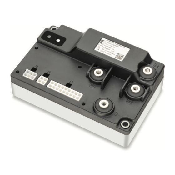
Model 1226
Brushed Permanent Magnet Controller
Read Instructions Carefully!
Specifications are subject to change without notice.
© 2019 Curtis Instruments, Inc. ® Curtis is a registered trademark of Curtis Instruments, Inc.
© The design and appearance of the products depicted herein are the copyright of Curtis Instruments, Inc.
Curtis Instruments, Inc.
200 Kisco Avenue
Mt. Kisco, NY 10549
www.curtisinstruments.com
53229, RevA 9/19
Advertisement
Table of Contents
Troubleshooting

Related Manuals for Curtis 1226


Summary of Contents for Curtis 1226
- Page 1 Specifications are subject to change without notice. © 2019 Curtis Instruments, Inc. ® Curtis is a registered trademark of Curtis Instruments, Inc. © The design and appearance of the products depicted herein are the copyright of Curtis Instruments, Inc. 53229, RevA 9/19...
-
Page 2: Table Of Contents
Throttle Pot ........................... 15 Speed Limit Pot ........................17 Keyswitch ..........................17 Emergency Stop Switch......................18 Interlock Input ........................18 Push Switch .......................... 18 Emergency Reverse Input ...................... 19 Belly Button Check ........................ 20 pg. ii Curtis Model 1226 – September 2019... - Page 3 Understanding the HPD/SRO Function ................... 36 Interlock Braking Menu ......................36 Main Relay Menu ........................37 EM Brake Menu ........................38 Understanding Electromagnetic Braking ................38 Battery Menu ........................39 Overvoltage and Undervoltage Protection ................39 Curtis Model 1226 – September 2019 pg. iii...
- Page 4 INPUTS MENU ..........................60 Switches Menu ........................60 Analog Inputs Menu ......................61 Control Inputs Menu ......................61 5: INITIAL SETUP ..........................62 Configure the Wiper Voltage ....................63 Confirm Throttle Operation ....................64 pg. iv Curtis Model 1226 – September 2019...
- Page 5 APPENDIX A: VEHICLE DESIGN CONSIDERATIONS REGARDING ELECTROMAGNETIC COMPATIBILITY (EMC) ................... 86 EMISSIONS ..........................86 IMMUNITY ........................... 86 APPENDIX B: EN 13849 COMPLIANCE, CURTIS 1226 CONTROLLER ............ 88 APPENDIX C: CURTIS PROGRAMMING DEVICES .................. 90 PC PROGRAMMING STATION (1314) ..................... 90 HANDHELD PROGRAMMER (1313) ....................90 PROGRAMMER FUNCTIONS ......................
- Page 6 FIGURE 12: THROTTLE RESPONSE PARAMETERS ................35 FIGURE 13: DIAGNOSTICS MENU FAULTS ..................74 FIGURE 14: FAULT CODE LEDs ......................75 FIGURE 15: SAFETY CHANNEL BLOCK DIAGRAM, CURTIS 1226 CONTROLLER ........88 pg. vi Curtis Model 1226 – September 2019...
- Page 7 TABLE 22: SINGLE AND DUAL SWITCH THROTTLE CONNECTIONS ............25 TABLE 23: SPEED SENSOR SPECIFICATIONS ..................25 TABLE 24: MOTOR TEMPERATURE SENSOR SPECIFICATIONS ............. 26 TABLE 25: THROTTLE TYPES AND DRIVING DIRECTION ..............34 Curtis Model 1226 – September 2019 pg. vii...
- Page 8 TABLE OF CONTENTS cont’d TABLE 26: HPD AND SRO ........................36 TABLE 27: 1226 CONTROLLER VOLTAGE LIMITS ................. 39 TABLE 28: AUX 1 TYPE AND AUX 2 TYPE PARAMETER VALUES ............46 TABLE 29: SUPERVISION ERROR FIELD VALUES ................. 57 TABLE 30: IR COMP AND ANTI-ROLLBACK COMP GUIDELINES ............
-
Page 9: 1: Overview
The Curtis Model 1226 motor speed controller provides efficient, optimal control of permanent magnet drive motors for battery powered vehicles. The 1226 controller is optimized for use on light duty Class III pallet trucks and sweeper scrubber floorcare machines. Highly flexible programmability allows the controller to be used on any low power permanent magnet motor application. -
Page 10: Easy Installation And Set-Up
• Easily programmed with the Model 1313 handheld programmer or 1314 PC programming station, or can be supplied pre-programmed. • Compatible with industrial tiller handle wigwag throttles such as the Curtis Model ET-190E. • Simplified troubleshooting and diagnostics. • Industry standard Molex Mini-fit Jr. logic connectors and heavier duty M5 threaded busbars for battery and motor wiring. -
Page 11: Valuable Additional Features
GETTING THE MOST OUT OF YOUR CONTROLLER Read and apply the information in this manual. While you need to be familiar with the entire manual, the following chapters are particularly critical to the proper operation of the 1226 controller: •... -
Page 12: 2: Installation And Wiring
This chapter explains how to mount and wire the controller. MOUNTING THE CONTROLLER The 1226 controller can be oriented in any position, but the location should be carefully chosen to keep the controller clean and dry. If you cannot find a clean, dry mounting location you must use a cover to shield the controller from CAUTION water and contaminants. -
Page 13: High Current Connections
Curtis Model 1226 – September 2019 Return to TOC You must heed the following warnings: Working on electrical systems is potentially dangerous. Protect yourself against uncontrolled operation, high current arcs, and outgassing from lead-acid batteries: UNCONTROLLED OPERATION—Some conditions could cause the motor to run out of control. -
Page 14: Low Current Connections
Curtis Model 1226 – September 2019 Return to TOC LOW CURRENT CONNECTIONS The low current connections are provided by 3 connectors, which are listed in Table 2. Table 2 Low Current Connectors Connector Description Motor connector Communication port Logic connector The connectors’... -
Page 15: Communication Port (J2)
Curtis Model 1226 – September 2019 Return to TOC Communication Port (J2) The 4-pin communication connector handles serial communications and the external +14V power supply. Use a Molex #39-28-8040, mating connector: Molex #39-01-2045 with appropriate 45750 series crimp terminals. Figure 4 Communication Connector Pins (J2) Table 4 describes the connector’s pins. -
Page 16: Table 5 J3 Connector
Curtis Model 1226 – September 2019 Return to TOC Table 5 J3 Connector Pin Number Typical Function Switch Input Analog Input LED Driver J3-1 Keyswitch input J3-2 Horn driver J3-3 Interlock input J3-4 Emergency reverse NC input J3-5 BDI output... -
Page 17: Pin Protection
Curtis Model 1226 – September 2019 Return to TOC Pin Protection Table 6 describes the specifications for pin protection. Table 6 Pin Protection Specifications Specification Pins Model Value Referenced Pins Maximum Forward All pins other than the I/O 1226-2201 +36 VDC... -
Page 18: Wiring Diagram: Standard Configuration
Return to TOC WIRING DIAGRAM: STANDARD CONFIGURATION Figure 6 is a representative wiring diagram for the Curtis 1226 models. The diagram is for a Class III vehicle that has the operator controls directly wired to the controller. Note: The wiring diagram is designed for typical Class III vehicles and may not fully meet your application’s requirements. -
Page 19: Inputs And Outputs (I/Os)
Return to TOC INPUTS AND OUTPUTS (I/Os) Unlike many controllers that have preconfigured I/Os and fixed functions, the 1226 controller has flexible I/Os that can be used with any low power permanent magnet motor application. The controller provides a set of predefined functions that are typically assigned to the I/Os. When your application requires one of these functions, you’ll use a parameter to assign the function to its... -
Page 20: Switch Inputs
Curtis Model 1226 – September 2019 Return to TOC The following considerations apply to the voltage range specifications: • To provide a sufficient response rate while also allowing for effective filtering, the controller reads the inputs’ signals at least every 1ms. -
Page 21: Switches With Integrated Led Drivers
Curtis Model 1226 – September 2019 Return to TOC You can assign the switch inputs to functions other than their typically used functions. Use the Switch Assignment menu to assign switches; see page Table 10 describes the specifications for switch inputs. Some values are model-dependent. -
Page 22: Driver Outputs
Return to TOC Driver Outputs The 1226 controller supports output through 3 generic drivers. Drivers 1 and 3 are low side drivers that provide PWM. Driver 2 can be configured as either a low side driver with PWM or a high side driver without PWM. -
Page 23: Throttle Pot
Curtis Model 1226 – September 2019 Return to TOC Table 13 describes the generic driver specifications. Table 13 Generic Driver Specifications Specification Value Active level The active level depends upon the driver: • Drivers 1 and 3: Low side driver •... -
Page 24: Figure 7: Wiring A 2-Wire Throttle Pot
Curtis Model 1226 – September 2019 Return to TOC Use the Analog 1 Type parameter value to specify the vehicle’s pot type. See page Figure 7 and Figure 8 show how to wire 2-wire and 3-wire throttle pots. J3-13 I/O GND... -
Page 25: Speed Limit Pot
Curtis Model 1226 – September 2019 Return to TOC Speed Limit Pot A speed limit pot allows the operator to adjust the vehicle speed. A 100kΩ pot is recommended. If you are using a speed limit pot, perform the following steps. -
Page 26: Emergency Stop Switch
Figure Interlock Input To ensure operator safety, the 1226 controller does not allow vehicles to start from rest on level ground until the operator specifies the driving direction and applies throttle. The interlock input indicates whether the operator intends to power up and drive the system, as described below: •... -
Page 27: Emergency Reverse Input
Curtis Model 1226 – September 2019 Return to TOC Emergency Reverse Input Emergency reverse is typically used in Class III material handling vehicles. When emergency reverse is activated, the controller produces a rapid braking force to quickly stop the vehicle, then drives the vehicle in the opposite direction. -
Page 28: Belly Button Check
Curtis Model 1226 – September 2019 Return to TOC Belly Button Check You can use the Generic Driver 2 output (pin J3-12) to perform a belly button check (BB check). The belly button check tests whether the emergency reverse wiring is broken. If the controller detects the wiring is broken, the controller generates a BB Wiring Fault. -
Page 29: Electromagnetic Braking
EM Brake menu to configure the holding voltage and other electromagnetic braking parameters; page Mode Switch Your vehicle can include a mode switch that allows operators to choose from the 1226 controller’s speed modes. One mode can be configured for faster outdoor driving and the other for slower indoor driving. -
Page 30: Battery Discharge Indicator (Bdi)
Return to TOC Battery Discharge Indicator (BDI) The 1226 controller can drive a 0V-5V BDI panel meter that displays the battery’s state-of-charge. The battery must be put through a full charge cycle with the controller installed before the BDI will begin operation. -
Page 31: External Status Led
Alternatively, an LED with a built-in resistor can be used; it should be rated for the battery’s nominal voltage operation. Horn The 1226 controller has a dedicated horn driver that drives with either the low side or high side method. The driver’s maximum current is 30mA. To use a horn driver, do the following: •... -
Page 32: External Power Supply
Curtis Model 1226 – September 2019 Return to TOC External Power Supply The controller provides two output pins for external power supply, as described in Table Table 20 External Power Supply Pins External Power Supply Voltage J1-1 +14V J2-4 Table 21 describes the specifications for the external power supply outputs. -
Page 33: Reverse Switch
Speed Sensor The 1226 controller provides an input for a single wire motor speed sensor. If the vehicle uses a speed sensor, you can configure the controller to strictly limit vehicle speed. -
Page 34: Motor Temperature Sensor
Return to TOC Motor Temperature Sensor The 1226 controller provides an input for a motor temperature sensor and can apply a limited operating strategy (LOS) to prevent damage caused by overheating. The input measures the sensor’s resistance, then uses the measured resistance to calculate the temperature. -
Page 35: 3: Programmable Parameters
Curtis Model 1226 – September 2019 Return to TOC 3 — PROGRAMMABLE PARAMETERS The 1226 controller has numerous parameters that you can program using a Curtis handheld programmer or Curtis PC Programming Station. Use these parameters to customize a vehicle’s performance and functionality. -
Page 36: Mode 1 And Mode 2 Menus
Curtis Model 1226 – September 2019 Return to TOC Mode 1 and Mode 2 Menus Use the Mode 1 and Mode 2 menus to configure the speed modes. The following table describes the Mode 1 and Mode 2 menus’ parameters. -
Page 37: Other Menu
Curtis Model 1226 – September 2019 Return to TOC SPEED MODE MENU — MODE 1 AND MODE 2 MENUS, cont’d PARAMETER VALUES DEFAULT DESCRIPTION Rev Neutral Decel Rate HS 0.1s-8.0s 3.0s Sets the rate, in seconds, at which the vehicle decelerates when the throttle is released to neutral while the vehicle is moving in reverse at high speed. -
Page 38: Fine Tuning Menu
Curtis Model 1226 – September 2019 Return to TOC Fine Tuning Menu Use the Fine Tuning menu’s parameters to define the high and low speed thresholds for all parameters with names ending in HS and LS. For examples, see the following topics:... -
Page 39: Understanding Low And High Speed Acceleration Rates
Curtis Model 1226 – September 2019 Return to TOC Understanding Low and High Speed Acceleration Rates You can optimize a vehicle’s throttle response by configuring acceleration rates for low and high speeds. These rates are defined with the Full Accel Rate LS and Full Accel Rate HS parameters. You can configure different acceleration rates for each speed mode. -
Page 40: Understanding Low And High Speed Brake Deceleration Rates
Curtis Model 1226 – September 2019 Return to TOC Understanding Low and High Speed Brake Deceleration Rates You can optimize the rates at which a vehicle decelerates when full throttle is applied in the opposite direction. These deceleration rates are configured with the Full Brake Rate HS and Full Brake Rate LS parameters. -
Page 41: Throttle Menu
Curtis Model 1226 – September 2019 Return to TOC Throttle Menu Use the Throttle menu to specify the type of throttle used by the vehicle, configure the throttle’s responsiveness, and configure the HPD/SRO function. Note: The Forward and Reverse Deadband, Max, Offset, and Map parameter values are percentages of the throttle’s maximum output voltage or resistance. -
Page 42: Table 25 Throttle Types And Driving Direction
Curtis Model 1226 – September 2019 Return to TOC THROTTLE MENU, cont’d PARAMETER VALUES DEFAULT DESCRIPTION HPD/SRO Type [PCF] Indicates whether the HPD/SRO function is enabled. If HPD/SRO is enabled, the controller generates the HPD/ Sequencing fault when it detects an HPD condition. Whether the... -
Page 43: Understanding The Throttle Response Parameters
Curtis Model 1226 – September 2019 Return to TOC Understanding the Throttle Response Parameters The Forward and Reverse Deadband, Max, and Map parameters set the controller output that is generated at various throttle wiper voltages. The Forward and Reverse Offset parameters define the output generated by the controller when the throttle is first rotated out of the neutral deadband. -
Page 44: Understanding The Hpd/Sro Function
Curtis Model 1226 – September 2019 Return to TOC Understanding the HPD/SRO Function The HPD/SRO safety function protects users from unexpected starts when the interlock input changes from off to on. If the HPD/SRO parameter is enabled and one of the conditions described in Table 26 occurs, the controller generates an HPD/Sequencing Fault. -
Page 45: Main Relay Menu
Curtis Model 1226 – September 2019 Return to TOC Main Relay(Contactor) Menu The Main Relay(Contactor) parameters apply to the main contactor in models that use a main contactor. For other models, the parameters apply to the internal relay. The following table describe the Main Relay(Contactor) parameters. -
Page 46: Em Brake Menu
Curtis Model 1226 – September 2019 Return to TOC EM Brake Menu Use the EM Brake menu to configure electromagnetic braking (EM). The following table describes the menu’s parameters. Note: For information on the electromagnetic braking feature, see page EM BRAKE MENU... -
Page 47: Battery Menu
(36V/48V model only) Overvoltage and Undervoltage Protection The 1226 controller’s overvoltage protection cuts back regen current to prevent damage to batteries and other electrical system components. The controller’s undervoltage protection prevents systems from operating at voltages below minimum voltage requirements. -
Page 48: Undervoltage Controller Menu
Curtis Model 1226 – September 2019 Return to TOC Undervoltage Controller Menu The Undervoltage Controller parameters allow you to configure how the controller handles undervoltage conditions. Note: To configure these parameters, you must be familiar with the controller’s system voltage ranges. -
Page 49: Bdi Setup Menu
Curtis Model 1226 – September 2019 Return to TOC BDI Setup Menu The BDI Setup parameters allow you to configure the Battery Discharge Indicator (BDI) output for the system’s battery, charger, and expected drive cycle. The following list defines terms used in the parameter descriptions: •... -
Page 50: Emergency Reverse Menu
Curtis Model 1226 – September 2019 Return to TOC BATTERY MENU — BDI SETUP MENU, cont’d PARAMETER VALUES DEFAULT DESCRIPTION BDI Reset Percent 0%-100% Sets the percentage of battery voltage above which the BDI percentage will not reset when the keyswitch is turned on. - Page 51 Curtis Model 1226 – September 2019 Return to TOC EMERGENCY REVERSE MENU PARAMETER VALUES DEFAULT DESCRIPTION EMR Input Type [PCF] Sets whether emergency reverse is activated from the normally open (NO) switch, normally closed (NC) switch, or a complementary usage of both NO and NC switches:...
-
Page 52: Horn Menu
Curtis Model 1226 – September 2019 Return to TOC Horn Menu The following table describes the parameters on the Horn menu. HORN MENU PARAMETER VALUES DEFAULT DESCRIPTION Type [PCF] Specifies the horn driver type, if any: 0 = Disable the horn... -
Page 53: Load Hold Contactor Driver Menu
Curtis Model 1226 – September 2019 Return to TOC Load Hold Contactor Driver Menu The following table describes the parameters on the Load Hold Contactor Driver menu. DRIVERS MENU — LOAD HOLD CONTACTOR DRIVER MENU PARAMETER VALUES DEFAULT DESCRIPTION Load Hold Contactor Pull In... -
Page 54: Misc Menu
Curtis Model 1226 – September 2019 Return to TOC The following table describes the values you can specify for the Aux 1 Type and Aux 2 Type parameters. Table 28 Aux 1 Type and Aux 2 Type Parameter Values Value... -
Page 55: Controller Setup Menu
Curtis Model 1226 – September 2019 Return to TOC Controller Setup Menu The Controller Setup menu contains the following menus: CONTROLLER SETUP MENU ANALOG INPUTS MENU...... p. 47 IO ASSIGNMENT MENU...... p. 49 OUTPUTS MENU....... p. 51 CURRENT LIMITS MENU..... - Page 56 Curtis Model 1226 – September 2019 Return to TOC Analog 2, 3, 4, and 5 Menus The following table describes the parameters on the Analog 2, Analog 3, Analog 4, and Analog 5 menus. CONTROLLER SETUP MENU — ANALOG INPUTS MENU — ANALOG 2, 3, 4, AND 5 MENUS...
-
Page 57: Io Assignment Menu
Curtis Model 1226 – September 2019 Return to TOC IO Assignment Menu The IO Assignment menu contains the following menus: • Controls Menu • Switch Assignment Menu (page 49) • Coil Drivers Menu (page 50) • Misc Menu (page 50) Controls Menu Use the Controls parameters to specify the analog inputs for the throttle and speed limit pot. - Page 58 Curtis Model 1226 – September 2019 Return to TOC Coil Drivers Menu The following table describes the parameters on the Coil Drivers menu. CONTROLLER SETUP MENU — IO ASSIGNMENT MENU — COIL DRIVERS MENU PARAMETER VALUES DEFAULT DESCRIPTION Main Contactor Driver (1226-...
-
Page 59: Outputs Menu
Curtis Model 1226 – September 2019 Return to TOC Outputs Menu The Outputs menu contains the Driver 1, Driver 2, and Driver 3 menus. Driver 1, Driver 2, and Driver 3 Menus The following table describes the parameters on the Driver 1, Driver 2, and Driver 3 menus. -
Page 60: Motor Setup Menu
Curtis Model 1226 – September 2019 Return to TOC Motor Setup Menu The Motor Setup menu contains the following menus: MOTOR SETUP MENU MOTOR MENU..........p. 52 COMPENSATION MENU......p. 53 SPEED SENSOR MENU......... p. 53 MOTOR TEMPERATURE CONTROL MENU.. -
Page 61: Compensation Menu
Curtis Model 1226 – September 2019 Return to TOC Compensation Menu Use the Compensation parameters to configure the motor resistance that the controller applies to compensate for the following conditions: • Increased load caused by uneven terrain. • The operator releases the throttle to neutral at near-zero speeds while the vehicle is on a slope. -
Page 62: Motor Temperature Control Menu
Curtis Model 1226 – September 2019 Return to TOC MOTOR SETUP MENU — SPEED SENSOR MENU, cont’d PARAMETER VALUES DEFAULT DESCRIPTION 0-100% Specifies how aggressively the controller attempts to limit the motor speed to the Max Speed. Larger values provide a slower response time. - Page 63 Curtis Model 1226 – September 2019 Return to TOC MOTOR SETUP MENU — MOTOR TEMPERATURE CONTROL MENU, cont’d PARAMETER VALUES DEFAULT DESCRIPTION Braking Thermal Cutback On/Off Sets whether the controller cuts back regen braking current if the Enable motor reaches the Temperature Hot threshold:...
-
Page 64: 4: Monitor Menu
Return to TOC 4 — MONITOR MENU The Monitor menu lets you use Curtis programming devices to observe real-time data for the vehicle. You can use this data when you are configuring programmable parameters and troubleshooting the system. For information on programming devices, see... -
Page 65: Table 29: Supervision Error Field Values
Curtis Model 1226 – September 2019 Return to TOC MONITOR MENU — CONTROLLER MENU, cont’d FIELD VALUES DESCRIPTION Charge Inhibit On/Off Indicates whether the charge inhibit function is active. Lift Lockout On/Off Indicates whether the hydraulic lift lockout function is active. -
Page 66: Battery Menu
Curtis Model 1226 – September 2019 Return to TOC BATTERY MENU The following table describes the fields on the Battery menu. MONITOR MENU — BATTERY MENU FIELD VALUES DESCRIPTION 0-100% Indicates the battery's state of charge For more information, see... -
Page 67: Motor Menu
Curtis Model 1226 – September 2019 Return to TOC MOTOR MENU The following table describes the fields on the Motor menu. MONITOR MENU — MOTOR MENU FIELD VALUES DESCRIPTION Motor Temperature –40 – 250°C Indicates the temperature read by the temperature sensor. -
Page 68: Inputs Menu
Curtis Model 1226 – September 2019 Return to TOC INPUTS MENU The Inputs menu contains the following menus: • Switches Menu • Analog Inputs Menu (page 61) • Control Inputs Menu (page 61) Switches Menu The following table describes the fields on the Switches menu. -
Page 69: Analog Inputs Menu
Curtis Model 1226 – September 2019 Return to TOC Analog Inputs Menu The following table describes the fields on the Analog Inputs menu. MONITOR MENU — INPUTS MENU — ANALOG INPUTS MENU FIELD VALUES DESCRIPTION Throttle Pot Percent 0-100% Indicates the amount of throttle voltage or resistance as a percentage of full throttle. -
Page 70: 5: Initial Setup
Curtis Model 1226 – September 2019 Return to TOC 5 — INITIAL SETUP To configure the 1226 controller so that it is compatible with your vehicle’s characteristics and requirements, perform the following procedures: Step 1. Prepare the Vehicle. Step 2. Configure the Throttle. (page 62) Step 3. -
Page 71: Configure The Wiper Voltage
Curtis Model 1226 – September 2019 Return to TOC Configure the Deadband Check whether the throttle’s deadband range provides a good balance. The deadband should be wide enough for the throttle to return to neutral when released, but also should not allow an excessive amount of travel in the neutral zone. -
Page 72: Confirm Throttle Operation
Curtis Model 1226 – September 2019 Return to TOC Confirm Throttle Operation To confirm the throttle is operating correctly, select a direction and operate the throttle. The motor should begin to rotate in the selected direction. If it does not, verify the wiring to the throttle and motor. - Page 73 Curtis Model 1226 – September 2019 Return to TOC Note: You’ll monitor the Motor Resistance Measured field in the following steps. 8. With the speed limit pot set at maximum, apply the throttle full forward, driving the vehicle against the immovable object.
-
Page 74: 6: Tuning Vehicle Performance
Return to TOC 6 — TUNING VEHICLE PERFORMANCE You can customize many aspects of vehicle performance by adjusting the 1226 controller’s programmable parameters. Once you have tuned a vehicle system, you can make the parameter values standard for that system or vehicle model. - Page 75 Curtis Model 1226 – September 2019 Return to TOC 4. Select Program » Application Setup » Speed Mode, then perform the flowing steps for each speed mode. a. Select Mode 1 or Mode 2. b. Set the Full Accel Rate LS parameter to the rate at which the vehicle should accelerate when full throttle is applied while the vehicle is traveling at low speed.
-
Page 76: Table 30: Ir Comp And Anti-Rollback Comp Guidelines
Curtis Model 1226 – September 2019 Return to TOC Step 4: Adjust IR Compensation Use the IR Comp and Anti-Rollback Comp parameters to configure the motor resistance that the controller applies to compensate for the following conditions: • Increased load caused by uneven terrain. (IR Comp) •... - Page 77 Curtis Model 1226 – September 2019 Return to TOC Step 5: Fine-tune the Vehicle’s Response Smoothness You can soften and smooth vehicle response by configuring the Gear Soften and Soft Start parameters: • Gear Soften defines how the vehicle decelerates when the throttle is released to neutral and accelerates when the throttle is reapplied.
- Page 78 Curtis Model 1226 – September 2019 Return to TOC Some users prefer a softened feel, while others set Gear Soften to 0% because they prefer a linear vehicle response. When you set this parameter, take into consideration that softened slack take-up is easier on the transaxle gears and may extend the transaxle operating life.
-
Page 79: 7: Calibrating The Battery Discharge Indicator (Bdi) Output
Curtis Model 1226 – September 2019 Return to TOC 7 — CALIBRATING THE BATTERY DISCHARGE INDICATOR (BDI) OUTPUT If your vehicle system includes a Battery Discharge Indicator (BDI) gauge, you must calibrate the controller for the battery’s size, the charger’s type and size, and the expected driving conditions. - Page 80 Curtis Model 1226 – September 2019 Return to TOC Step 2: Set Full Charge Voltage Set the Full Charge Voltage parameter by taking the following steps: 1. Plug in the charger. 2. Fully charge the batteries. 3. With the charger still attached and running, measure the battery voltage with a voltmeter.
- Page 81 The typical method is to require a full recharge, which means the BDI percentage is reset only after the battery is fully charged. However, the 1226 controller can be configured to allow the operator to stop charging in mid-cycle and then view a partial charge reading.
-
Page 82: 8: Diagnostic And Troubleshooting
Curtis Model 1226 – September 2019 Return to TOC 8 — DIAGNOSTIC AND TROUBLESHOOTING The 1226 controller provides diagnostic information to help technicians troubleshoot drive system problems. You can view the diagnostic information using Curtis programming devices and the controller’s status LEDs. -
Page 83: Led Diagnostics
Curtis Model 1226 – September 2019 Return to TOC LED DIAGNOSTICS The 1226 controller has red and yellow status LEDs. Table 32 describes how the LEDs indicate the controller’s status. Table 32 LED Statuses Status Red Light Yellow Light The flash cycle is 1.5s. The LED blinks for 500ms, followed by a 1s delay. -
Page 84: External Status Led
Curtis Model 1226 – September 2019 Return to TOC External Status LED One of the controller’s LED drivers can be used to display fault codes with an LED in the operator’s control panel. During normal operation the status LED is steadily on. -
Page 85: Table 33: Faults
Curtis Model 1226 – September 2019 Return to TOC Table 33 Faults Code Fault and Fault Action Possible Causes Set and Clear Conditions Controller Overcurrent • External short of phase M1 or M2 motor Set: The phase current exceeds the connections. - Page 86 Curtis Model 1226 – September 2019 Return to TOC Table 33 Faults, cont’d Code Fault and Fault Action Possible Causes Set and Clear Conditions Set: The capacitor bank voltage Undervoltage Cutback • The batteries need recharging. dropped below the Undervoltage •...
- Page 87 Curtis Model 1226 – September 2019 Return to TOC Table 33 Faults, cont’d Code Fault and Fault Action Possible Causes Set and Clear Conditions Set: The Main Contactor driver is • The main driver is open or shorted. Main Driver either open or shorted.
- Page 88 Curtis Model 1226 – September 2019 Return to TOC Table 33 Faults, cont’d Code Fault and Fault Action Possible Causes Set and Clear Conditions Set: The capacitor bank voltage Main Contactor Did Not Close • The main contactor tips are oxidized, burnt, or not making good contact.
- Page 89 Curtis Model 1226 – September 2019 Return to TOC Table 33 Faults, cont’d Code Fault and Fault Action Possible Causes Set and Clear Conditions Set: The driver is shorted or is • The driver is shorted to B–. LED Driver 1 consuming more than 30mA.
- Page 90 Curtis Model 1226 – September 2019 Return to TOC Table 33 Faults, cont’d Code Fault and Fault Action Possible Causes Set and Clear Conditions Set: Internal controller failure. Supervision The controller failed. Note: When a Supervision fault is active, the Clear: Cycle the keyswitch.
- Page 91 Curtis Model 1226 – September 2019 Return to TOC Table 33 Faults, cont’d Code Fault and Fault Action Possible Causes Set and Clear Conditions Set: The input voltage is not within Analog 1 Out of Range • The analog input’s voltage is above the voltage specified by the High parameter.
- Page 92 Curtis Model 1226 – September 2019 Return to TOC Table 33 Faults, cont’d Code Fault and Fault Action Possible Causes Set and Clear Conditions SW FAULT Defective controller. Set: The controller did not power up correctly. Clear: Cycle the keyswitch.
-
Page 93: 9: Maintenance
Return to TOC 9 — MAINTENANCE There are no user serviceable parts in the Curtis 1226 controller. Do not attempt to open, repair, or otherwise modify the controller. Doing so may damage the controller and will void the warranty. However, it is recommended that the controller’s fault history file be checked and cleared periodically, as part of routine vehicle maintenance. -
Page 94: Electromagnetic Compatibility (Emc)
(created by long wires spaced far apart). Contactor drivers and the motor drive output from Curtis controllers can contribute to RF emissions. Both types of output are pulse width modulated square waves with fast rise and fall times that are rich in harmonics. (Note: contactor drivers that are not modulated will not contribute to emissions.) The impact of these switching waveforms can... - Page 95 Curtis Model 1226 – September 2019 Return to TOC the controller in a metal box. Some Curtis controllers are enclosed by a heatsink that also provides shielding around the controller circuitry, while others are partially shielded or unshielded. In some applications, the vehicle designer will need to mount the controller within a shielded box on the end product.
-
Page 96: Appendix B: En 13849 Compliance, Curtis 1226 Controller
To mitigate the hazards typically found in machine operations, EN13849 requires that safety functions be defined; these must include all the input, logic, outputs, and power circuits that are involved in any potentially hazardous operation. Two safety functions are defined for Curtis 1226 controllers: Uncommanded Powered Motion and Motor Braking Torque. -
Page 97: Table 34: Safety Performance
Curtis Model 1226 – September 2019 Return to TOC Curtis has analyzed each safety function and calculated its Mean Time To Dangerous Failure (MTTFd) and Diagnostic Coverage (DC), and designed them against Common Cause Faults (CCF). The safety-related performance of the Curtis 1226 is summarized in Table 34:... -
Page 98: Appendix C: Curtis Programming Devices
Return to TOC APPENDIX C — CURTIS PROGRAMMING DEVICES Curtis programmers provide programming, diagnostic, and test capabilities for Curtis controllers. The power for operating the programmer is supplied by the host controller via a 4-pin connector. When the programmer powers up, it gathers information from the controller. -
Page 99: Appendix D: Specifications
Curtis Model 1226 – September 2019 Return to TOC APPENDIX D — SPECIFICATIONS Voltage Ranges Nominal Battery Severe Severe Voltage Brownout Undervoltage Undervoltage Overvoltage Overvoltage 9.6V 14.4V 36/48V 14.4V PWM operating frequency 14.7 kHz Electrical isolation to heatsink 500 VAC (minimum) Package environmental rating Electronics sealed to IP54 per IEC 60529.
Need help?
Do you have a question about the 1226 and is the answer not in the manual?
Questions and answers