Table of Contents
Advertisement
CURTIS PMC
235 East Airway Boulevard
Livermore, California 94568 USA
Tel: 925-961-1088
Fax: 925-961-1099
www.curtisinst.com
MANUAL
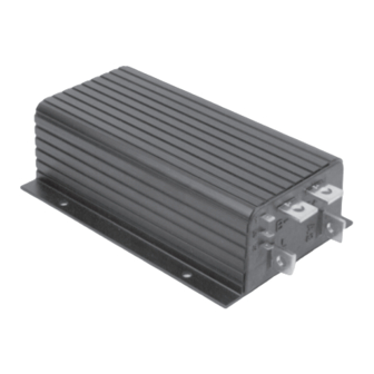
1204/5
MOTOR CONTROLLERS
© 1999 CURTIS INSTRUMENTS, INC.
DESIGN OF CURTIS 1200 SERIES
CONTROLLERS PROTECTED BY U.S.
PATENT NO. 4626750.
1204 / 1205 Manual
p/n 98690, Rev. B: May 1999
Advertisement
Table of Contents
Troubleshooting


Need help?
Do you have a question about the 1204 and is the answer not in the manual?
Questions and answers