Table of Contents
Advertisement
Manual
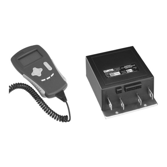
Model 1207B
MultiMode™ Electronic Motor Controller
Read Instructions Carefully!
Specifications are subject to change without notice.
© 2012 Curtis Instruments, Inc. ® Curtis is a registered trademark of Curtis Instruments, Inc.
© The design and appearance of the products depicted herein are the copyright of Curtis Instruments, Inc.
Curtis Instruments, Inc.
200 Kisco Avenue
Mt. Kisco, NY 10549
www.curtisinstruments.com
53118 Rev A 6/12
Advertisement
Table of Contents
Troubleshooting

Related Manuals for Curtis MultiMode 1207B


Summary of Contents for Curtis MultiMode 1207B
- Page 1 Specifications are subject to change without notice. © 2012 Curtis Instruments, Inc. ® Curtis is a registered trademark of Curtis Instruments, Inc. © The design and appearance of the products depicted herein are the copyright of Curtis Instruments, Inc. 53118 Rev A 6/12...
-
Page 3: Table Of Contents
Testing the Fault Detection Circuitry.........19 5. DIAGNOSTICS AND TROUBLESHOOTING....20 LED Diagnostics..............20 Programmer Diagnostics ............21 6. HANDHELD PROGRAMMER ..........23 Programmer Operation .............24 Progammer Menus.............26 Program Menu ............26 Monitor Menu ............27 Fault Menu..............27 Glossary of Features and Functions APPENDIX A Specifications APPENDIX B Curtis 1207B Manual... - Page 4 8: Wiring for 3-wire pot throttle ........12 fig. 9: Wiring for Curtis ET-XXX electronic throttle ..12 fig. 10: Wiring for 0–5kΩ throttle ........13 fig. 11: Alternative wiring for emergency reverse check ..13 fig. A-1: Ramp shape, with max speed = 100% and creep speed = 0% ...........
-
Page 5: Overview
MOSFET power section gives the 1207B controller high power and advanced features in a simple, compact package. The optional programmers (Curtis 1311 and 1314) enable the user to set parameters, conduct tests, and obtain diagnostic information quickly and easily. - Page 6 ✓ Solid, well-protected construction—with an aluminum mounting plate and injection-molded cover. Familiarity with your Curtis controller will help you install and operate it prop- erly. We encourage you to read this manual carefully. If you have questions, please contact the Curtis office nearest you.
-
Page 7: Installation And Wiring
Although not usually necessary, a thermal joint compound can be used to improve heat conduction from the case to the mounting surface. Fig. 2 Mounting 165 (6.50) dimensions, Curtis 1207B controller. 127 (5.00) 22 (0.85) 28 (1.1) Status LED (4.80) 66 (2.6) -
Page 8: Connections: Low Current
Pin 9 emergency reverse (BB) check output [optional] Pin 10 reverse input Pin 11 forward input Pin 12 emergency reverse input Pin 13 mode selection input Pin 14 brake input Pin 15 keyswitch input (KSI) Pin 16 Curtis 1207B Manual... -
Page 9: Connections: High Current
Cables are fastened to the bus bars by M8 ( ⁄ ") bolts. When tightening the bolts, two opposing wrenches should be used to prevent bending the bus bars and putting undue strain on the internal connections. Curtis 1207B Manual... -
Page 10: Wiring: Standard Configuration (Series Motor)
The configuration shown in Figure 3 is a typical arrangement for a series mo- tor. Curtis controllers are designed for use in a wide range of applications, and accordingly can be installed in a variety of ways to best meet customer needs. - Page 11 REVERSE REVERSE FORWARD CONTACTOR MAIN 2-WIRE POT REVERSE (5 kΩ) CONTACTOR CONTACTOR The throttle shown in Figure 3 is a 5kΩ–0 type. Various other throttles can also be accommodated, and are discussed in the throttle wiring section. Curtis 1207B Manual...
-
Page 12: Wiring: Compound Motor Configuration
In this controller, the MOSFET output driver is used to drive the shunt field. The wiring for a compound wound motor with armature reversing is shown in Figure 4. Fig. 4 Compound SWITCHES motor wiring diagram, CONTACTORS MULTI EMERGENCY Curtis 1207B controller. BRAKE MODE REVERSE REVERSE SHUNT MAIN FORWARD THROTTLE 5kΩ–0 (TYPICAL) - Page 13 The throttle shown in Figure 4 is a 5kΩ–0 type. Various other throttles can also be accommodated, and are discussed in the throttle wiring section. Polarity protection diodes and control fuses must be sized appropriately to handle the increased current from the shunt field. Curtis 1207B Manual...
-
Page 14: Wiring: Throttle
If the throttle you are planning to use is not covered, please contact the Curtis office nearest you. 5kΩ–0 Throttle (“Type 1”) The 5kΩ–0 throttle (called a “Type 1” throttle in the programming menu of the handheld programmer) is a 2-wire resistive throttle that connects between the 5kΩ–0/0–5kΩ... -
Page 15: 0-5V, 3-Wire Potentiometer, And Electronic Throttles ("Type 2")
PIN KEY Pin 7 Pot Low Pin 6 0–5V Input SENSOR GROUND Ground-referenced 0–5V throttle (Shunt impedance 150 k Ω to ground) PIN KEY Pot Low Pin 7 0–5V Input Pin 6 4.7 kΩ Pot High Pin 5 Curtis 1207B Manual... -
Page 16: Fig. 8: Wiring For 3-Wire Pot Throttle
0–5V Input Pin 6 Pot High Pin 5 Curtis ET-XXX Electronic Throttle The Curtis ET-XXX provides throttle and forward/reverse inputs to the 1207B controller. Wiring for the Curtis ET-XXX is shown in Figure 9. Fig. 9 Wiring for Curtis ET-XXX electronic throttle (“Type 2”). -
Page 17: 0-5Kω Throttle ("Type 3")
This feature must be enabled at Curtis. If the option is selected and the check wire is not connected, the vehicle will not operate. If the option is not selected and the check wire is connected, no harm will occur—but continuity... -
Page 18: Switches And Other Hardware
Albright SW80 or SW180. After initial closing of the contacts, inrush currents flow as the controller’s internal filter capacitors are charged. A 250Ω, 5W resistor (such as Curtis p/n MP-2) can be used across the contactor to precharge the capacitors and reduce the inrush current through the contacts. -
Page 19: Installation Checkout
If it does not, verify the wiring to the forward/reverse switches, forward/reverse contactors, and motor. The motor should run proportionally faster with increasing throttle. If not, refer to Section 5. Curtis 1207B Manual... - Page 20 10. Check to see whether the emergency reverse (belly button) feature is working correctly. If you have the optional emergency reverse check wir- ing, verify that the circuit is operational by momentarily disconnecting one of the emergency reverse wires. The vehicle should be disabled and a fault indicated. Curtis 1207B Manual...
-
Page 21: Adjustment Of Parameters
* Instructions for using the 1314 PC Programming Station are included in that programmer’s software. In this 1207B controller manual, only the 1311 handheld programmer is described. However, the 1314 has all the capabilities and features of the 1311. Curtis 1207B Manual... -
Page 22: Maintenance
4 — MAINTENANCE MAINTENANCE There are no user-serviceable parts inside the Curtis 1207B controller. No at- tempt should be made to open the controller. Opening the controller may damage it and will void the warranty. However, it is recommended that the controller exterior be cleaned peri- odically, and—if a handheld programmer is available—this periodic cleaning... -
Page 23: Testing The Fault Detection Circuitry
4. Leave the keyswitch on and remove the inline fuse wire. The vehicle status should continue to remain off. 5. Cycle the keyswitch off and on, release the brake, and apply the throttle. The vehicle should now operate normally. Curtis 1207B Manual... -
Page 24: Diagnostics And Troubleshooting
low battery voltage overvoltage thermal cutback [reserved for future use] Note: Only one fault is indicated at a time, and faults are not queued up. Curtis 1207B Manual... -
Page 25: Programmer Diagnostics
If the programmer shows the forward switch closing and the vehicle now drives normally, the problem has been corrected. Refer to the troubleshooting chart (Table 2) for suggestions covering a wide range of possible faults. Curtis 1207B Manual... -
Page 26: Table 2: Troubleshooting Chart
1. Battery voltage >33V. 2. Vehicle operating with charger attached. Th ermal C utb ac k over-/under-temp. cutback 1. Temperature >85°C or <-25°C. 2. Excessive load on vehicle. 3. Improper mounting of controller. 4. Operation in extreme environments. Curtis 1207B Manual... -
Page 27: Handheld Programmer
6 — HANDHELD PROGRAMMER HANDHELD PROGRAMMER The universal Curtis 1311 handheld programmer (optional) allows you to program, test, and diagnose Curtis programmable controllers. The program- mer is powered by the host 1207B controller, via a 4-pin Molex connector on the front panel. -
Page 28: Programmer Operation
Navigation Key will display a screen with additional information, which in this example is a bar graph. Program Creep Speed To return to the list of parameters, press the left arrow. To return to the Main Menu, press the left arrow again. Curtis 1207B Manual... - Page 29 Navigation Key to select “Fault” and then “Clear Fault History.” When asked to confirm your action, use Data Inc/Dec Key. The “+” arrow means Yes and the “-” arrow means No (that is, it cancels clearing the fault history). Curtis 1207B Manual...
-
Page 30: Progammer Menus
Type 2 = SRO on KSI plus brake input plus a direction input Type 3 = SRO on KSI plus brake input plus forward input (For more detail on these options, see Appendix A: Glossary of Features and Functions.) Curtis 1207B Manual... -
Page 31: Monitor Menu
T h e r m al Cut b ack Cutback, due to over/under temp T h rot tl e F aul t 1 Throttle input fault T h rot tl e F aul t 2 Throttle Type changed without cycling KSI Curtis 1207B Manual... -
Page 33: Appendix A Glossary Of Features And Functions
Some vehicles may have no main contactor, or the main contactor may be wired directly to the KSI or brake signal, bypassing the controller. Various protections provided for the contactor drivers ensure that the con- tactors operate correctly; see Fault detection. Curtis 1207B Manual... - Page 34 Current limiting Curtis controllers limit the motor current to a preset maximum. This feature protects the controller from damage that might result if the current were limited only by motor demand. PWM output to the power section is reduced smoothly until the motor current falls below the set limit level.
- Page 35 Fault » Fault History menu provides access to the controller’s diagnostic history file—the entire fault event list created since the diagnostic history file was last cleared. The Fault » System Faults menu, on the other hand, provides informa- tion about only the currently active faults. Curtis 1207B Manual...
- Page 36 KSI (Key Switch Input) provides power to the logic board, and initializes and starts diagnostics. In combination with the brake input, KSI enables all logic functions. Some vehicles may have no keyswitch (KSI simply tied to B+) or may have the key permanently turned on. Curtis 1207B Manual...
- Page 37 Overtemperature At overtemperature (from 85°C to 95°C), the drive current limit is linearly decreased from full set current down to zero. (Plug current, however, is not reduced—in order to provide full vehicle braking under all thermal conditions.) Curtis 1207B Manual...
- Page 38 Pulse width modulation (PWM), also called “chopping,” is a technique that switches battery voltage to the motor on and off very quickly, thereby control- ling the speed of the motor. Curtis 1200 series controllers use high frequency PWM—15 kHz—which permits silent, efficient operation.
- Page 39 Ramp shapes with the creep speed setting raised to 10% are shown in Figure A-2. Fig. A-2 Ramp shape (throttle map) for controller RAMP SHAPE MAXIMUM SPEED (100%) with maximum speed set at 100% and creep speed set at 10%. CREEP SPEED (10%) THROTTLE (percent) Curtis 1207B Manual...
- Page 40 The ramp start current limit is adjustable via the handheld programmer. The Mode 1 and Mode 2 ramp start current limits can be set independently. Curtis 1207B Manual...
-
Page 41: Appendix B Specifications
0 to 0.5 seconds, where 0 corresponds to no delay. Smooth, stepless operation Like all Curtis 1200 Series controllers, the 1207B allows superior operator control of the vehicle’s drive motor speed. The amount of current delivered to the motor is set by varying the “on” time (duty cycle) of the controller’s power MOSFET transistors. - Page 42 The maximum and minimum temperatures read at the heatsink at any time during powering of the controller are stored in the controller’s memory. These values (which can be accessed via the programmer’s Monitor menu) are cleared each time the controller’s diagnostic history file is cleared. A-10 Curtis 1207B Manual...
- Page 43 The most commonly used throttles can all be hooked up directly: 5kΩ–0 and 0–5kΩ 2-wire rheostats, 3-wire pots, 0–5V throttles, and the Curtis ET-XXX electronic throttle. Throttle full range produces 0–100% duty factor at the controller output (unless limited by other conditions).
- Page 44 If not reset, the internal timer times out and the microprocessor is “warm booted.” This causes the microprocessor to shut down its outputs (thus shutting down the controller) and attempt to restart. A-12 Curtis 1207B Manual...
- Page 45 3. Airflow at 4.8 km/h (3 mph) perpendicular to bottom of aluminum plate 4. Duty factor held at 60% 5. Initial heatsink temperature at 20°C 6. Ambient temperature at 20°C 7. Current held at tested rating for 120% of time before thermal cutback. A-13 Curtis 1207B Manual...
Need help?
Do you have a question about the MultiMode 1207B and is the answer not in the manual?
Questions and answers